HUAC F20G-5S-LCD Quint Band LCD Signal Booster User Manual
SHENZHEN HUAPTEC CO., LTD Quint Band LCD Signal Booster Users Manual
HUAC >
Users Manual

1 / 20
User' s M anual
F20G-5S-LCD
MADE IN HUAPTEC
2 / 20
Content
WHAT IS INCLUDED .................................................................................. 3
1 HOW IT WORKS ................................................................................. 3
2 TOOL REQUIRED ................................................................................ 3
3 HOW TO INSTALL YOUR NEW CELLULAR BOOSTER ............................ 4
3.1 Overview ................................................................................... 4
3.2 Plan the layout of your system .................................................. 6
3.3 Check for Signal Strength .......................................................... 6
3.4 Run coaxial cable ....................................................................... 6
3.5 Install the Donor (Outdoor) antenna ......................................... 6
3.6 Install the Server (Indoor) antenna ............................................ 7
3.7 Install your cellular booster ....................................................... 7
3.8 Power up your cellular booster ................................................. 7
3.9 Check the Cellular Booster Status .............................................. 7
4 UNDERSTAND THE PORTS, LCD and LED STATUS,MGC ....................... 8
4.1 Repeater ports .......................................................................... 8
4.2 LCD Features ............................................................................. 8
4.3 LED Status ............................................................................... 10
4.4 Manual Gain Control Operation .............................................. 11
4.5 Manual Gain Control (MGC) .................................................... 12
5 UNDERSTAND THE ANTENNA .......................................................... 13
5.1 Donor (Outdoor) antenna ....................................................... 13
5.2 Server (Indoor) antenna .......................................................... 13
5.3 Authorized Kitting Options ...................................................... 13
6 TROUBLESHOOTING ........................................................................ 16
7 FREQUENTLY ASKED QUESTIONS ..................................................... 17
8 FCC RF Exposure Statement ............................................................ 17
9 Warning and Statement .................................................................. 18
10 Specification .................................................................................... 19
3 / 20
WHAT IS INCLUDED
1. Booster F20G-5S-LCD
2. Outdoor Yagi 9dbi Antenna & 50’5D Coaxial Cable
3. Indoor Panel 7dbi Antenna& 50’5D Coaxial Cable
4. AC/DC Power Adapter
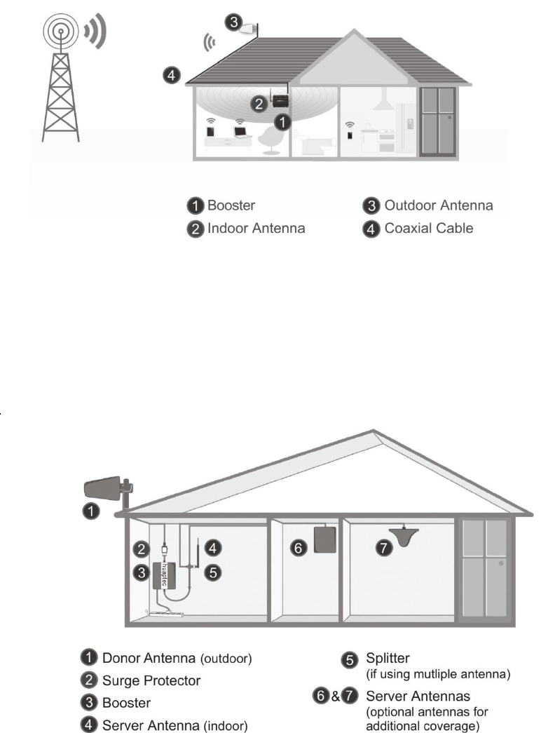
1 HOW IT WORKS
The cellular booster provides reliable two-way cellular coverage by improving signal
strength in homes, buildings, offices, and other areas where cellular reception is
weak or unreliable.
The system amplifies the signal from the nearest cellular tower and retransmits at a
higher power level within a local area.
This manual provides simple installation instructions that will have your cellular
booster kit running in record time.
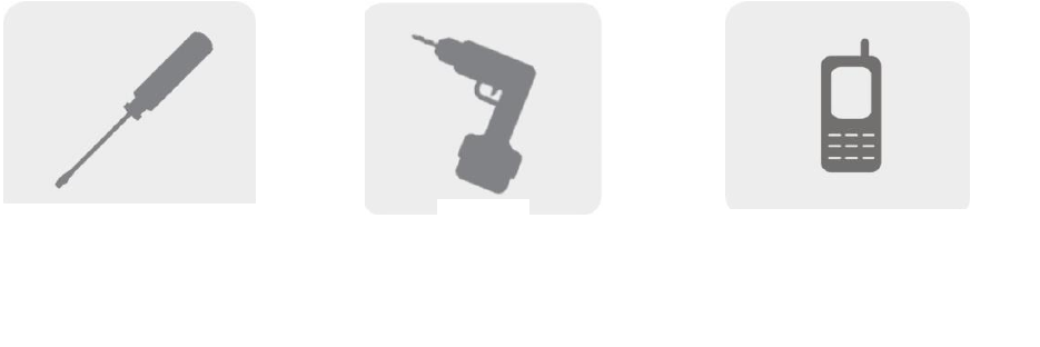
2 TOOL REQUIRED
Phillips Screwdriver
Drill
Cellular Phone (to check signal
strength)
4 / 20
3 HOW TO INSTALL YOUR NEW CELLULAR BOOSTER
3.1 Overview
This guide will help you properly install your cellular booster kit. It is important to
read through all of the installation steps before installing your equipment.
Thoroughly read through the instructions, visualize where all the equipment will
need to be installed and do a soft installation before mounting any equipment.
5 / 20
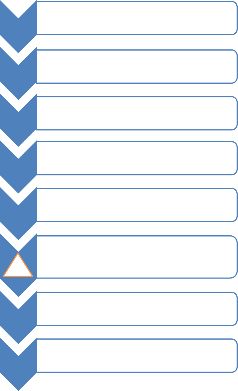
1
•BOOSTER – select location
•Install the booster in an area that is protected from the weather, properly
ventilated and is away from excessive heat and moisture.
2
•DONOR ANTENNA (OUTDOOR)- select location
•Mount the signal (outdoor) antenna in an elevated outdoor location so
that it points towards the cellular tower and away from where the inside
antenna will be located.
3
•OUTDOOR COAXIAL CABLE - select location
•The outdoor coaxial cable is used to connect the donor (outdoor) antenna
to the booster.
4
•INDOOR COAXIAL CABLE- (if used)
•The indoor coaxial cable is used to connect the server (indoor) antenna to
the booster.
5
•SERVER ANTENNA (indoor)
•The ideal location for the distribution antenna will be the area of your
property where you need to improve the signal most.
•NOTE:The signal strength will be strongest closest to the antenna.
6
•IMPORTANT: The signal antenna (outdoor)should always be separated from the
distribution antenna (indoor)by at least 20 vertical feet including the separation of
a thick barrier such as a roof or a wall. Depending on the strength of your outdoor
signal, the weaker the signal the less separation distance is required.
7
•LIGHTNING SURGE PROTECTOR- (SOLD SEPARATELY)
•The lightning surge protector connects in between the signal antenna and the
booster.
•IMPORTANT: Lightning surge protector must be grounded.
8 •COMMISSIONING THE SYSTEM
• !
!
6 / 20
3.2 Plan the layout of your system
Before you get started you will need to plan the layout of your system. This involves
checking signal strength for signals coming from the cellular tower, as well as
antenna, booster and cable placement.
3.3 Check for Signal Strength
Select a location on the roof of the building to install the signal antenna, by
monitoring your cellular phone’s signal strength (signal bars) to find the strongest
signal from your carrier’s cellular tower.
Mark that area as the installation location for the Donor (outdoor)
IMPORTANT: Confirm that you have at least 20 feet of vertical distance between
the marked antenna location and the location where you will place the Server
(indoor) antenna. To prevent the system from oscillation (feedback) you want to
ensure that there is enough separation between the distribution and signal antenna
or that they are shielded from each other to ensure the distribution antenna does
not send a signal back into the signal antenna. If you cannot achieve these
separations, either choose an alternate location for the donor (outdoor) antenna or
determine if there are natural barriers in the building construction itself that will
attenuate signals between the two antennas so that oscillation can be prevented.
3.4 Run coaxial cable
Loosely run the coaxial cable from your outdoor antenna to your booster. (After you
have tested the system you can permanently secure the coaxial cable).
As you route and pull cabling, follow these general guidelines:
Bend cables and route them smoothly, and protect the outer skin against any
damage.
Keep horizontal cables straight and fasten them with a tie every three to five
feet.
Bind and fasten vertical cables every six to eight feet.
Waterproof all outdoor connections with silicone caulking
Be careful when plugging the connector in so as not to damage the center pins
on the connectors.
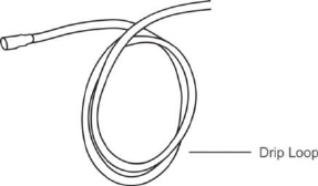
3.5 Install the Donor (Outdoor) antenna
Connect the supplied coaxial cable to the antenna. We recommend applying silicone
caulking to fully waterproof the connection.
Attach the cable in such a way that a drip loop is formed.
Once mounted, connect one end of the coaxial cable to the donor (outdoor) antenna
and the other end to the cellular booster where it is marked “Outdoor”
7 / 20
3.6 Install the Server (Indoor) antenna
Connect one end of the coaxial cable to the antenna and the other end to the cellular
booster where it is marked “Indoor”.
Select the installation location of your supplied server (outdoor) antenna based on
the following:
Omni Ceiling directional antenna
Place in the center of the area where the signal needs to be amplified.
Panel directional antenna
Place in the outer perimeter of the area the signal needs to be amplified.
Whip Omni directional antenna
Mount directly to the connector marked “Indoor” on the cellular booster.
3.7 Install your cellular booster
Install the cellular booster in a location that is properly ventilated and not exposed to
excessive heat, moisture and/or direct sunlight. The optimal area would be on a wall
located near a power outlet.
It should be mounted in an easily accessible area so it’s easy to perform general
maintenance with the coaxial cable connections, dip switch settings and power
adaptor.
Make sure all cables and antennas are securely connected before commissioning the
system.
3.8 Power up your cellular booster
Once all the Following precautions have been taken, power on the cellular booster.
1. Verify that you have left at least 20 feet of vertical separation space between the
indoor and outdoor antennas.
2. Never point the front of the yagi donor (outdoor) antenna towards the inside of
the server (outdoor)antenna.
3. Verify that the supplied coaxial cables from both the donor (outdoor) antenna
and the server (outdoor)antenna are properly connected to the cellular booster
before powering it up.
4. Carefully plug in the supplied power adaptor into the back of the cellular booster
where it is marked ‘DC 12V’ and connect the other end to a power outlet.
The LED indicator marked power should light up green.
3.9 Check the Cellular Booster Status
Your cellular booster comes equipped with electronic sensors designed to identify
cellular signal overload or oscillation which can hinder signal boosting performance.
Your cellular booster is specially designed to automatically decrease gain to
compensate for these circumstances. The device also has a feature to automatically
shut down in case of excessive oscillation. Improper equipment installation and
8 / 20
unusable signal quality can cause oscillation, this is why it is important to fully
understand the LCD indications on your booster, as they will help you identify and
solve any potential issues.
The LCD indicates the status of the booster system.
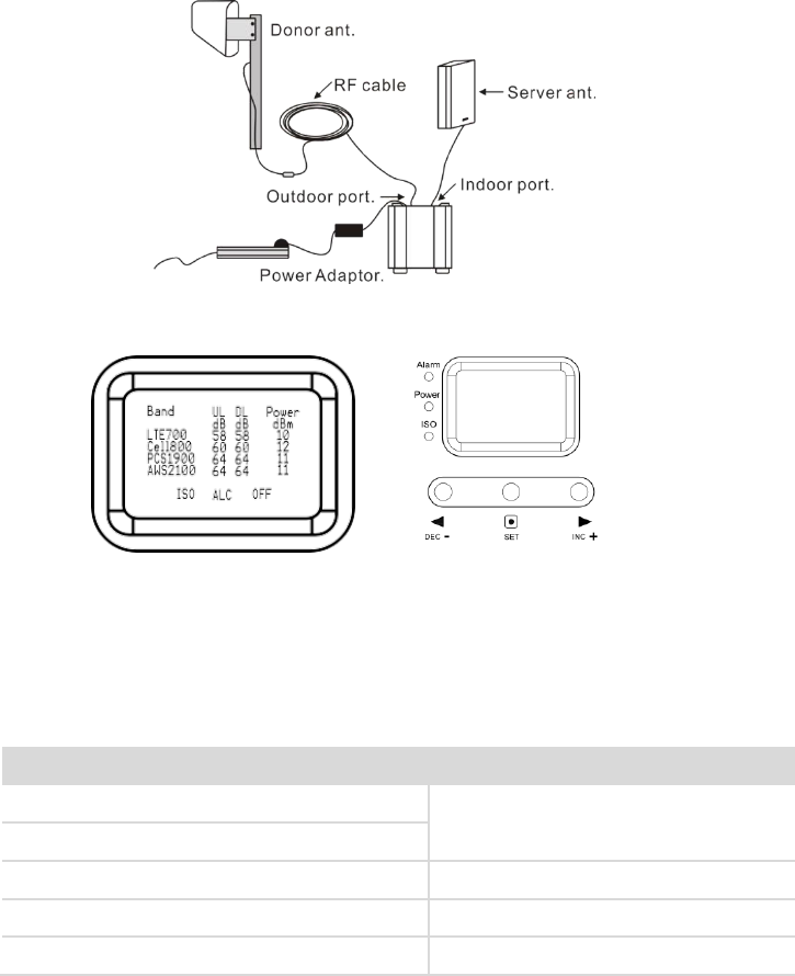
4 UNDERSTAND THE PORTS, LCD and LED STATUS,MGC
4.1 Repeater ports
1) Outdoor port: connected with the donor antenna by cable.
2) Indoor port: connected with server antenna directly or by cable.
3) DC IN: connected with power supply.
4.2 LCD Features
After the booster is powered on, uplink (UL) and downlink(DL) gain and DL output
power are displayed. “Band”– Shows the working frequency. Below is a list of the
frequencies displayed corresponding to the Band display shown on the screen.
“UL (dB)”“DL (dB)”– Gain Indication.
The displayed value shows real-time uplink and downlink gain. These values
will change slightly as the ALC or ISO makes changes to the gain to optimize
Frequency
Band display
700MHz Lower A/B/C blocks
LTE700
700MHz Upper C block
CDMA800&GSM850&UMTS850
Cell800
PCS1900
PCS1900
AWS2100
AWS2100
9 / 20
coverage.
“Power dBm”– Power Indication.
The displayed value shows real-time downlink power that the amplifier is delivering
to the indoor antenna port. When the amplifier DL output power is lower than
-10dBm, the value will display ”---”.
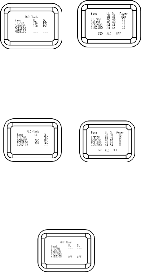
“ISO” – Isolation Alarm Indication.
When the system does not have enough isolation between the outdoor and indoor
antennas, the “ISO” indicators will be flashing showing that the ISO is lowering the
gain in some bands to keep the system from oscillating. Press the ”SET” key and the
LCD screen will display ”ISO” showing the current band or bands affected.
“ALC” Flashing.
When the amplifier is receiving too much DL power from the tower and the DL
amplifier output is close to saturating, the “ALC” indicators will flash showing that
the ALC has lowered the gain to prevent this overload condition. Press the ”SET”
button and the screen will show the band or bands affected.
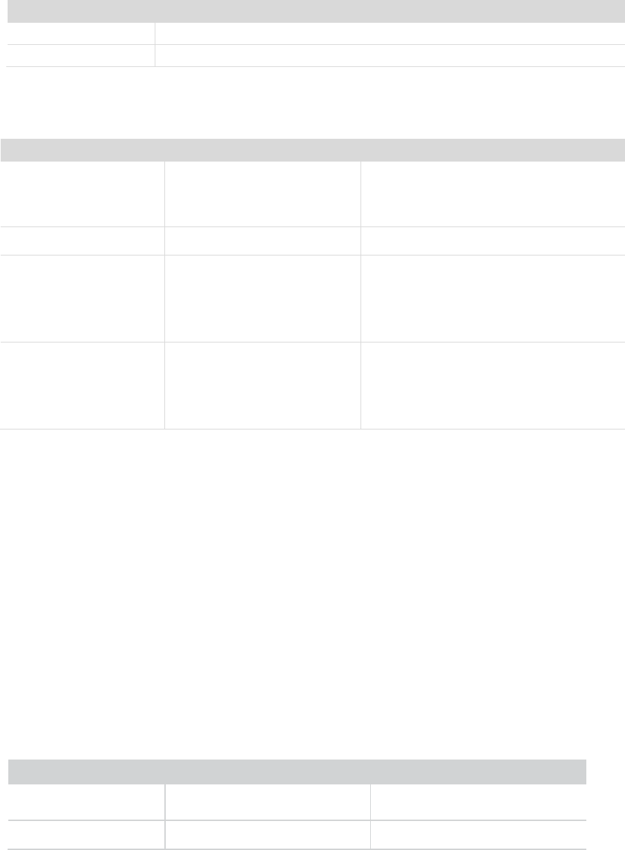
”OFF”- Booster shut-off alarm indication.
In some rare situations the ALC or ISO will not be able to compensate for an
oscillation condition or a downlink overload. When this happens the amplifier
will shut off in the affected band and the LCD “OFF” indicator will flash. Pressing
the “SET” button will display which band or bands are affected.
10 / 20
4.3 LED Status
1. Status and definition of Power indicator:
Status
Definition
Green
Normal
Off
DC power problem
2. Status and Definition of Alarm indicator; Alarm LED only works for downlink
signals
Measures: The below actions are recommended to eliminate "Quick Flashing Green"
and "Quick Flashing Red".
1. Adjust the antennas’ directions or locations to lower downlink received signal
level.
2. Slowly reduce the downlink gain using the Manual Gain Controls.
3. If the above methods don’t work, reduce the booster’s gain with an external
attenuator in line with the outdoor antenna or replace with lower gain antenna.
Target: The overload issues are fixed when the Alarm LED is "Green" or "Slow
Flashing Green". Please note that a "Green" LED indication may result in smaller
coverage area. This can be improved by adjusting the outdoor antenna to receive a
stronger signal.
3. Status and Definition of ISO indicator; ISO LED only works for downlink signals
Status
Meaning
Solve methods
Green
Output power is not maximum.
Check coverage, leave as is if it's good; if
coverage is not good, increase downlink
signal Level.
Slow Flashing Green
Full output power
Working properly.
Quick Flashing Green
Output power is too high.
Not working properly.
Check coverage, leave as is if it’s good.
Actions must be taken if the coverage is not
good.
Quick Flashing Red
The booster automatically shuts
off for protection from
excessive downlink signal from
tower.
Not working properly.
Take the actions below.
Status
Meaning
Solution methods
Green
No loop back or no self-oscillation
NO action is needed
Slow Flashing Green
Slight loop back or self-oscillation
NO action is needed

11 / 20
Measures: One of the actions below are recommended to eliminate ISO problems,
please note that these actions are the same for "Quick flashing green" , "Quick
Flashing red" and “OFF”.
1. Adjust the antennas’ pointing directions or locations or increase the distance
between them.
2. Increase the vertical or horizontal distance between the outdoor antenna and
indoor antenna.
3. Use barriers like walls to increase the isolation.
4. Change the indoor antenna type to an antenna with a more directional antenna
pattern. Orient the indoor antenna and outdoor antenna so they point in
opposite directions.
5. Reduce the booster’s downlink gain using the manual gain controls. Keep the
uplink gain value and downlink gain value the same then restart the booster.
Note: Uplink gain must be equal to or not less than 5dB below the downlink gain,
to avoid interference with the local carrier’s cell site network.
Target: The ISO issues are solved when the ISO LED is "Green" or "Slow Flashing
Green".
4.4 Manual Gain Control Operation
There are 4 operation modes relative to the control buttons: a long press for more
than 3 seconds on the “SET” button, short press on the “SET” button, short press on
“DEC-” button and short press on “INC+” button.
When the LCD is in the fixed display mode, press the “SET” key for 3 seconds and it
will start up in the Gain Setting Mode.
Press the “SET” key shortly, and the LCD will switch to the next value (uplink
or downlink gain for a different band).
Press the “INC+” (or “DEC-”) key, and the value of the current gain item will
change to a higher (or lower) one.
Press the “SET” key for 3 seconds, and the LCD will return to the fixed
display mode. (For more details refer to Manual Gain Control (MGC) below.
Quick Flashing Green
Deep loop back or self-oscillation
Not working properly.
Check coverage. Leave it as is if it’s
good. Actions must be taken if
coverage is not good.
Quick Flashing Red
Severe loop back or self- oscillation
Not working properly, actions must be
taken.
OFF
The booster automatically shuts off
for protection due to very severe
self- oscillation.
12 / 20
When the LCD is in the alarm display mode, press the “SET” key and the LCD screen
will display the alarm indication showing the affected band. Pressing the “INC+” (or
“ DEC-“) key and the LCD will switch to help tips. If none of keys are depressed within
30 seconds, the display will return to the fixed display mode.
If none of the control keys are depressed within 5 minutes, the LCD screen will turn
off. Pressing any key will return the display to the fixed mode.
4.5 Manual Gain Control (MGC)
Since the booster has a very good self-adaptive smart automatic level control (ALC)
and isolation gain processing (ISO) , most of the time manual adjustments are not
required to achieve good coverage. However, in some cases where the ALC or ISO is
working at a very high rate to adjust the gain and the Alarm or ISO LED is flashing
more than once a second a manual adjustment might be desired.
When the LCD is in the fixed display mode, press the “SET” key for more than 3
seconds. It will go into the “Gain Setting Mode” and make one of the gain values start
to blink.
Press “SET” key shortly, and the LCD will switch to the next gain value and it
will start to blink. (uplink or downlink gain for a different band).
Press “INC+” key once shortly and the gain will increase by 1dB, Press
“DEC-”once shortly and the gain value will be reduced by 1dB.
Press the “SET” key for 3 seconds, and the LCD will return to the fixed
display mode.
Note: When adjusting the gain manually, please ensure that the uplink gain
is equal to or not 5 dB less than the downlink gain setting. This avoids
interference with the local cell site tower network.
13 / 20
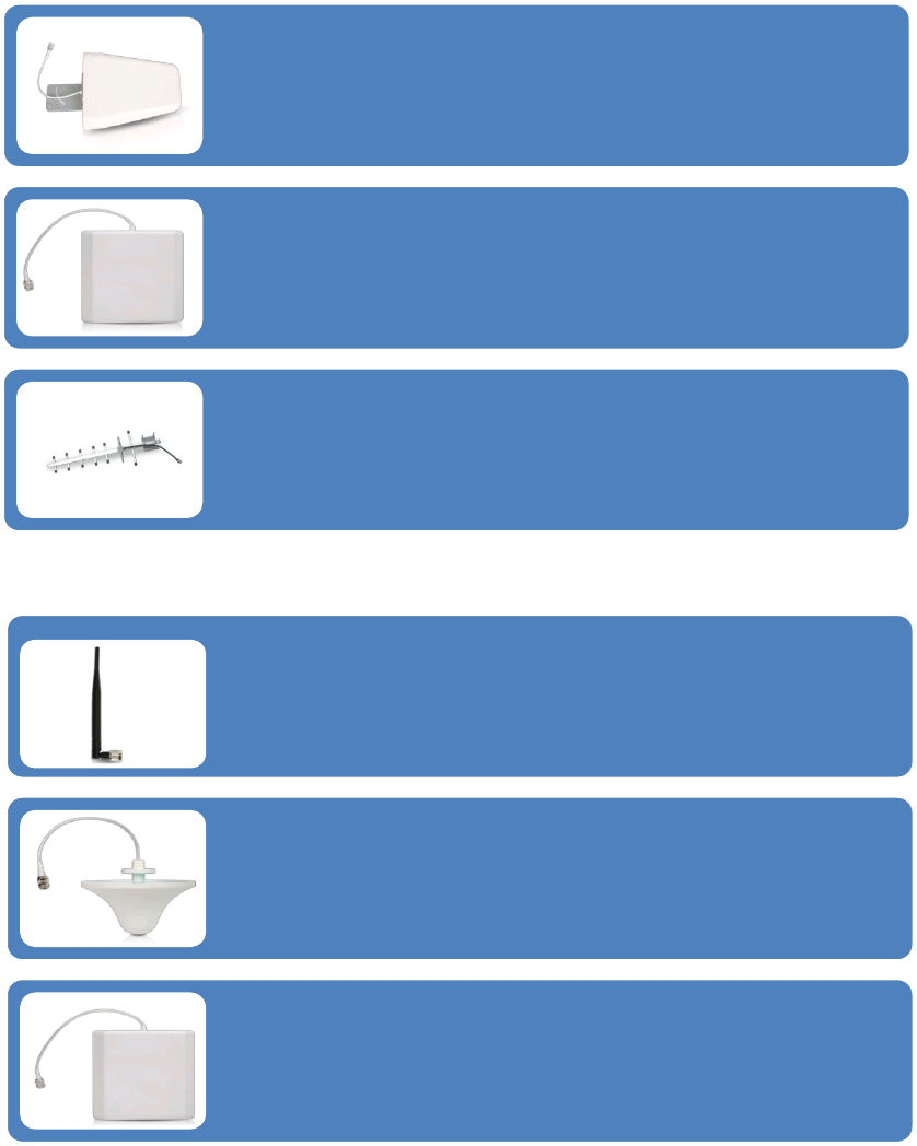
5 UNDERSTAND THE ANTENNA
5.1 Donor (Outdoor) antenna
5.2 Server (Indoor) antenna
5.3 Authorized Kitting Options
Outdoor Default Antenna & Cable Kit Options
1. Kit 9-5050
Outdoor Yagi 9dbi Antenna & 50’ 5D Coaxial Cable
Indoor Default Antenna & Cable Kit Options
1. Kit 72-5050-50
2 Panel 7dbi Antenna with50' 5D N male & a 50 Ohm 2-Way Splitter
The Yagi Lpda Antenna
The yagi is a very precise directional antenna with a powerful reach. This
antenna should be installed in an elevated position and must be pointed
towards your carrier’s cellular tower.
NOTE:This antenna is not meant to capture signal from multiple carriers.
The Panel Antenna
The panel is a directional antenna with a 120 degree reach and is designed to
capture the signal from multiple carrier towers. This antenna should be
installed in an elevated position and must be pointed towards your carrier’s
cellular towers.
Yagi Antenna
The yagi is a very precise directional antenna with a powerful reach. This
antenna should be installed in an elevated position and must be pointed
towards your carrier’s cellular tower.
NOTE: This antenna can only support single band signal booster.
The Whip Antenna
The whip antenna is an omni-directional antenna with a 360 degree reach. It
is designed to distribute the signal from the center of the affected area.
Typically it is connected directly to the booster.
The Omni Antenna
The omni antenna is an omni-directional antenna with a 360 degree reach. It
is designed to distribute the signal from the center of the affected area.
Typically it is installed in a false or dropped ceiling.
The Panel Antenna
The panel is a directional antenna with a 120 degree reach and is designed to
distribute the signal from a perimeter wall or ceiling.
14 / 20
Outdoor Antenna & Cable Kit Options
2.Kit 11-100400
Yagi 11dbi Antennac& 100' 400 Coaxial Cable
3. Kit 11-7550
Yagi 11dbi Antenna & 75' 5D Coaxial Cable
4. Kit 11-100500
Yagi 11dbi Antenna & 100' 5D Coaxial Cable
5. Kit 10-3050
Panel 10dbi Antenna & 30' 5D Coaxial Cable
6. Kit 10-50400
Panel 10dbi Antenna & 50' 400 Coaxial Cable
7. Kit 10-5050
Panel 10dbi Antenna & 50' 5D Coaxial Cable
8. Kit 10-75400
Panel 10dbi Antenna & 75' 400 Coaxial Cable
9. Kit 10-100400
Panel 10dbi Antenna & 100' 400 Coaxial Cable
10. Kit 10-7550
Panel 10dbi Antenna & 75' 5D Coaxial Cable
11. Kit 10-10050
Panel 10dbi Antenna & 100' 5D Coaxial Cable
12. Kit 9-50400
Yagi 9dbi Antenna & 50' 400 Coaxial Cable
13. Kit 9-75400
Yagi 9dbi Antenna & 75' 400 Coaxial Cable
14. Kit 9-100400
Yagi 9dbi Antenna & 100' 400 Coaxial Cable
15. Kit 9-7550
Yagi 9dbi Antenna & 75' 5D Coaxial Cable
16. Kit 9-10050
Yagi 9dbi Antenna & 100' 5D Coaxial Cable
17. Kit 7-3050
Panel 7dbi Antenna & 30' 5D Coaxial Cable
18. Kit 7-50400
Panel 7dbi Antenna & 50' 400 Coaxial Cable
19. Kit 7-5050
Panel 7dbi Antenna & 50' 5D Coaxial Cable
20. Kit 7-75400
Panel 7dbi Antenna & 75' 400 Coaxial Cable
21. Kit 7-100400
Panel 7dbi Antenna & 100' 400 Coaxial Cable
22. Kit 7-7550
Panel 7dbi Antenna & 75' 5D Coaxial Cable
15 / 20
23. Kit 7-10050
Panel 7dbi Antenna & 100' 5D Coaxial Cable
24. Kit 5-30400
Omni 5dbi Antenna & 30' 400 Coaxial Cable
25. Kit 5-3050
Omni 5dbi Antenna & 30' 5D Coaxial Cable
26. Kit 5-50400
Omni 5dbi Antenna & 50' 400 Coaxial Cable
27. Kit 5-5050
Omni 5dbi Antenna & 50' 5D Coaxial Cable
28. Kit 5-75400
Omni 5dbi Antenna & 75' 400 Coaxial Cable
29. Kit 5-10400
Omni 5dbi Antenna & 100' 400 Coaxial Cable
30. Kit 5-7550
Omni 5dbi Antenna & 75' 5D Coaxial Cable
31. Kit 5-10050
Omni 5dbi Antenna & 100' 5D Coaxial Cable
Indoor Antenna & Cable Kit Options
2. Kit 52-5050-50
2 Whip 5dbi Antenna &50' 5D Coaxial Cable & a 50 Ohm 2-Way Splitter
3. Kit 102-5050-50
2 Panel 10dbi Antenna with50' 5D N male & a 50 Ohm 2-Way Splitter
4. Kit 103-7550-50
3 Panel 10dbi Antenna & 75' 5D Coaxial Cable & a 50Ohm 3-Way Splitter
5. kit 104-7550-50
4 Panel 10dbi Antenna & 75' 5D Coaxial Cable & three 50 Ohm 2-Way Splitter
6. Kit 73-7550-50
3 Panel 7dbi Antenna & 75' 5D Coaxial Cable & a 50Ohm 3-Way Splitter
7. kit 74-7550-50
4 Panel 7dbi Antenna & 75' 5D Coaxial Cable & three 50 Ohm 2-Way Splitter
8. Kit 3-1550
Omni 3dBi Antenna with 15' 5D Coaxial Cable
9. Kit 3-30400
Omni 3dBi Antenna with 30' 400 Coaxial Cable
10. Kit 3-5050
Omni 3dBi Antenna & 50' 5D Coaxial Cable
11. Kit 3-7550
Omni 3dBi Antenna & 75' 5D Coaxial Cable
12. Kit 3-10050
Omni 3dBi Antenna & 100' 5D Coaxial Cable
13. Kit 3-30400
Omni 3dBi Antenna with 30' 400 Coaxial Cable

16 / 20
14. Kit 3-50400
Omni 3dBi Antenna & 50' 400 Coaxial Cable
15. Kit 3-75400
Omni 3dBi Antenna & 75' 400 Coaxial Cable
16. Kit 3-100400
Omni 3dBi Antenna & 100' 400 Coaxial Cable
17. Kit 32-50400-50
2 Omni 3dBi Antenna & 50' 400 Coaxial Cable & a 50 Ohm 2-Way Splitter
18. Kit 33-50400-50
3 Omni 3dBi Antenna & 50' 400 Coaxial Cable & a 50 Ohm 3-Way Splitter
19. Kit 34-50400-50
4 Omni 3dBi Antenna &50' 400 Coaxial Cable & three 50 Ohm 2-Way Splitter
6 TROUBLESHOOTING
The LCD screen displays the status of the booster on each frequency. When there are
not “ALC” and “ISO” indication, the device is operating normally meaning that it is
not experiencing any oscillation (feedback) and it is boosting the signal at maximum
gain. When the “ALC” and “ISO” is flashing, it means that particular frequency is
experiencing some oscillation (feedback) or too strong signal from tower.
If the oscillation is excessive the booster will shut down for that particular frequency.
The booster will still work for the other frequency on a multi-band booster.
Oscillation is caused when the indoor (distribution) antenna sends a signal back into
the outdoor (signal) antenna. Similar to a PA system, when the microphone gets too
close to the speaker it causes feedback. This will occur if your antennas are too close
together, or the indoor antenna is pointed at the outdoor antenna. Make sure you
have adequate separation and some type of shielding between the antennas (Usually
your roof or a cement wall is good enough).
IMPORTANT NOTES
The 2 most important things to look for when setting up your system is:
By capturing the best input signal you will be able to enjoy the maximum coverage
and best quality signal inside where your Indoor antennas are located. The better the
input signal, the better the output signal. In order to find the best input signal, you
want to place your outdoor antenna as high as possible with the least amount of
obstruction between the antenna and the cellular base tower. A clear line of site is
ideal.
Isolating the signal from the antennas is done by ensuring that the antennas are not
pointing to each other and by having enough distance or barrier shielding in between
A good input signal (the best you can find)
Isolating the outdoor (donor) antenna from the indoor
(server) antennas so they do not feedback into each other.

17 / 20
them. The signals travel like rays of sunlight, a directional antenna will send the signal
in the direction that it is pointing. An omni directional antenna will send the signal in
every direction around it. So depending on your equipment it’s important to be sure
that your Indoor antenna is not sending the signal back into the outdoor antenna.
THINGS TO CHECK WHEN EXPERIENCING WEAK CELLULAR SIGNAL
1. Ensure the outdoor antenna is pointing in the correct direction and is capturing
adequate signal for the booster.
2. Check all connections on the cable, antennas, and booster.
3. Check cable for bends and or cuts.
4. All LED lights on the booster should be green or there are not “ALC” and “ISO”
indication on LCD.
5. Outdoor antenna and the indoor antennas have adequate separation and are
not causing feedback.
7 FREQUENTLY ASKED QUESTIONS
WHY ARE THE LED LIGHTS TURNING FLASHING GREEN, FLASHING
RED OR SHUTTING OFF?
There are certain cases where your system could be experiencing
oscillation. This can be attributed to either the quality of your input signal
or having your outdoor antenna and indoor antenna too close together. Please
review the following guidelines to help resolve this issue:
1. Adjust the direction of the outdoor antenna. If the system is receiving a very high
input signal, you can point your outdoor antenna away from the cellular tower to
reduce the strength of the input signal and therefore, reduce the oscillation.
Alternatively if your system is receiving a very poor quality signal (weak and
unusable signal), you can point your outdoor antenna more directly towards the
cellular tower to increase the strength of the input signal. Sometimes this may
require completely repositioning the antenna to a location where you can
achieve a line of site to the tower.
2. Increase the separation between the outdoor antenna and the indoor antenna.
This can be achieved by increasing the distance between the two antennas or by
placing barriers between them, such as moving the indoor antenna to an
adjacent room where there would be an additional wall separating them from
the outdoor antenna.
3. Manual Gain Control. Adjust the gain with the manual gain control function
using the dip switches on the side of the booster.
8 FCC RF Exposure Statement
This equipment complies with FCC radiation exposure limits set forth for an
uncontrolled environment. End users must follow the specific operating instruction
for satisfying RF exposure compliance. This transmitter must not be co-located or
operating in conjunction with any other antenna or transmitter.
18 / 20
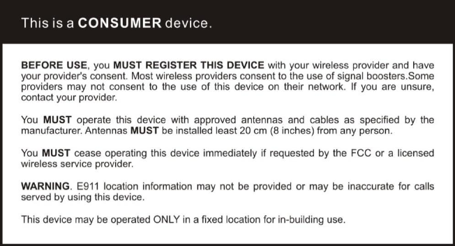
9 Warning and Statement
Note:This equipment has been tested and found to comply with the limits for a Class
B digital device, pursuant to Part 15 of the FCC Rules. These limits are designed to
provide reasonable protection against harmful interference in a residential
installation. This equipment generates, uses and can radiate radio frequency
energy and, if not installed and used in accordance with the instructions, may cause
harmful interference to radio communications. However, there is no guarantee that
interference will not occur in a particular installation. If this equipment does cause
harmful interference to radio or television reception, which can be determined by
turning the equipment off and on, the user is encouraged to try to correct the
interference by one or more of the following measures:
Reorient or relocate the receiving antenna.
Increase the separation between the equipment and receiver.
Connect the equipment into an outlet on a circuit different from that to which
the receiver is connected.
Consult the dealer or an experienced radio/TV technician for help.
Changes or modifications not expressly approved by Huaptec could void the user's
authority to operate the equipment.
Note: For a complete list of antennas and cables approved for use with these
boosters see 5.3 Authorized Kitting Options pages 13&14&15&16.
FCC 27.50(d)(4)Statement: Fixed, mobile, and portable (hand-held) stations
operating in the 1710-1755 MHz band are limited to 1 watt EIRP. Fixed stations
operating in the 1710-1755 MHz band are limited to a maximum antenna height of
10 meters above ground.
19 / 20
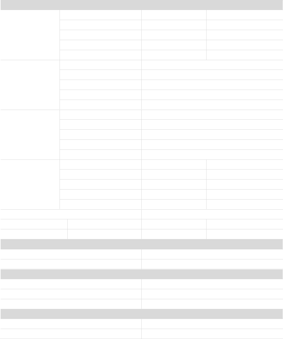
10 Specification
F20G-5S-LCD
RF Parameter
Uplink
Downlink
Frequency
Range
700MHz Lower(A+B+C)
698~716MHz
704~746MHz
700MHz Upper C
776~787MHz
746~757MHz
Cell800
824~849MHz
869~894MHz
PCS1900
1850~1915MHz
1930~1995MHz
AWS2100
1710~1755MHz
2110~2155MHz
Band width
700MHz Lower(A+B+C)
18MHz
700MHz Upper C
11MHz
Cell800
25MHz
PCS1900
65MHz
AWS2100
45MHz
Max .Gain
700MHz Lower(A+B+C)
56~63.5dB
700MHz Upper C
56~64.4dB
Cell800
59~65dB
PCS1900
62~72dB
AWS2100
62~71.3dB
Max .Output
Power
LTE (A+B)
17~24dBm
9~12dBm
LTE C
17~24dBm
9~12dBm
CDMA
17~24dBm
9~12dBm
PCS
17~24dBm
9~12dBm
AWS
17~24dBm
9~12dBm
MGC ( Step Attenuation )
31dB/1dBstep
Inter-modulation
9KHz~12.75GHz
≤-19dBm
≤-19dBm
Spurious Emission
9KHz~12.75GHz
≤-13dBm
≤-13dBm
Electrical Parameter
Standard
Power Supply DC12V/3A
Input & Output Impedance 50 ohm
Input AC90~264V.45~60Hz, Output
DC12V/3A
Input & Output Impedance 50 ohm
Input & Output Impedance
Input & Output Impedance 50 ohm
50 ohm
Input & Output Impedance 50 ohm
Mechanical Specifications
Standard
I /O Port
N-Female
Dimensions
218*165*50mm
Weight
≤ 2.5Kg
Environment Parameter
Standard
Operating Temperature
-25ºC~+55ºC
Environment Conditions
IP40
20 / 20
FURTHER INFORMATION ON SIGNAL BOOSTER END-USE REGISTRATION
The following is currently active contact of US wireless provider for booster register.
https://www.uscellular.com/uscellular/support/fcc-booster-registration.jsp
https://www.sprint.com/legal/fcc_boosters.html
https://www.verizonwireless.com/solutions-and-services/accessories/register-signal-
booster/
https://support.t-mobile.com/docs/DOC-9827
https://securec45.securewebsession.com/attsignalbooster.com/
SHENZHEN HUAPTEC CO., LTD
5th FL, E BLDG, Sogood Science Park, Hangkong Road, Xixiang, Bao'an,
Shenzhen, China 518102
Phone/Fax: 086-0755-29921615
Website: www.huaptec.com
Huaptec US Inc.
6210 N Belt Line Rd., Ste. 110, Irving, TX 75063
Phone/Fax: (972) 870-5666
E-mail: info@huaptecus.com
Website: www.huaptecus.com