HUBER SUHNER SL60100 Point to Point Radio User Manual Manual SL60 100 5764 E O
HUBER+SUHNER AG Point to Point Radio Manual SL60 100 5764 E O
UserManual.wiki
>
HUBER SUHNER
>
SL60100 User Manual
Manual
Navigation menu
Upload a User Manual
Namespaces
Wiki Guide
HTML
PDF
Info
Views
User Manual
Discussion / Help
Navigation
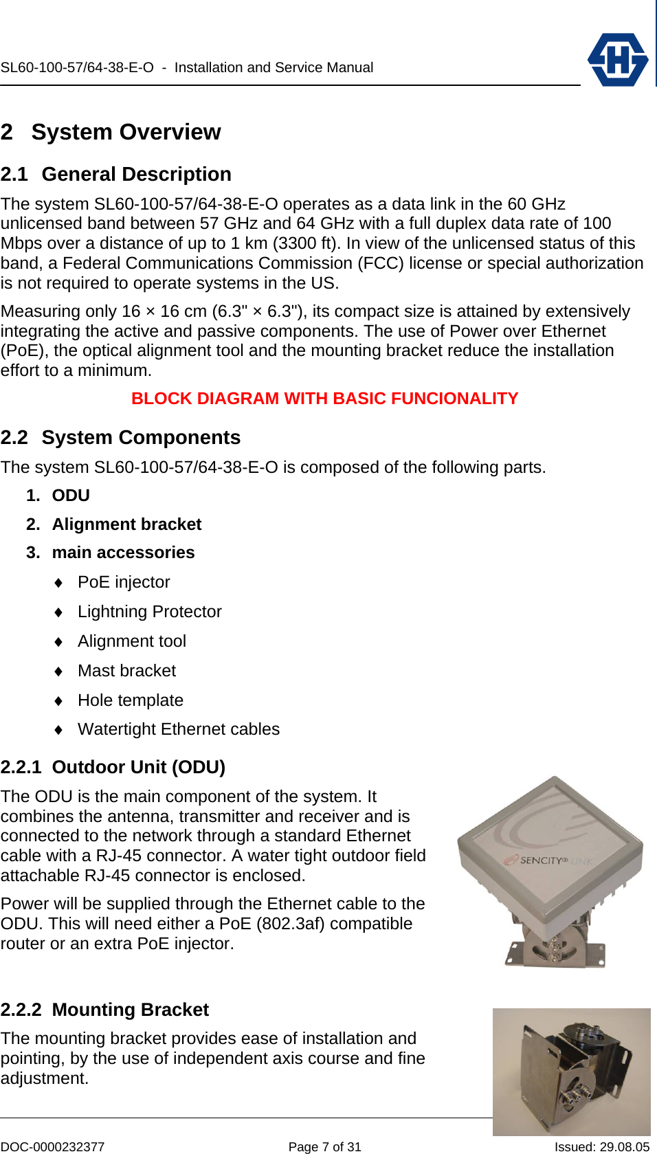
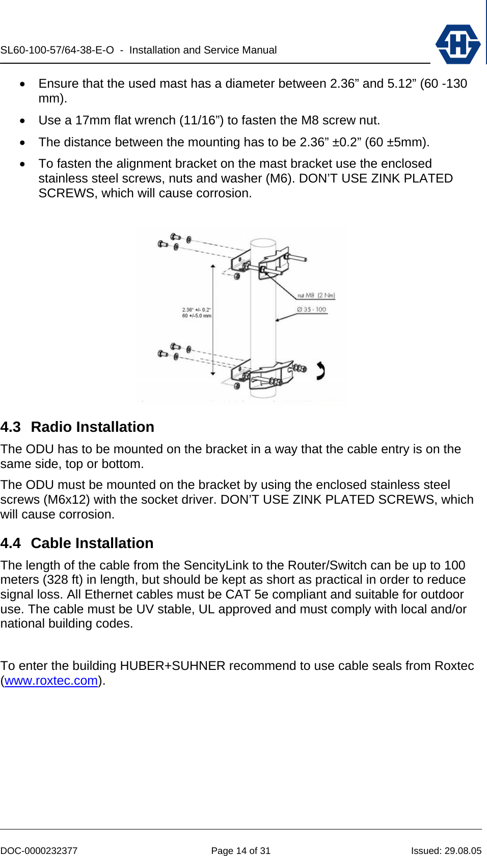
![SL60-100-57/64-38-E-O - Installation and Service Manual DOC-0000232377 Page 9 of 31 Issued: 29.08.05 3 Site Planning It is necessary that the installer performs an inspection of the site and plans the installation prior the physical installation of SL60-100-57/64-38-E-O. This inspection and planning tasks include: ♦ Evaluate the appropriate location for the installation of the links (see section 3.1). ♦ Identifying an appropriate mounting structure (wall or mast) for each link. ♦ Planning the cable routing from your network component to the link. ♦ Setting up the proper network configuration for the links (see 4.9) 3.1 Line of Sight Radio transmission requires a clear path between antennas known as radio line of sight (LOS). To have a clear line of sight there must be no obstructions between the two locations. The clearance necessary to operate can be established visually. The following table helps to decide if an obstacle interferes with the radio line of sight requirements. link distance[m]link distance[ft]Boundary diameter[m]Boundary diameter[ft]100 328 0.4 1.2400 1312 0.7 2.3600 1968 0.9 2.8800 2625 1.0 3.31000 3281 1.1 3.7 3.2 Radio Location When selecting the best link location the following factors should be considered: • Accessibility (roof, etc.) • Type of mounting (wall / pole) • Grounding connection point (see 3.6) • Cable runs (max. 100m) • Line of sight (see 3.1) 3.3 Link Distance / Link Availability The link distance or separation between the link ends is directly related to the tolerable BER (Bit error rate) and path availability. The influence of BER on Ethernet transmission depends on the size of the transmitted packets and their bit sequence. A rough rule of the thumb says good Ethernet connections can be achieved with 10-6 BER. The affordable link availability is influenced by following environmental conditions: • Rain the lesser the better • Temperature the higher the better](https://usermanual.wiki/HUBER-SUHNER/SL60100/User-Guide-619098-Page-9.png)
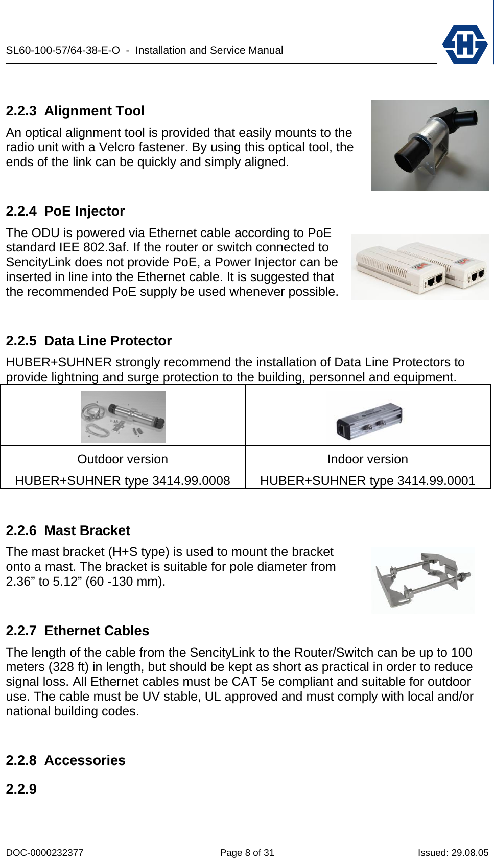
![SL60-100-57/64-38-E-O - Installation and Service Manual DOC-0000232377 Page 15 of 31 Issued: 29.08.05 4.5 Antenna Alignment An outstanding property of SencityLink is the easy and fast alignment procedure. The radios can be aligned optically by using the alignment tool. No electrical alignment is required. The table below shows the precision needed for a proper link operation. link distance[m]link distance[ft]spot diameter[m]spot diameter[ft]100 328 0.9 2.9400 1312 3.5 11.5600 1968 5.2 17.2800 2625 7.0 22.91000 3281 8.7 28.61200 3937 10.5 34.4 4.5.1 Alignment Procedure The following procedure is used to achieve a fast and precise alignment (for all operations the enclosed 5mm socket driver can be used). (1) Mount the alignment tool on the most reachable edge of the ODU. (2) place the course screw of the horizontal axis in the middle position (needle) (3) make a rough alignment on the horizontal axis and fasten the fine screw (4) repeat step (1) and (2) for the vertical axis (5) Turn the course screw of the horizontal axis by viewing trough the telescope and do the fine alignment. (6) repeat (5) for the vertical axis (7) If necessary repeat the fine alignment procedure (5) for both axis till the opposite link is pointed.](https://usermanual.wiki/HUBER-SUHNER/SL60100/User-Guide-619098-Page-15.png)