HUBER SUHNER SL60100 Point to Point Radio User Manual Manual SL60 100 5764 E O
HUBER+SUHNER AG Point to Point Radio Manual SL60 100 5764 E O
Manual
SL60-100-57/64-38-E-O - Installation and Service Manual
DOC-0000232377 Page 1 of 31 Issued: 29.08.05
Installation and Service Manual
SL60-100-57/64-38-E-O
Revision A.01
Issued: September 2005

SL60-100-57/64-38-E-O - Installation and Service Manual
DOC-0000232377 Page 2 of 31 Issued: 29.08.05
This device complies with part 15 of the FCC rules. Operation is subject to the
following two conditions.
1) This device may not cause harmful interference, and
2) This device must accept any interference received, including interference
that may cause undesired operation.
If this product is suspected of causing harmful interference with other equipment,
discontinue operation immediately and contact HUBER+SUHNER.
In order to meet FCC RF Exposure requirements, this device must be installed in
such a way that a distance of 2 m is always maintained between the device
antenna and nearby persons.
Modifications or substitutions made on the unit or parts of it without the written
approval of HUBER+SUHNER could void the user’s authority to operate the
equipment.
FCCID TTDSL60100

SL60-100-57/64-38-E-O - Installation and Service Manual
DOC-0000232377 Page 3 of 31 Issued: 29.08.05
1 Introduction.......................................................................................................... 5
1.1 Purpose........................................................................................................ 5
1.2 Revision ....................................................................................................... 5
1.3 Prior Knowledge........................................................................................... 5
1.4 Safety........................................................................................................... 5
1.5 Warranty....................................................................................................... 6
1.6 Copyright / Disclaimer .................................................................................. 6
2 System Overview ................................................................................................ 7
2.1 General Description...................................................................................... 7
2.2 System Components.................................................................................... 7
2.2.1 Outdoor Unit (ODU) .............................................................................. 7
2.2.2 Mounting Bracket .................................................................................. 7
2.2.3 Alignment Tool ...................................................................................... 8
2.2.4 PoE Injector........................................................................................... 8
2.2.5 Data Line Protector ............................................................................... 8
2.2.6 Mast Bracket ......................................................................................... 8
2.2.7 Ethernet Cables .................................................................................... 8
2.2.8 Accessories........................................................................................... 8
2.2.9 .................................................................................................................... 8
3 Site Planning ....................................................................................................... 9
3.1 Line of Sight ................................................................................................. 9
3.2 Radio Location ............................................................................................. 9
3.3 Link Distance / Link Availability .................................................................... 9
3.4 Radio Mounting Options............................................................................. 10
3.5 Cabling....................................................................................................... 11
3.6 Grounding / Lightning Protection................................................................ 11
3.7 Network Diagram........................................................................................ 12
3.8 Co-located Applications.............................................................................. 12
4 Installation ......................................................................................................... 13
4.1 Unpacking .................................................................................................. 13
4.2 Mount Installation ....................................................................................... 13
4.3 Radio Installation........................................................................................ 14
4.4 Cable Installation........................................................................................ 14
4.5 Antenna Alignment..................................................................................... 15

SL60-100-57/64-38-E-O - Installation and Service Manual
DOC-0000232377 Page 4 of 31 Issued: 29.08.05
4.5.1 Alignment Procedure........................................................................... 15
4.6 Grounding .................................................................................................. 16
4.7 Lightning Protector ..................................................................................... 16
4.8 Power Injector ............................................................................................ 16
4.9 Network Configuration / Unit Control Functions.......................................... 17
4.10 Optional items ............................................................................................ 24
5 Appendix ........................................................................................................... 27
5.1 Specification............................................................................................... 27
5.1.1 Receiver.............................................................................................. 27
5.1.2 Transmitter.......................................................................................... 27
5.1.3 Antenna............................................................................................... 27
5.1.4 Mechanical.......................................................................................... 27
5.1.5 Environmental ..................................................................................... 27
5.1.6 Network Management ......................................................................... 27
5.2 Troubleshooting.......................................................................................... 27
5.2.1 Power and Network Connection.......................................................... 27
5.2.2 Network Configuration......................................................................... 27
5.2.3 Duplex Mismatch................................................................................. 28
5.2.4 Miss-alignment.................................................................................... 28
5.3 Contacts..................................................................................................... 28
5.3.1 Technical Assistance .......................................................................... 28
5.3.2 Service Center / RMA ......................................................................... 28
6 Glossary ............................................................................................................ 29

SL60-100-57/64-38-E-O - Installation and Service Manual
DOC-0000232377 Page 5 of 31 Issued: 29.08.05
1 Introduction
1.1 Purpose
This manual is intended for installation and service personnel who are involved in the
planning, installation, operation, and maintenance of the SL60-100-57/64-38-E-O
equipment.
Please read the complete manual prior the unpacking and installation of this
equipment.
The information in this manual covers the proper installation and setup of a SL60-
100-57/64-38-E-0 ( SL 60 ) Ethernet radio link. It should be read and understood by
the installation personnel prior to the deployment of the SL 60 equipment.
While the SL 60 is designed for ease of installation and setup, optimum performance
can be achieved by following the procedures outlined in this manual.
1.2 Revision
HUBER+SUHNER reserves the right to revise this documentation and to make
changes in content from time to time without obligation on the part of
HUBER+SUHNER to provide notification of such revision or change.
1.3 Prior Knowledge
This manual assumes that the person installing this equipment has at least basic
experience with and understanding of, as well as some familiarity with the
configuration and operation of networking equipment. The persons installing this
equipment should fully understand the information covered within this manual prior to
installing this equipment.
1.4 Safety
The following general safety precautions must be observed during all phases of
operation and service of the products covered in this manual. Failure to comply with
these precautions or with specific warnings elsewhere in this manual willfully violates
standards of design, manufacture, and intended use of the product.
♦ The SL60-100-57/64-38-E-O meets all FCC electrometric radiation safety
requirements for radio equipment; however, it is best to avoid long-term
exposure to the front of the radio while operating this equipment.
♦ The outdoor equipment must be properly grounded to provide some
protection against voltage surges and built-up static charges.
♦ All electrical and mechanical installations must comply with local and/or
national electrical and building codes.
♦ Do not modify the equipment or substitute parts of the equipment.
WARNING and DANGER statements have been strategically placed in the text to
alert personnel of possible hazards. These statements must be closely observed.

SL60-100-57/64-38-E-O - Installation and Service Manual
DOC-0000232377 Page 6 of 31 Issued: 29.08.05
1.5 Warranty
HUBER+SUHNER warrants to the original end user (purchaser) that this product is
free from any defects in materials or workmanship for a period of up to one year from
the date of shipment to the end user.
During the warranty period, and upon proof of purchase, should the product have
indications of failure due to faulty workmanship and/or materials, HUBER+SUHNER
will, at its discretion, repair or replace the defective products or components without
charge for either parts or labor, and to whatever extent it shall deem necessary to
restore the product or components to proper operating condition. Any replacement
will consist of a new or re-manufactured functionally equivalent product of equal
value, and will be solely at the discretion of HUBER+SUHNER.
This warranty shall not apply if the product is modified, misused, tampered with,
damaged by an act of God, or subjected to abnormal working conditions.
To obtain the services of this warranty, contact HUBER+SUHNER's Service Center;
refer to the chapter Fehler! Verweisquelle konnte nicht gefunden werden. for your
Return Material Authorization number (RMA). Products must be returned Postage
Prepaid. It is recommended that the unit be insured when shipped. Any returned
products without proof of purchase or those with an out-dated warranty will be
repaired or replaced and the customer will be billed for parts and labor. All repaired or
replaced products will be shipped by HUBER+SUHNER to the corresponding return
address, Postage Paid (USA only). If the customer desires some other return
destination beyond the U.S. borders, the customer shall bear the cost of the return
shipment. This warranty gives you specific legal rights, and you may also have other
rights that vary from state to state.
1.6 Copyright / Disclaimer
Copyright © 2005 by HUBER+SUHNER
The contents of this publication may not be reproduced in any part or as a whole,
transcribed, stored in a retrieval system, translated into any language, or transmitted
in any form or by any means, electronic, mechanical, magnetic, optical, chemical,
photocopying, manual, or otherwise, without the prior written permission of
HUBER+SUHNER.
SL60-100-57/64-38-E-O - Installation and Service Manual
DOC-0000232377 Page 7 of 31 Issued: 29.08.05
2 System Overview
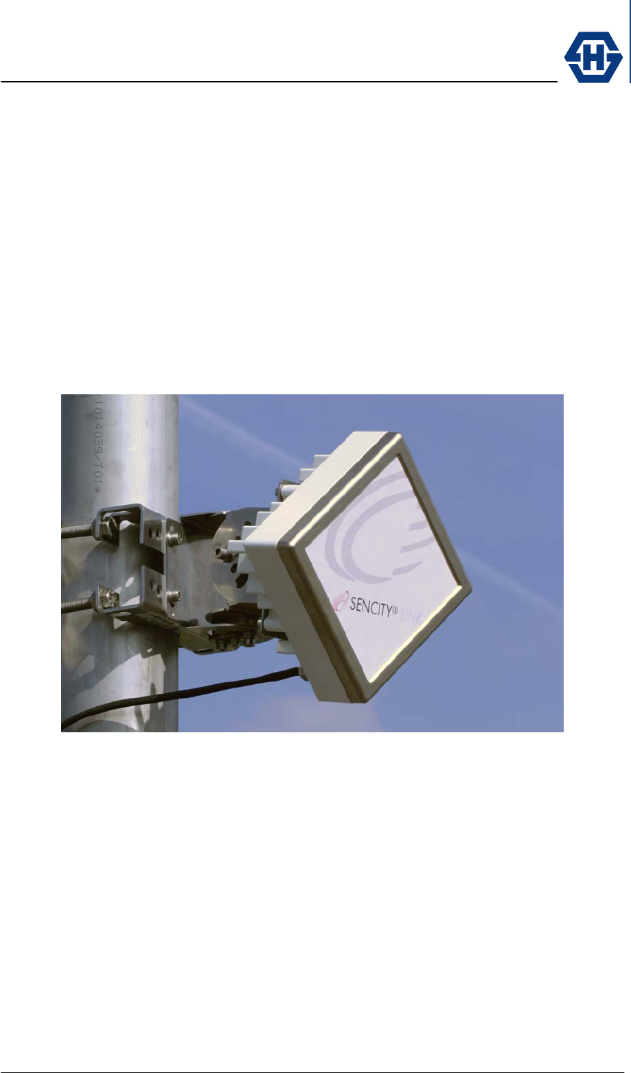
2.1 General Description
The system SL60-100-57/64-38-E-O operates as a data link in the 60 GHz
unlicensed band between 57 GHz and 64 GHz with a full duplex data rate of 100
Mbps over a distance of up to 1 km (3300 ft). In view of the unlicensed status of this
band, a Federal Communications Commission (FCC) license or special authorization
is not required to operate systems in the US.
Measuring only 16 × 16 cm (6.3" × 6.3"), its compact size is attained by extensively
integrating the active and passive components. The use of Power over Ethernet
(PoE), the optical alignment tool and the mounting bracket reduce the installation
effort to a minimum.
BLOCK DIAGRAM WITH BASIC FUNCIONALITY
2.2 System Components
The system SL60-100-57/64-38-E-O is composed of the following parts.
1. ODU
2. Alignment bracket
3. main accessories
♦ PoE injector
♦ Lightning Protector
♦ Alignment tool
♦ Mast bracket
♦ Hole template
♦ Watertight Ethernet cables
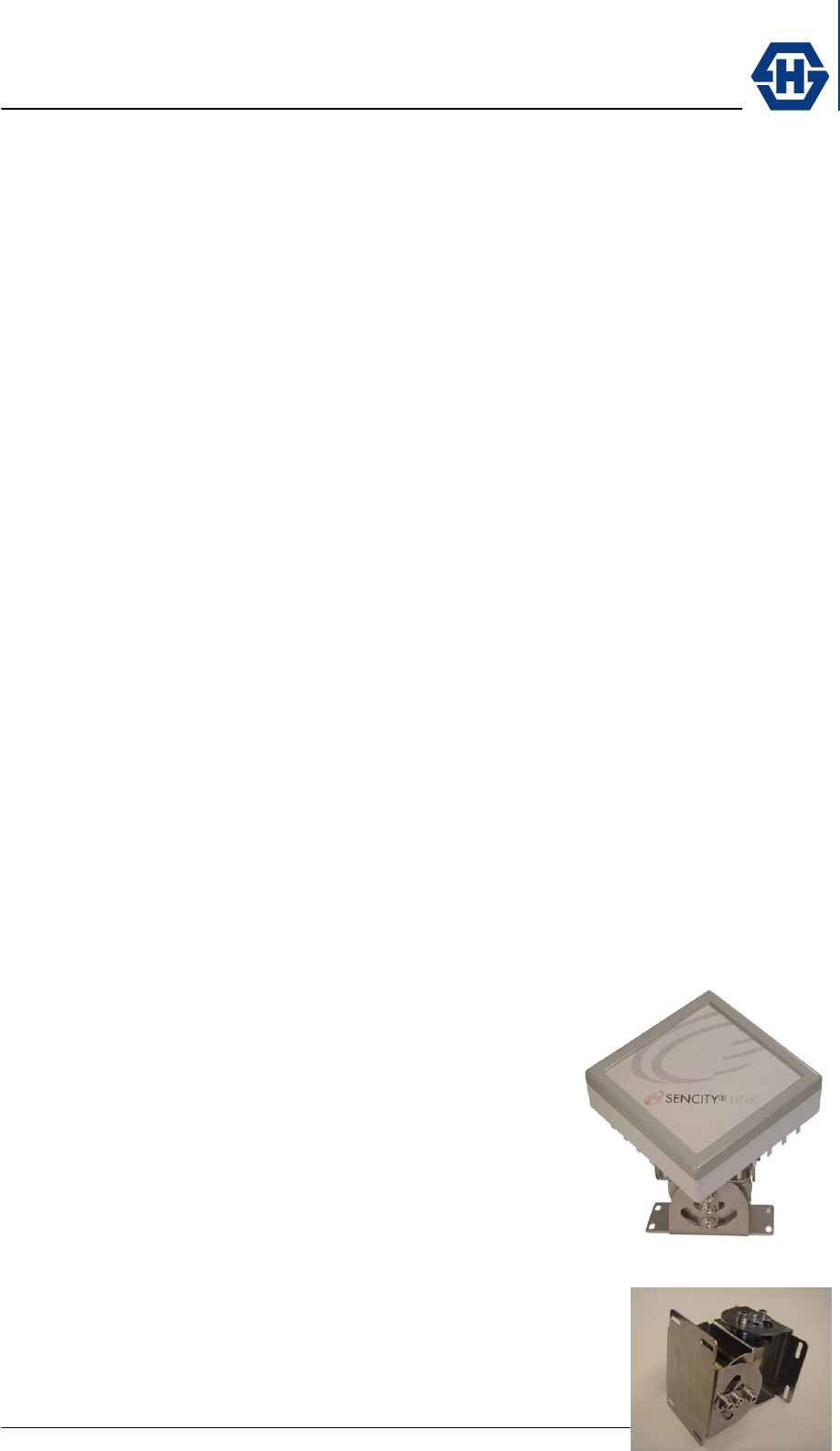
2.2.1 Outdoor Unit (ODU)
The ODU is the main component of the system. It
combines the antenna, transmitter and receiver and is
connected to the network through a standard Ethernet
cable with a RJ-45 connector. A water tight outdoor field
attachable RJ-45 connector is enclosed.
Power will be supplied through the Ethernet cable to the
ODU. This will need either a PoE (802.3af) compatible
router or an extra PoE injector.
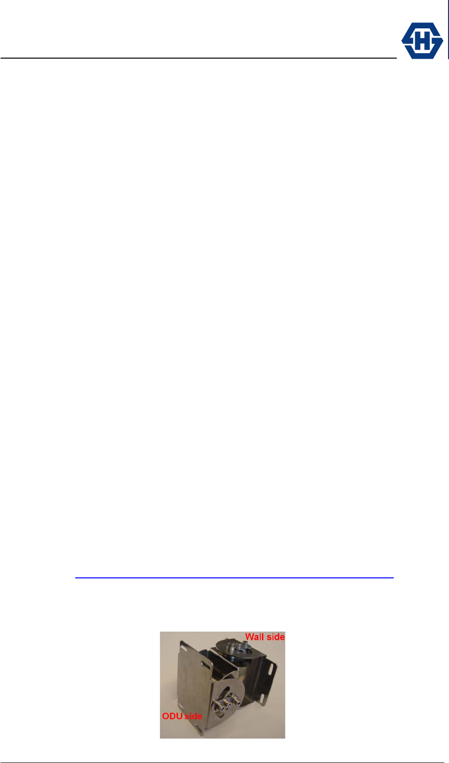
2.2.2 Mounting Bracket
The mounting bracket provides ease of installation and
pointing, by the use of independent axis course and fine
adjustment.
SL60-100-57/64-38-E-O - Installation and Service Manual
DOC-0000232377 Page 8 of 31 Issued: 29.08.05
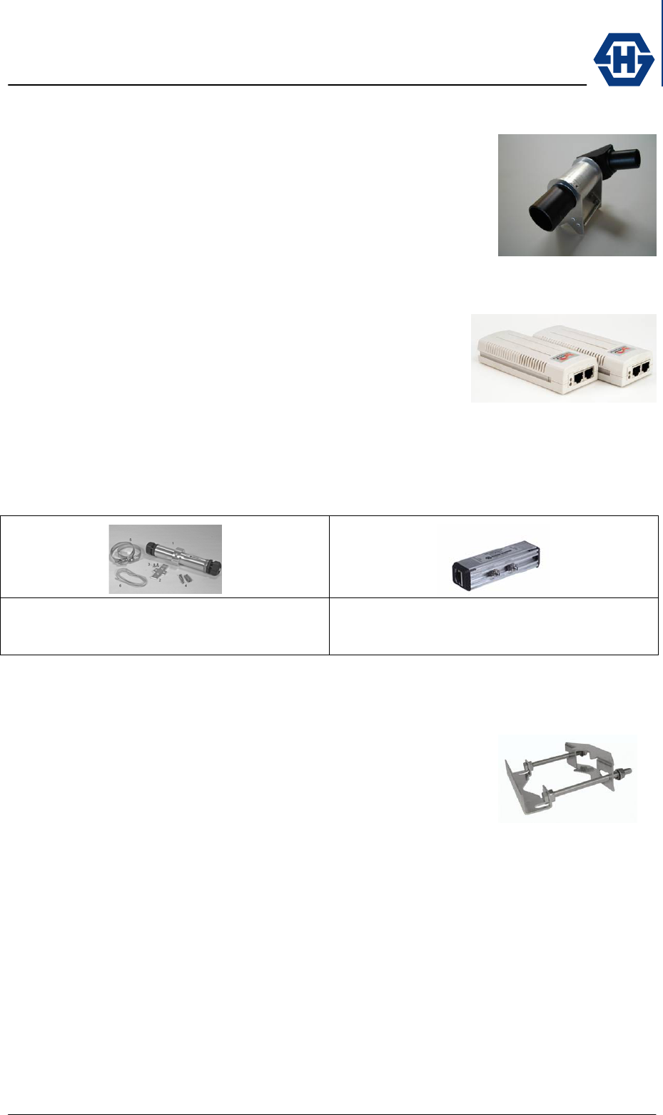
2.2.3 Alignment Tool
An optical alignment tool is provided that easily mounts to the
radio unit with a Velcro fastener. By using this optical tool, the
ends of the link can be quickly and simply aligned.
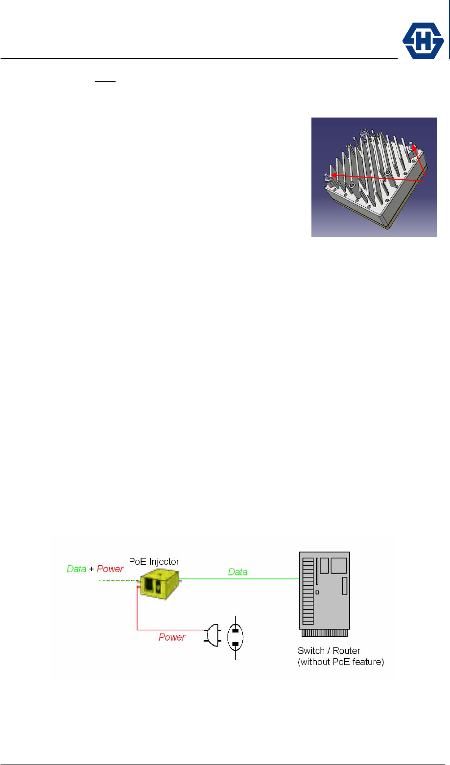
2.2.4 PoE Injector
The ODU is powered via Ethernet cable according to PoE
standard IEE 802.3af. If the router or switch connected to
SencityLink does not provide PoE, a Power Injector can be
inserted in line into the Ethernet cable. It is suggested that
the recommended PoE supply be used whenever possible.
2.2.5 Data Line Protector
HUBER+SUHNER strongly recommend the installation of Data Line Protectors to
provide lightning and surge protection to the building, personnel and equipment.
Outdoor version
HUBER+SUHNER type 3414.99.0008
Indoor version
HUBER+SUHNER type 3414.99.0001
2.2.6 Mast Bracket
The mast bracket (H+S type) is used to mount the bracket
onto a mast. The bracket is suitable for pole diameter from
2.36” to 5.12” (60 -130 mm).
2.2.7 Ethernet Cables
The length of the cable from the SencityLink to the Router/Switch can be up to 100
meters (328 ft) in length, but should be kept as short as practical in order to reduce
signal loss. All Ethernet cables must be CAT 5e compliant and suitable for outdoor
use. The cable must be UV stable, UL approved and must comply with local and/or
national building codes.
2.2.8 Accessories
2.2.9

SL60-100-57/64-38-E-O - Installation and Service Manual
DOC-0000232377 Page 9 of 31 Issued: 29.08.05
3 Site Planning
It is necessary that the installer performs an inspection of the site and plans the
installation prior the physical installation of SL60-100-57/64-38-E-O.
This inspection and planning tasks include:
♦ Evaluate the appropriate location for the installation of the links (see
section 3.1).
♦ Identifying an appropriate mounting structure (wall or mast) for each link.
♦ Planning the cable routing from your network component to the link.
♦ Setting up the proper network configuration for the links (see 4.9)
3.1 Line of Sight
Radio transmission requires a clear path between antennas known as radio line of
sight (LOS). To have a clear line of sight there must be no obstructions between the
two locations. The clearance necessary to operate can be established visually. The
following table helps to decide if an obstacle interferes with the radio line of sight
requirements.
link distance
[m]
link distance
[ft]
Boundary diamete
r
[m]
Boundary diamete
r
[ft]
100 328 0.4 1.2
400 1312 0.7 2.3
600 1968 0.9 2.8
800 2625 1.0 3.3
1000 3281 1.1 3.7
3.2 Radio Location
When selecting the best link location the following factors should be considered:
• Accessibility (roof, etc.)
• Type of mounting (wall / pole)
• Grounding connection point (see 3.6)
• Cable runs (max. 100m)
• Line of sight (see 3.1)
3.3 Link Distance / Link Availability
The link distance or separation between the link ends is directly related to the
tolerable BER (Bit error rate) and path availability.
The influence of BER on Ethernet transmission depends on the size of the
transmitted packets and their bit sequence. A rough rule of the thumb says good
Ethernet connections can be achieved with 10-6 BER.
The affordable link availability is influenced by following environmental conditions:
• Rain the lesser the better
• Temperature the higher the better
SL60-100-57/64-38-E-O - Installation and Service Manual
DOC-0000232377 Page 10 of 31 Issued: 29.08.05
• Air Pressure the lower the better
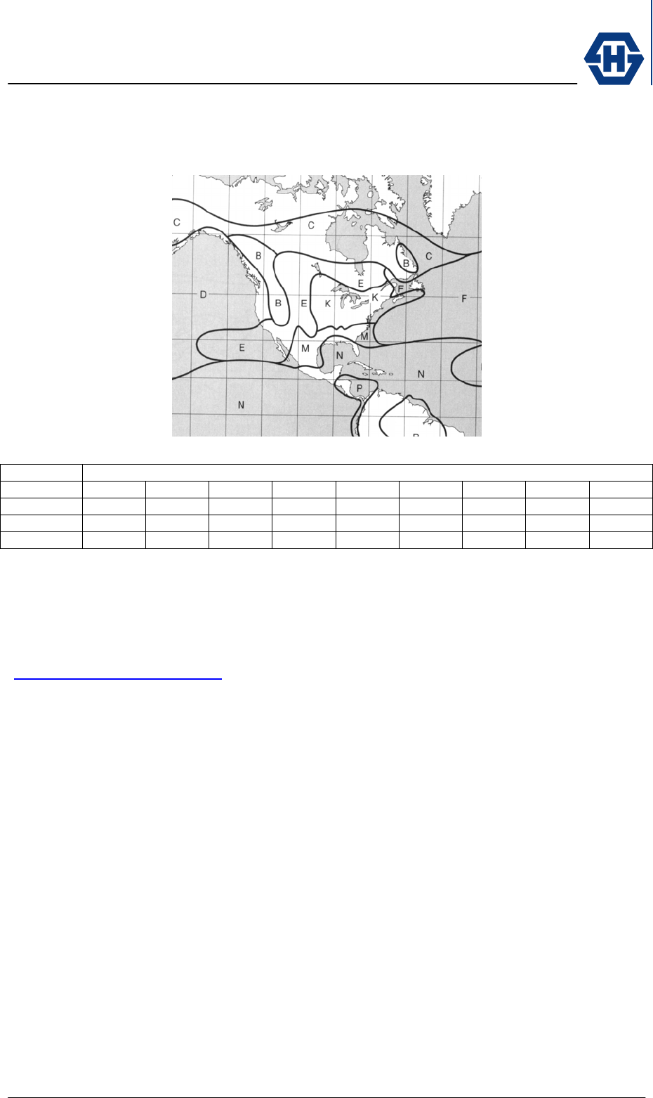
To the first order, the relationship of availability and link distance (line of sight) is
shown in the map below.
Availability Rain Zone*
A B C D E F K M N
99.900% 1014 996 963 923 949 923 877 791 711
99.990% 923 877 848 814 791 751 676 597 514
99.999% 791 727 676 676 575 554 504 468 391
* rain zone according ITU-R Recommendation PN.837
99.900% availability equates to 526 minutes per year of outage due to heavy rains.
99.990% availability equates to 53 minutes per year of outage due to heavy rains.
99.999% availability equates to 5 minutes per year of outage due to heavy rains.
For a more accurate link distance vs. availability number please visit our website
(www.hubersuhner.com/sl60), where you will find an online calculation tool.
Knowledge of the link distance (line of sight) is important in estimating the link quality.
The web browser based configuration software calculates the quality of the link by
using the entered link distance (line of sight).
3.4 Radio Mounting Options
Wall mounting
Use appropriate mounting bolts to mount the radio bracket to a wall mount location. A
drilling template is provided in order to properly locate the wall mounting hole
locations. The wall mounting location should be strong enough to secure the radio to
the wall under all foreseeable environmental conditions (wind, rain, ice, etc).
Depending on the material that the bracket is mounted to, different sized mounting
hardware may be necessary.
Pole mounting
The pole mounting kit (#23025718) can be used to mount the radio onto poles with
diameters between 2.36” to 5.12” (60 – 130 mm).
Radio mount on bracket

SL60-100-57/64-38-E-O - Installation and Service Manual
DOC-0000232377 Page 11 of 31 Issued: 29.08.05
To mount the terminal onto the bracket use the enclosed M6 bolts. It is important to
install the link on the bracket with the same orientation (antenna polarization) at both
ends of the link.
3.5 Cabling
The unit is delivered with a Ethernet cable terminated with a weather-proof RJ45
female connector. To connect the SencityLink to your network use a Ethernet cable
cat. 5e with a max length of 100 m. For outdoor use the enclosed Field Attachable
Connectors RJ45 connector. For outdoor use please verify that the cable used is
designed for outdoor environmental (water, solar UV, etc. applications). Because the
power is supplied by the Ethernet cable (POE), please confirm that the used switch
or router supports Power over Ethernet. If the switch/router does not provide PoE,
please use a POE injector. The PowerDsine model 3001 is recommended as supply
(see accessory).
3.6 Grounding / Lightning Protection
The radio must be properly grounded to provide protection against voltage surges. In
the event of a short circuit or lightening strike, proper grounding can prevent damage
to building, infrastructure and personnel.
For installations in the U.S.A. refer to Articles 830 of the National Electrical Code
(Network-powered broadband communications systems).
For installations in all other countries, implement protection in accordance with the
safety standards and regulatory requirements of the country where the equipment is
to be installed.
HUBER+SUHNER strongly recommend the use of lightening protectors. For
installation details see 4.7.
SL60-100-57/64-38-E-O - Installation and Service Manual
DOC-0000232377 Page 12 of 31 Issued: 29.08.05
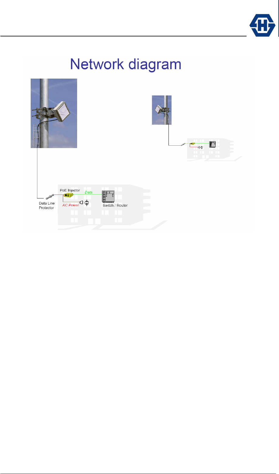
3.7 Network Diagram
3.8 Co-located Applications
Due to the small size of the SencityLink integrated terminal, it is particularly suitable
for co-sited applications. Some possible configurations are given below:
• Back-to-back to double the link distance
• Parallel link double the data capacity, redundancy
• Star point to multipoint
To deploy a co-sited application please contact HUBER+SUHNER to assist with the
proper site design.
SL60-100-57/64-38-E-O - Installation and Service Manual
DOC-0000232377 Page 13 of 31 Issued: 29.08.05
4 Installation
Due to the small size and integrated design of the SencityLink, the proper installation
and setup is relatively simple.
Nevertheless, when working on a roof, ladder, mast or staging, please use extreme
caution. Observe all facility and OSHA (or other applicable regulatory agency)
required safety precautions.
4.1 Unpacking
The whole equipment and installation material is packed into one box. Within the
main box there are three carton with following content:
Carton A: radio A
bracket
screws and socket wrench
power injector (accessory)
lightening protector (accessory)
field attachable RJ45 connector (accessory)
Carton B: radio B
bracket
screws and socket wrench
power injector (accessory)
lightening protector (accessory)
field attachable RJ45 connector (accessory)
Carton C: alignment tool (accessory)
manual
4.2 Mount Installation
Wall mount
• The wall and mounting screws must be able to support a weight of 11 pounds
(5 kg) and the associated wind and potential ice loading factors.
To ensure the use of the right screws for the installation, HUBER+SUHNER
strongly recommends consulting the online Anchor System Advisor from
HILTI. (http://www.us.hilti.com/holus/modules/adansel/adas_main.jsp ).
• Position of the bracket mounting screws by using the enclosed mounting
template. Attention: Make sure that the mount is properly positioned in the
correct direction noted.
Mast mount
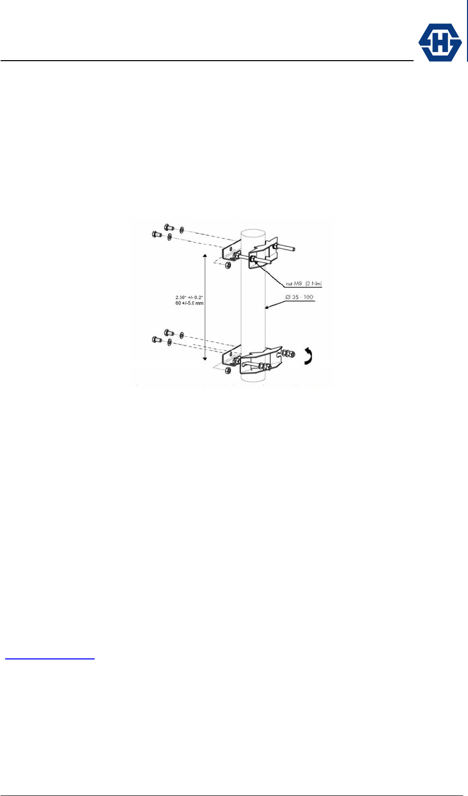
SL60-100-57/64-38-E-O - Installation and Service Manual
DOC-0000232377 Page 14 of 31 Issued: 29.08.05
• Ensure that the used mast has a diameter between 2.36” and 5.12” (60 -130
mm).
• Use a 17mm flat wrench (11/16”) to fasten the M8 screw nut.
• The distance between the mounting has to be 2.36” ±0.2” (60 ±5mm).
• To fasten the alignment bracket on the mast bracket use the enclosed
stainless steel screws, nuts and washer (M6). DON’T USE ZINK PLATED
SCREWS, which will cause corrosion.
4.3 Radio Installation
The ODU has to be mounted on the bracket in a way that the cable entry is on the
same side, top or bottom.
The ODU must be mounted on the bracket by using the enclosed stainless steel
screws (M6x12) with the socket driver. DON’T USE ZINK PLATED SCREWS, which
will cause corrosion.
4.4 Cable Installation
The length of the cable from the SencityLink to the Router/Switch can be up to 100
meters (328 ft) in length, but should be kept as short as practical in order to reduce
signal loss. All Ethernet cables must be CAT 5e compliant and suitable for outdoor
use. The cable must be UV stable, UL approved and must comply with local and/or
national building codes.
To enter the building HUBER+SUHNER recommend to use cable seals from Roxtec
(www.roxtec.com).
SL60-100-57/64-38-E-O - Installation and Service Manual
DOC-0000232377 Page 15 of 31 Issued: 29.08.05
4.5 Antenna Alignment
An outstanding property of SencityLink is the
easy and fast alignment procedure.
The radios can be aligned optically by using the
alignment tool. No electrical alignment is
required.
The table below shows the precision needed for
a proper link operation.
link distance
[m]
link distance
[ft]
spot diameter
[m]
spot diameter
[ft]
100 328 0.9 2.9
400 1312 3.5 11.5
600 1968 5.2 17.2
800 2625 7.0 22.9
1000 3281 8.7 28.6
1200 3937 10.5 34.4
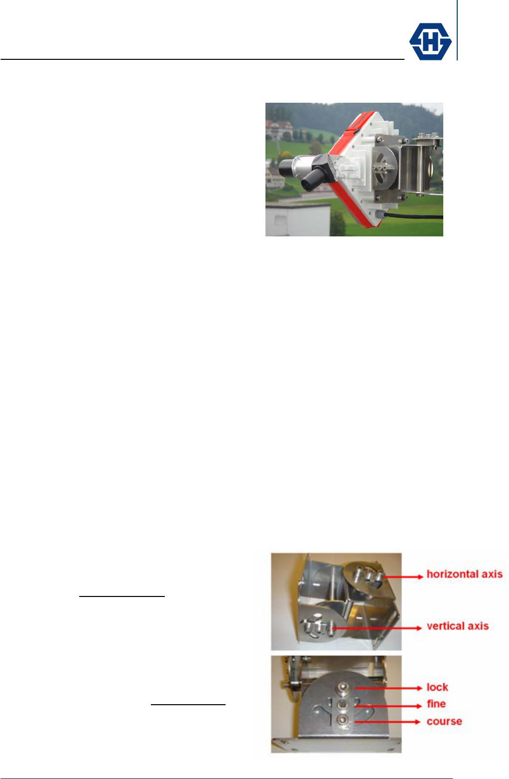
4.5.1 Alignment Procedure
The following procedure is used to achieve a fast and precise alignment (for all
operations the enclosed 5mm socket driver can be used).
(1) Mount the alignment tool on the most reachable edge of the ODU.
(2) place the course screw of the
horizontal axis in the middle position
(needle)
(3) make a rough alignment on the
horizontal axis and fasten the fine
screw
(4) repeat step (1) and (2) for the vertical
axis
(5) Turn the course screw of the
horizontal axis by viewing trough the
telescope and do the fine alignment.
(6) repeat (5) for the vertical axis
(7) If necessary repeat the fine alignment
procedure (5) for both axis till the
opposite link is pointed.
SL60-100-57/64-38-E-O - Installation and Service Manual
DOC-0000232377 Page 16 of 31 Issued: 29.08.05
(8) Fasten the lock screw on the horizontal and vertical axis.
4.6 Grounding
The radio must be properly grounded.
On the back housing of the ODU screws are provided to
properly ground the radio. To fasten the grounding cable
onto the ODU, use a lug and serrated washer combined
with M8 nut. Use isolated, corrosion resistant cable with
min 14AWG and connect the ODU to the nearest
connection points for the building-to-earth ground point.
The grounding conductor has to be as short as
practicable and typically not exceed 20 ft (6m).
For installations in the U.S.A. refer to Articles 830 of the National Electrical Code
(Network-powered broadband communications systems).
For installations in all other countries refer to the safety standards and regulatory
requirements of the country where the equipment is to be installed.
4.7 Lightning / Surge Protector
HUBER+SUHNER strongly recommend the use data line protectors.
One protector has to be installed near the ODU and a second protector must be
installed where the cable enters the building. For detailed installation instruction
please refer to the dedicated document:
Outdoor protector 3414.99.0008 84016716
Indoor protector 3414.99.0001 23033695
4.8 Power Injector
The power injector is connected inline with into the data line. The maximum distance
between PoE and SencityLink is 100m (328 ft). The PoE must be IEEE802.3af
compliant. To check the proper function of the injector, use the PoE Tester (see
accessory).
Grounding
screws
(
M8
)
SL60-100-57/64-38-E-O - Installation and Service Manual
DOC-0000232377 Page 17 of 31 Issued: 29.08.05
4.9 Network Configuration / Unit Control Functions
SL60 is using a single wire approach for Data, Control and Power of the unit.
External interface is the RJ45 connector allowing all the above mentioned
functionalities.
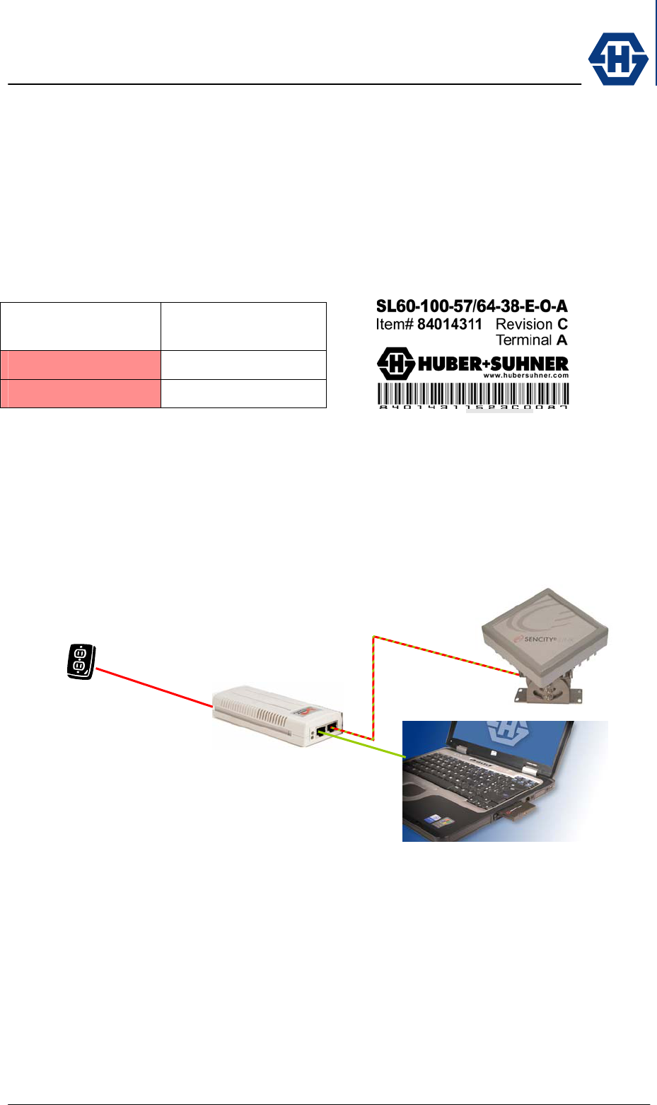
Controller functionality can be addressed with the manufacturer specific default IP
address mentioned below. The distinction of the A/B-unit can be made either on the
packing box or on the unit label shown below.
Manufacturer
Default IP address
Terminal A 192.168.042.011
Terminal B 192.168.042.012
For an initial configuration use PC or laptop in the below displayed configuration.
Address the SL60 unit with the above mentioned IP address corresponding to the
SL60 unit. To communicate with the unit make sure that the IP address of the used
computer is not allocate automatically by the DHCP server. Enter manually the IP
address e.g. 192.186.042.001 with subnet mask 255.255.255.0. Also make sure that
your Browser is not using any Proxy server.
SL60-100-57/64-38-E-O - Installation and Service Manual
DOC-0000232377 Page 18 of 31 Issued: 29.08.05
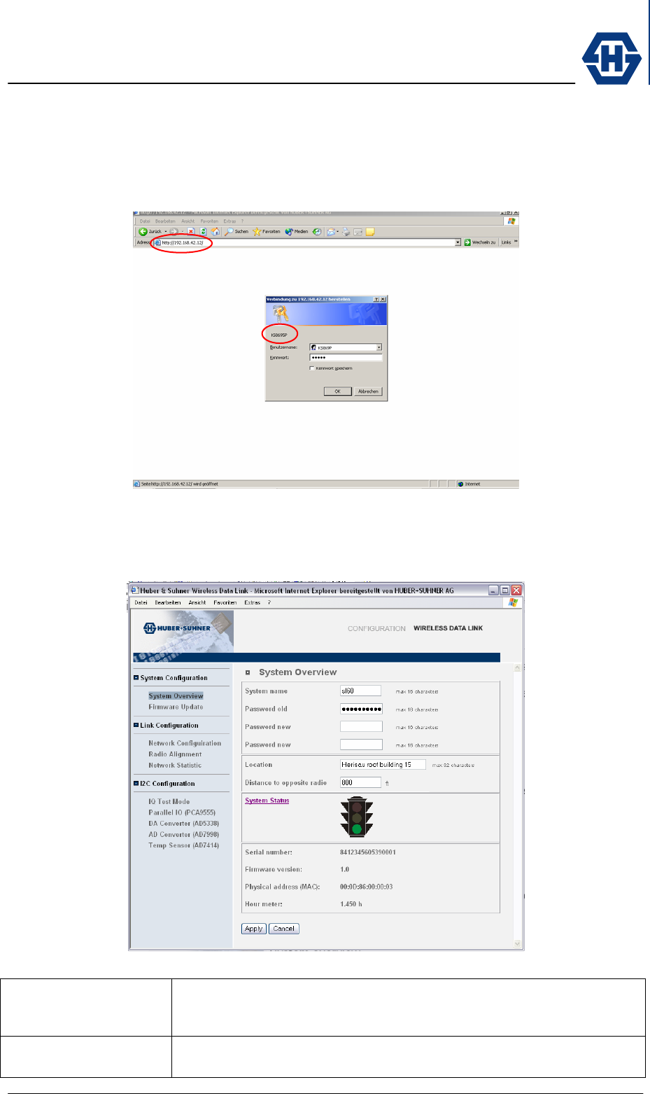
4.9.1 Password Screen
Using the above mentioned IP address you get access to the password screen. The
User Name is showed above e.g. KS6453 and the default password is “admin”. By
entering correct this information you get access to the System Overview screen.
4.9.2 System Overview Screen
This screen is giving a rough overview of the link and its status. In case of installation
problems please set up this page before calling.
System name Identifier for the system which max length is limited to 16 characters.
Identifiers will help you to better distinguish your links in a complicated
network structure.
Password old In case changing the system password, enter first the old password. The
manufacturer default the password is : "SencityLink60"
IP address of the unit
User name of the unit
SL60-100-57/64-38-E-O - Installation and Service Manual
DOC-0000232377 Page 19 of 31 Issued: 29.08.05
Password new In case changing the password use the first new window to enter the new
password. Confirm the new password in the below new labeled field
Location Describe the location either with address, building number or by using
absolute geographical data like longitudinal / latitudinal position.
Distance to opposite
radio
Define distance between A and B radio by using maps or distance
measurement equipment end enter data. Distance will be used to define
receive level determining the system status.
System status System is working fine, incoming signal is detected and
synchronized
System is working, periodical detection and synchronization, but
system performance need to be improved.
System is not functional. Detection or sychronisation is not
functioning.
Serial number Unique unit specific manufacturer serial number. For customer service
issues, please use this number as equipment reference.
Firmware version Firmware version defined by manufacturer. In case of upload the version
is automatically updated.
Physical address Unit specific MAC address defined by the manufacturer. Short for Media
Access Control address, a hardware address that uniquely identifies each
node of a network. In IEEE 802 networks, the Data Link Control (DLC)
layer of the OSI Reference Model is divided into two sub-layers: the
Logical Link Control (LLC) layer and the Media Access Control (MAC)
layer. The MAC layer interfaces directly with the network medium.
Consequently, each different type of network medium requires a different
MAC layer.
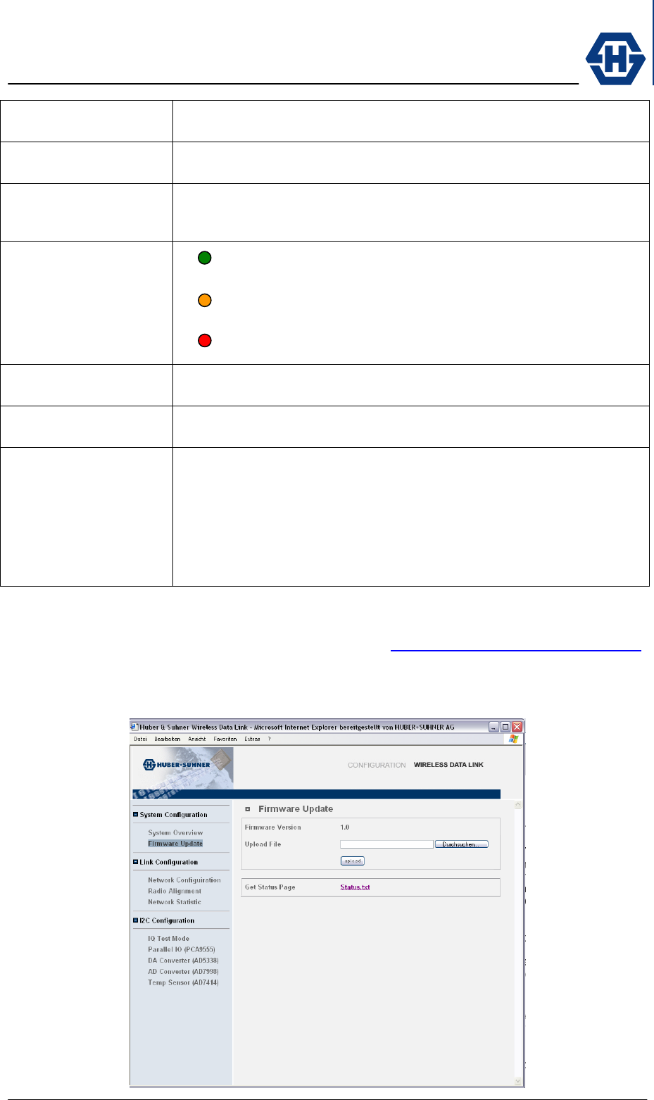
4.9.3 Firmware Update screen
Current firmware can be downloaded from Internet http://www.hubersuhner.com/sl60
or received from our technical support. The downloaded package should be saved on
the local network and can then be searched with the implemented search function
and uploaded into the unit.
SL60-100-57/64-38-E-O - Installation and Service Manual
DOC-0000232377 Page 20 of 31 Issued: 29.08.05
Firmware version Displays the currently loaded firmware version of the connected unit.
Upload file Downloaded Firmware can be traced with a search function or the direct
path and file information can be entered.
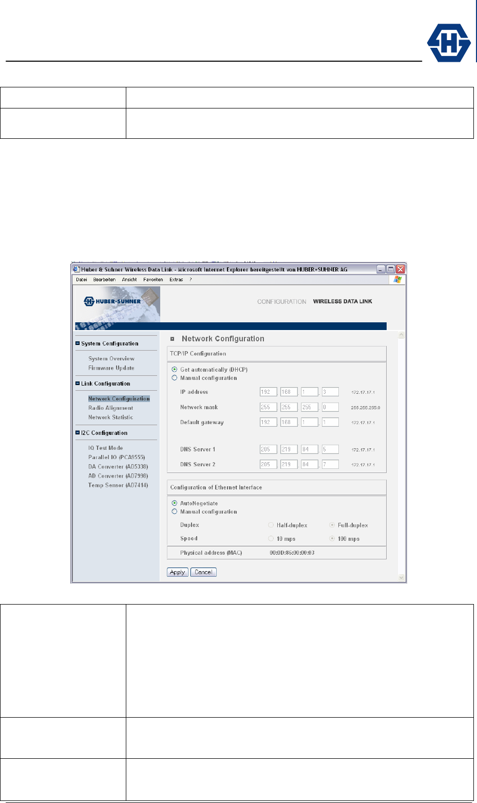
4.9.4 Network Configuration screen
The Network configuration screen is giving you the possibility to change network
settings if required. Use automatic network configuration (DHCP) and
AutoNegotiation in case you are not an advanced user.
Get automatically
(DHCP)
A protocol is automatically assigning dynamic IP addresses to the unit on
a network. With dynamic addressing, a device can have a different IP
address every time it connects to the network. DHCP ( Dynamic Host
Configuration Protocol ), also supports a mix of static and dynamic IP
addresses. Dynamic addressing simplifies network administration
because the software keeps track of IP addresses rather than requiring
an administrator to manage the task. This means your new installed and
connected unit can be added to a network without the hassle of manually
assigning it a unique IP address. Whenever possible use this setting.
Manual configuration
(IP)
In case you are not using DHCP you can manually set all the network
addressing parameters.
IP address An identifier for your device on a TCP/IP network. Networks using the
TCP/IP protocol route messages based on the IP address of the
destination. The format of an IP address is a 32-bit numeric address

SL60-100-57/64-38-E-O - Installation and Service Manual
DOC-0000232377 Page 21 of 31 Issued: 29.08.05
written as four numbers separated by periods. Each number can be zero
to 255. For example, 123.160.10.4 could be an IP address. Within an
isolated network, you can assign IP addresses at random as long as each
one is unique.
Network mask A Network mask is used to group IP addresses together. Routers use a
subnet mask to define the group (or IP subnet) to which an IP address
belongs so that it can identify the correct interface from which it should
forward an IP packet. Depending on the IP address range, type of
network and different sub-structures can be arranged. Below an example
of a C Class network number of 192.168.1.0,with some sub-networking
options :
No of No of
subnets Hosts/net netmask
2 126 255.255.255.128 (11111111.11111111.11111111.10000000)
4 62 255.255.255.192 (11111111.11111111.11111111.11000000)
8 30 255.255.255.224 (11111111.11111111.11111111.11100000)
16 14 255.255.255.240 (11111111.11111111.11111111.11110000)
32 6 255.255.255.248 (11111111.11111111.11111111.11111000)
64 2 255.255.255.252 (11111111.11111111.11111111.11111100)
Default gateway Enter the address of the default network device that will be used to
access another network. In enterprises, the gateway node often acts as a
proxy server and a firewall. The gateway is also associated with both a
router, which use headers and forwarding tables to determine where
packets are sent, and a switch, which provides the actual path for the
packet in and out of the gateway.
DNS Server 1 Address of the equipment providing DNS (Domain Name System)
services which translates domain names into IP addresses. Because
domain names are alphabetic, they're easier to remember. The network
however, is really based on IP addresses. Every time you use a domain
name, therefore, a DNS service must translate the name into the
corresponding IP address. For example, the domain name
www.example.com might translate to 198.105.232.4.
DNS Server 2 Address of an alternative equipment providing DNS (Domain Name
System) services.
Auto Negotiate Ethernet is basically capable to recognize its transmission protocol and
negotiates the necessary settings fully automatic. Whenever possible use
the AutoNegotiate setting.
Manual configuration
(Ethernet)
Is Auto Negotiate not possible use the manual setting options. Especially
older equipment is not using the auto negotiation capability.
Half-Duplex
(Duplex)
This device contain a switch that lets you select between half-duplex and
full-duplex mode. The correct choice depends on which protocol you are
using to transmit data through the link. In half-duplex mode, each
character transmitted is immediately displayed on the other end of the
link. (For this reason, it is sometimes called local echo -- characters are
echoed by the local device).
Full-Duplex
(Duplex)
Selection for duplex transmission mode. In full-duplex mode, transmitted
data is not displayed on the other end of the link until it has been received
and returned (remotely echoed) by the other device. If you are running a
communications protocol like Ethernet and every character appears twice,
it probably means that your device is in half-duplex mode when it should
be in full-duplex mode, and every character is being both locally and
remotely echoed.
SL60-100-57/64-38-E-O - Installation and Service Manual
DOC-0000232377 Page 22 of 31 Issued: 29.08.05
10mbps
(Speed)
Option button for local-area network (LAN) architecture developed by
Xerox Corporation in cooperation with DEC and Intel in 1976. Ethernet
uses a different topology and supports data transfer rates of 10 mbps.
The Ethernet specification served as the basis for the IEEE 802.3
standard, which specifies the physical and lower software layers. Ethernet
uses the CSMA/CD access method to handle simultaneous demands.
100mbps
(Speed)
Option setting for networking standard that supports data transfer rates
up to 100 mbps (100 megabits per second). 100BASE-T is based on the
older Ethernet standard. Because it is 10 times faster than Ethernet, it is
often referred to as Fast Ethernet. Officially, the 100BASE-T standard is
IEEE 802.3u.
Physical address
(MAC)
Unit specific MAC address defined by the manufacturer. Short for Media
Access Control address, a hardware address that uniquely identifies each
node of a network. In IEEE 802 networks, the Data Link Control (DLC)
layer of the OSI Reference Model is divided into two sub-layers: the
Logical Link Control (LLC) layer and the Media Access Control (MAC)
layer. The MAC layer interfaces directly with the network medium.
Consequently, each different type of network medium requires a different
MAC layer.
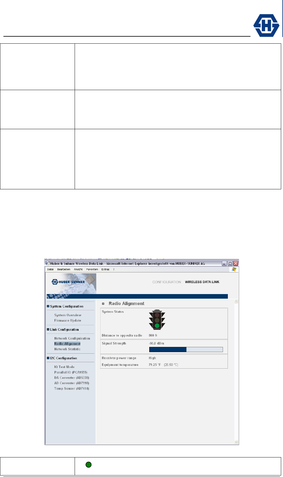
4.9.5 Radio Alignment screen
The Radio Alignment screen is giving you specific details for alignment of the two
radios. Since point to point radios have to have line of sight (LOS) conditions and
have to be pointed face to face to each other. This page provides you with all the
technical information necessary for the alignment process.
System status System is working fine, incoming signal is detected and
synchronized
SL60-100-57/64-38-E-O - Installation and Service Manual
DOC-0000232377 Page 23 of 31 Issued: 29.08.05
System is working, periodical detection and synchronization, but
system performance need to be improved.
System is not functional. Detection or sychronisation is not
functioning.
Distance to opposite
radio
Define distance between A and B radio by using maps or distance
measurement equipment and enter data. Distance will be used to define
receive level determining the system status.
Signal strength Absolute signal level in the receiving path of the device. The signal
strength is displayed also in a coloured bar indicating the signal strength
with the following values :
Signal < -100dB resulting in detection and synchronization
problems
Signal > -100dB resulting in periodical detection and
synchronization with possibility to improve system performance
Signal > -90dB resulting in good detection and synchronization
Transmit power level The status high or low is indicating if RX MPA is active or not. Rain fading
can trigger the equipment to additionally switch on MPA’s for better
receive level.
Equipment
temperature
Indication of temperature in the equipment. Typical temperature values
are 0 – 40°C or 32 – 104°F
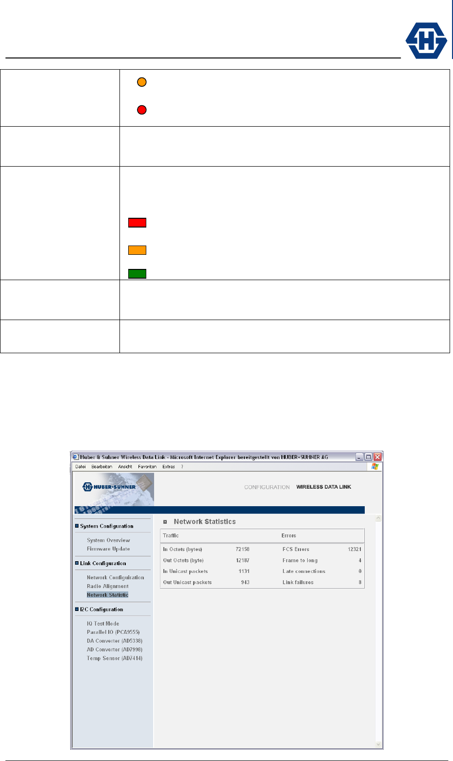
4.9.6 Network Statistics screen
The Network Statistic screen is giving standardized information about network traffic
and errors. Traffic status information is continuously updated and specific network
errors are listed.
SL60-100-57/64-38-E-O - Installation and Service Manual
DOC-0000232377 Page 24 of 31 Issued: 29.08.05
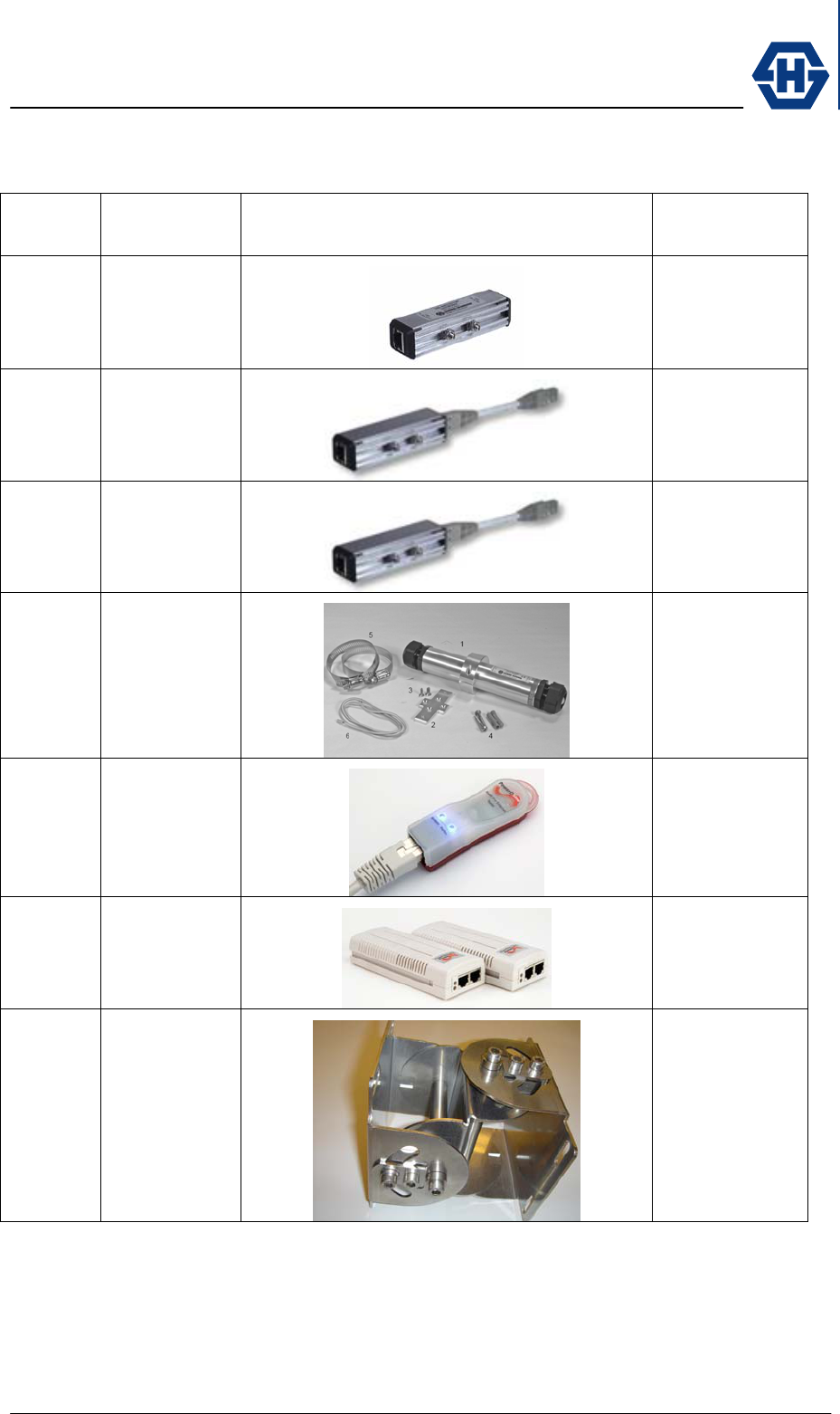
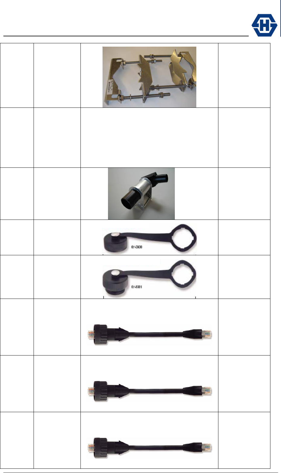
4.10 Optional items
ARTICLE
NO DESCRIPTION PRICTURE DATA-SHEET
23033695
Data Line
Protector
indoor
23xxxxx
Data Line
Protector
indoor
23xxxxx
Data Line
Protector
indoor
84014284
Data Line
Protector
outdoor
84021330
PoE 802.3af
Tester
84021333
PoE 802.3af
Power Injector
84016575
SL60
Alignment
bracket
SL60-100-57/64-38-E-O - Installation and Service Manual
DOC-0000232377 Page 25 of 31 Issued: 29.08.05
23xxxxxx
SL60
Mounting
bracket pole
20cm
23xxxxxx
SL60
Mounting
bracket back
to back pole
20cm
84016596
Visual
alignment tool
1000m
23xxxxxx
Protection cap
for Outdoor
RJ45 IP67
23xxxxxx
Protection cap
for Outdoor
RJ45 IP67
23xxxxxx
Cable Assy
RJ45 IP67
Male /
RJ45 IP40
Hybrid 3m
UV / UL rated
3m / 10ft
23xxxxxx
Cable Assy
RJ45 IP67
Male /
RJ45 IP40
Hybrid 5m
UV / UL rated
5m / 16ft
23xxxxxx
Cable Assy
RJ45 IP67
Male /
RJ45 IP40
Hybrid 10m
UV / UL rated
10m / 33ft
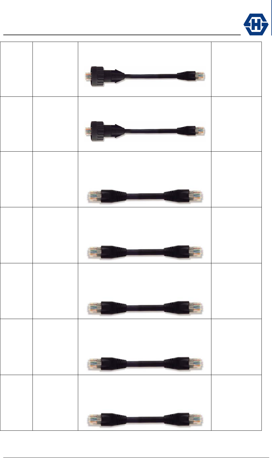
SL60-100-57/64-38-E-O - Installation and Service Manual
DOC-0000232377 Page 26 of 31 Issued: 29.08.05
23xxxxxx
Cable Assy
RJ45 IP67
Male /
RJ45 IP40
Hybrid 30m
UV / UL rated
30m / 98ft
23xxxxxx
Cable Assy
RJ45 IP67
Male /
RJ45 IP40
Hybrid 50m
UV / UL rated
50m / 164ft
23xxxxxx
Cable Assy
RJ45 IP40
Hybrid /
RJ45 IP40
Hybrid 3m
UV / UL rated
3m / 10ft
23xxxxxx
Cable Assy
RJ45 IP40
Hybrid /
RJ45 IP40
Hybrid 5m
UV / UL rated
5m / 16ft
23xxxxxx
Cable Assy
RJ45 IP40
Hybrid /
RJ45 IP40
Hybrid 10m
UV / UL rated
10m / 33ft
23xxxxxx
Cable Assy
RJ45 IP40
Hybrid /
RJ45 IP40
Hybrid 30m
UV / UL rated
30m / 98ft
23xxxxxx
Cable Assy
RJ45 IP40
Hybrid /
RJ45 IP40
Hybrid 50m
UV / UL rated
50m / 164ft

SL60-100-57/64-38-E-O - Installation and Service Manual
DOC-0000232377 Page 27 of 31 Issued: 29.08.05
5 Appendix
5.1 Specification
5.1.1 Receiver
5.1.2 Transmitter
5.1.3 Antenna
5.1.4 Mechanical
5.1.5 Environmental
5.1.6 Network Management
5.2 Troubleshooting
This Chapter provides solutions to problems that can occur during the installation and
operation of the SL60-100-57/64-38-E-O. We cover various aspects of the installation
and the network setup. Please read the following if you are having problems.
Note
You have to check all the following points at both ends of the Link. Start with
the whole procedure at one side (e.g. Terminal A) if the problem is not solved,
do all the steps at the opposite terminal.
5.2.1 Power and Network Connection
Î You have to verify that the terminal gets power. The PoE injector has to be
installed and plugged in according to the manual (VERWEIS). Go to the
terminal, disconnect the watertight RJ-45 connector and verify with a
standard PoE tester (VERWEIS) if there is power on the cable.
Î Take the cable and plug it into a notebook or a network testing device and
verify if there is a proper network connection.
If there is any problem, please replace the cable and validate the proper connection
again. We provide special preassembled outdoor CAT-5e cables to ensure a easy
installation.
5.2.2 Network Configuration
Î Check that the IP address is in the same range and subnet as the SL60-
100-57/64-38-E-O. Please see VERWEIS section of this manual.
Note:
The IP address of the SL60-100-57/64-38-E-O is 192.168.0.1 for terminal A
and 192.168.0.2 for terminal B. All the computers on the network must have a
unique IP address in the same range, e.g., 192.168.0.x. Any computers that
have identical IP addresses will not be visible on the network. They must all
have the same subnet mask, e.g., 255.255.255.0
SL60-100-57/64-38-E-O - Installation and Service Manual
DOC-0000232377 Page 28 of 31 Issued: 29.08.05
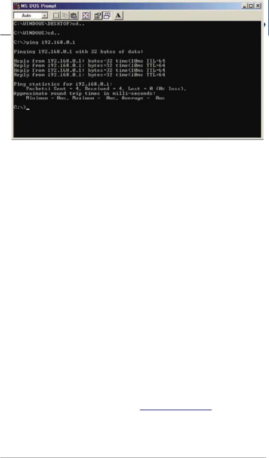
Î Do a Ping test to make sure that the SL60-100-57/64-38-E-O is
responding. Go to Start>Run>Type Command>Type ping 192.168.0.50. A
successful ping will show four replies. (GRAPHIK HIER PLATZIEREN)
As soon the network configuration is correct you can access the GUI
(Graphical User Interface) and check the settings according to section
VERWEIS
5.2.3 Duplex Mismatch
Î If you have bad network performance you have probably a Duplex
mismatch.
Î To ensure that the terminal of SL60-100-57/64-38-E-O and the connected
network component (e.g. switch) do not have a Duplex Mismatch you
check first your statistics. If you find many Input Errors, you are on the Full-
Duplex side, if you see many Late Collisions, you are on the Half-Duplex
side.
Î To solve the duplex mismatch you have to configure manually both
network components and to the same values.
5.2.4 Miss-alignment
Î Access the configuration interface as described in section VERWEIS. On
the page … you see the signal strength in dBm (e.g. -30 dBm). If the value
is below -65 dBm the receiver is not in the position to track the signal.
Therefore you need to re-align the terminal to its opposite terminal (please
follow the instructions at section VERWEIS).
5.3 Contacts
5.3.1 Technical Assistance
Please check the information on the website www.hubersuhner.com (müssen wir mit
Salesforce integriert lösen)
5.3.2 Service Center / RMA
Adresse vom Support der eine RMA ausgibt.

SL60-100-57/64-38-E-O - Installation and Service Manual
DOC-0000232377 Page 29 of 31 Issued: 29.08.05
6 Glossary
Abbreviation Description in detail
ADSL Asymmetric digital subscriber line. Typical data rate is 256-2Mbps
downstream and 128k upstream. See xDSL.
BAKOM Swiss Federal Communication Office (Bundesamt für
Kommunikation)
BDP Broadband data providers. Broadband data provision is not the core
business but existing infrastructure used to diversify or promote core
activity
BHU Broadband home user. Home User which is an early adopter of
technology.
CEPT European Conference of Postal and Telecommunications
Administrations
COM COMunities market segment including all community buildings like
administration, community hall, excluding all educational needs
DataCom Word created to summarise companies working in the data
communication area excluding pure computer manufacturer. Typical
companies are CISCO or PROXIM which strongly support Network-
and Data-Management business.
DHCP Dynamic Host Configuration Protocol DHCP allows manual and
automatic IP address allocation in a network
EDU EDUcation market segment containing all colleges, universities,
schools …
ETSI European Telecommunication Standards Institute
FBP Fixed broadband providers. Incumbent Providers having
telecommunication as core business providing rented or leased
broadband data lines to most of the time enterprise customers.
FCC Federal Communication Commission ( North America US )
FSO Free Space Optics. Free space lasers working in the range of 1.5nm
wavelength capable to transmit data of 100-2000 Mbps over a
distance of up to 1000m depending on the environment ( fog, rain, …
)
HOS HOSpital market segment including infrastructure of hospitals
ICMP Internet Control Message Protocol Messages released from routers if
irregularities accrue in the message flow
IDSL ISDN over DSL. Full duplex 144kbps. See xDSL.
IDU Indoor unit of the equipment hosting most of the time the data
processing unit, encryption and protocol adaptation to the
environment the link is use in
ISP Internet service provider. Private and semi-private providers of

SL60-100-57/64-38-E-O - Installation and Service Manual
DOC-0000232377 Page 30 of 31 Issued: 29.08.05
Abbreviation Description in detail
broadband internet access depending on the liberalisation of the
individual country.
LAN Local area networks
LE Large enterprises. In H+S terminology this are companies with more
then 100 employees and often having more then just one building in
the same location
LOS Lign of Sight ; visual contact of point to point without any interruption
LTCC Low Temperature Ceramic Co-fired
MAN Metropolitan area networks
MIMO Multiple Input Multiple Output
ODU Outdoor unit of the equipment. As minimum this could be an antenna,
as maximum it could be the total RF and data processing unit.
OFDM Orthogonal Frequency Division Multiplex
PoE Power over Ethernet according to IEEE 802.3af providing a
standardised powering model
QPSK Quadrature Phase Shift Keying
xQAM Quadrature Amplitude Modulation where x is indicating how many
amplitude/phase variations have been used to build the protocol
RAD Research and Advanced Development
RBS HUBER+SUHNER internal abbreviation for Radio base station
including the fully populated cabinet up to the first antenna feeder
jumper cables.
SDSL Symmetric digital subscriber line. Full duplex up to 2Mbps. See xDSL
SME Small and medium size enterprises or Business. In H+S we use the
threshold of 100 people to define the step to large enterprises. Below
11 people in H+S terms this would be a SOHO.
SNMP Simple Network Management Protocol
SOHO Small office and home office user. Office with 1-10 people. Most small
offices like home sales office or surgeries…
TL60 Transparent Link 60 GHz project name for technology development
VDSL Very High speed DSL. Possible 52Mbps downstream and up to
2Mbps downstream
WAN Wide Area Network
WLAN Wireless local area network. Today typically unlicensed application
non line of site in the frequency range 2-6 GHz according to IEEE
802.11x.
Wli Wireless link. A wireless link can use frequencies from 2-100GHz by
using different modulation and protocols.

SL60-100-57/64-38-E-O - Installation and Service Manual
DOC-0000232377 Page 31 of 31 Issued: 29.08.05
Abbreviation Description in detail
xDSL All digital subscriber line systems from ADSL, SDSL, IDSL and VDSL
which generally are derivatives of the technology. Main parameters
changed are the bandwidth which is varying from 128kbps to 52Mbps.
Another important parameter is the up/downstream ratio (asymmetric
to full duplex)
•2• Point to point configuration. Two transmitting / receiving units
connected via narrow beam antennas.
•2•• Point to Multipoint configuration. One central access point is
distributing a signal to several other points in a star configuration.