HUBER SUHNER SL606004 Microwave Link User Manual Installation and
HUBER+SUHNER AG Microwave Link Installation and
UserManual.wiki
>
HUBER SUHNER
>
SL606004 User Manual
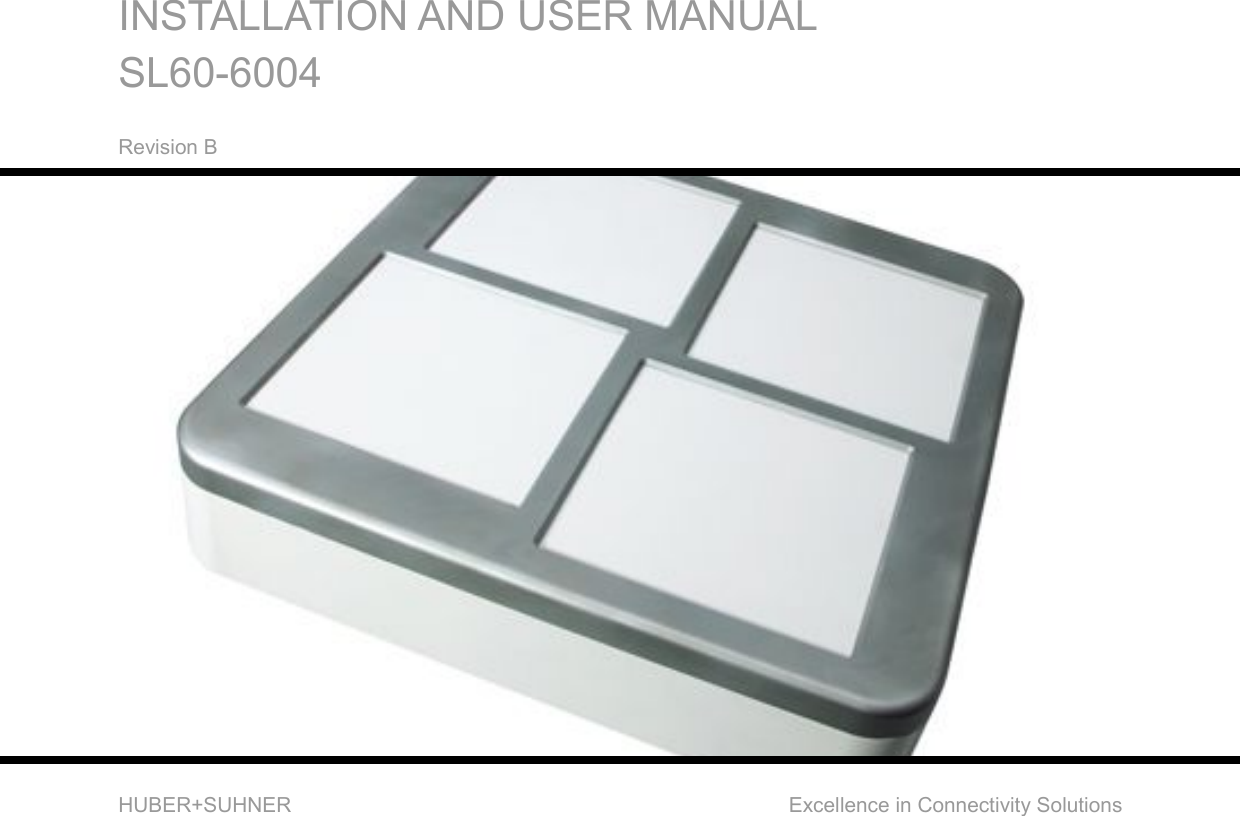
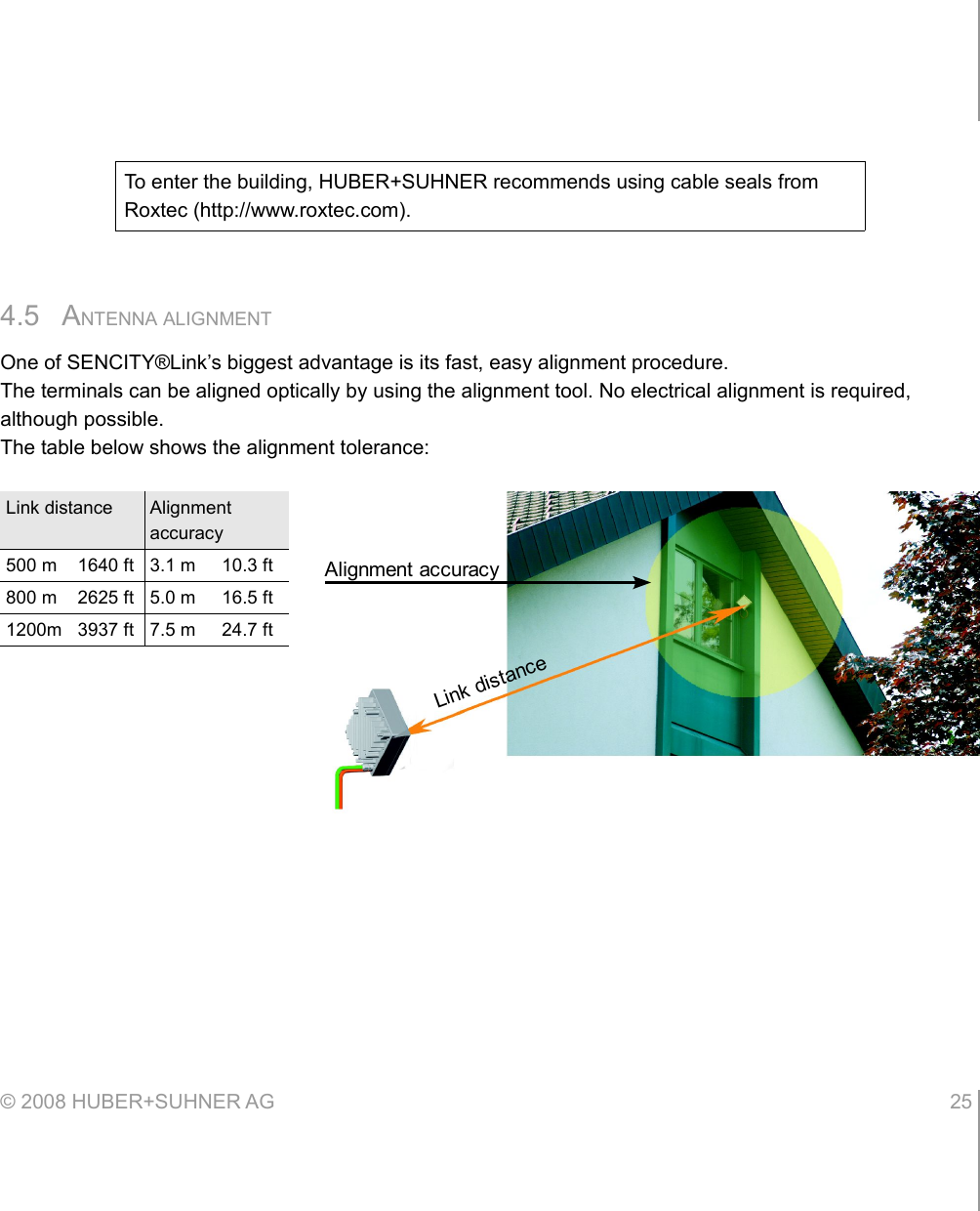
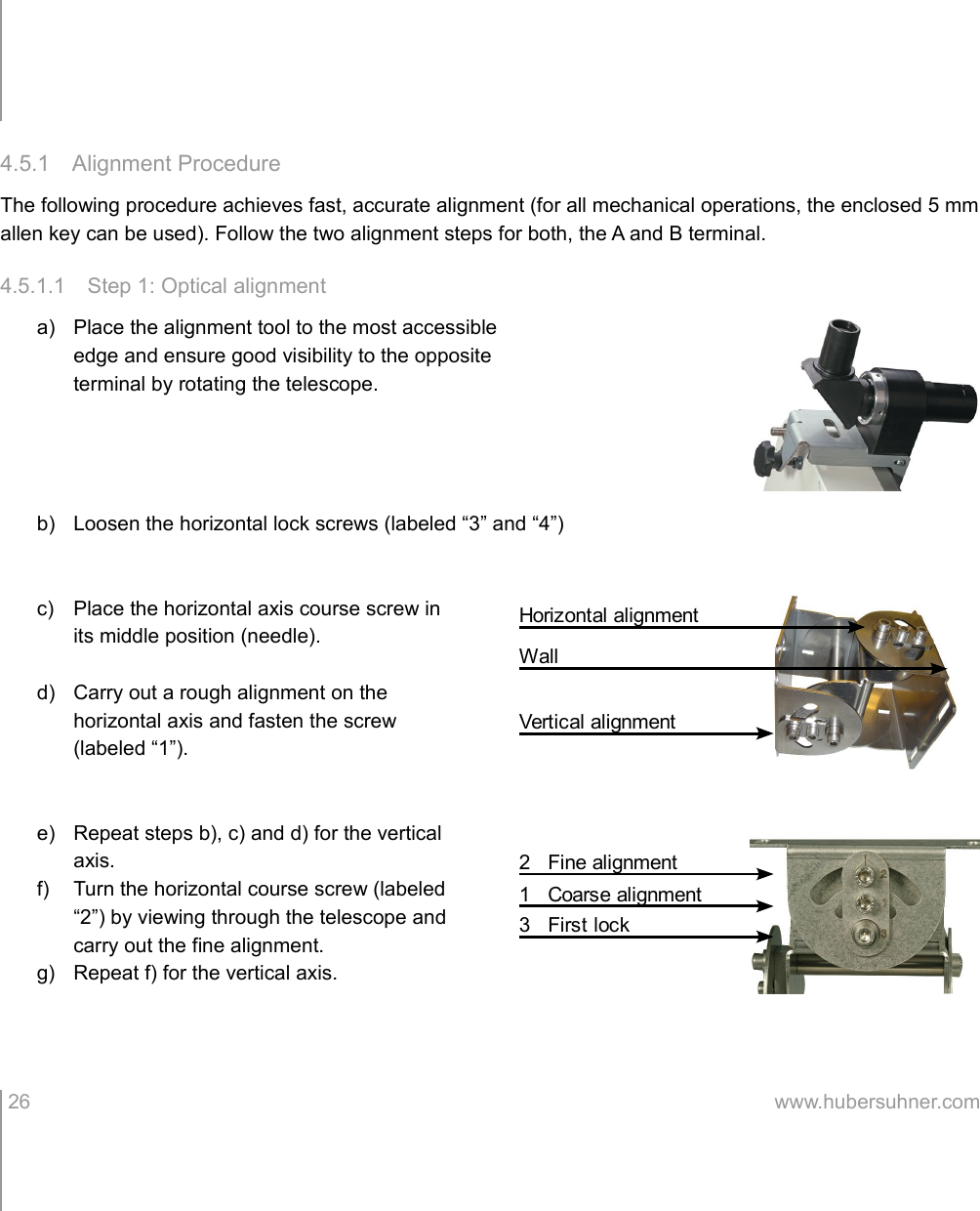
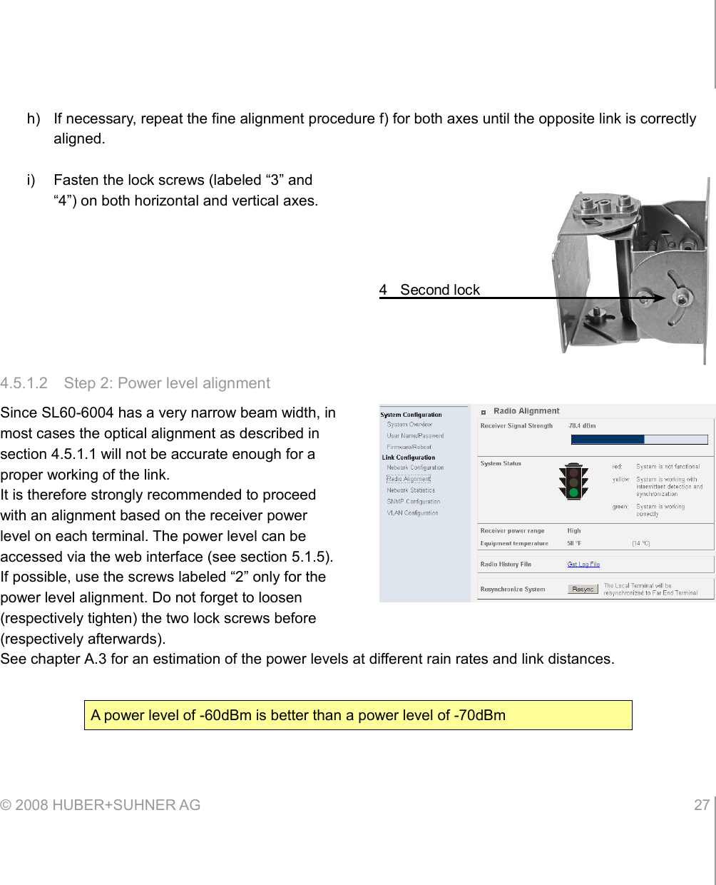
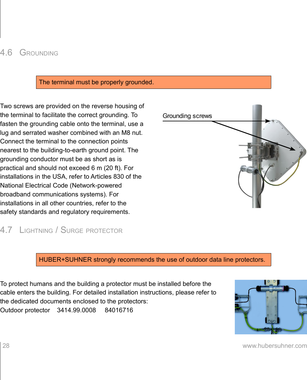
Installation and user manual
Navigation menu
Upload a User Manual
Namespaces
Wiki Guide
HTML
PDF
Info
Views
User Manual
Discussion / Help
Navigation
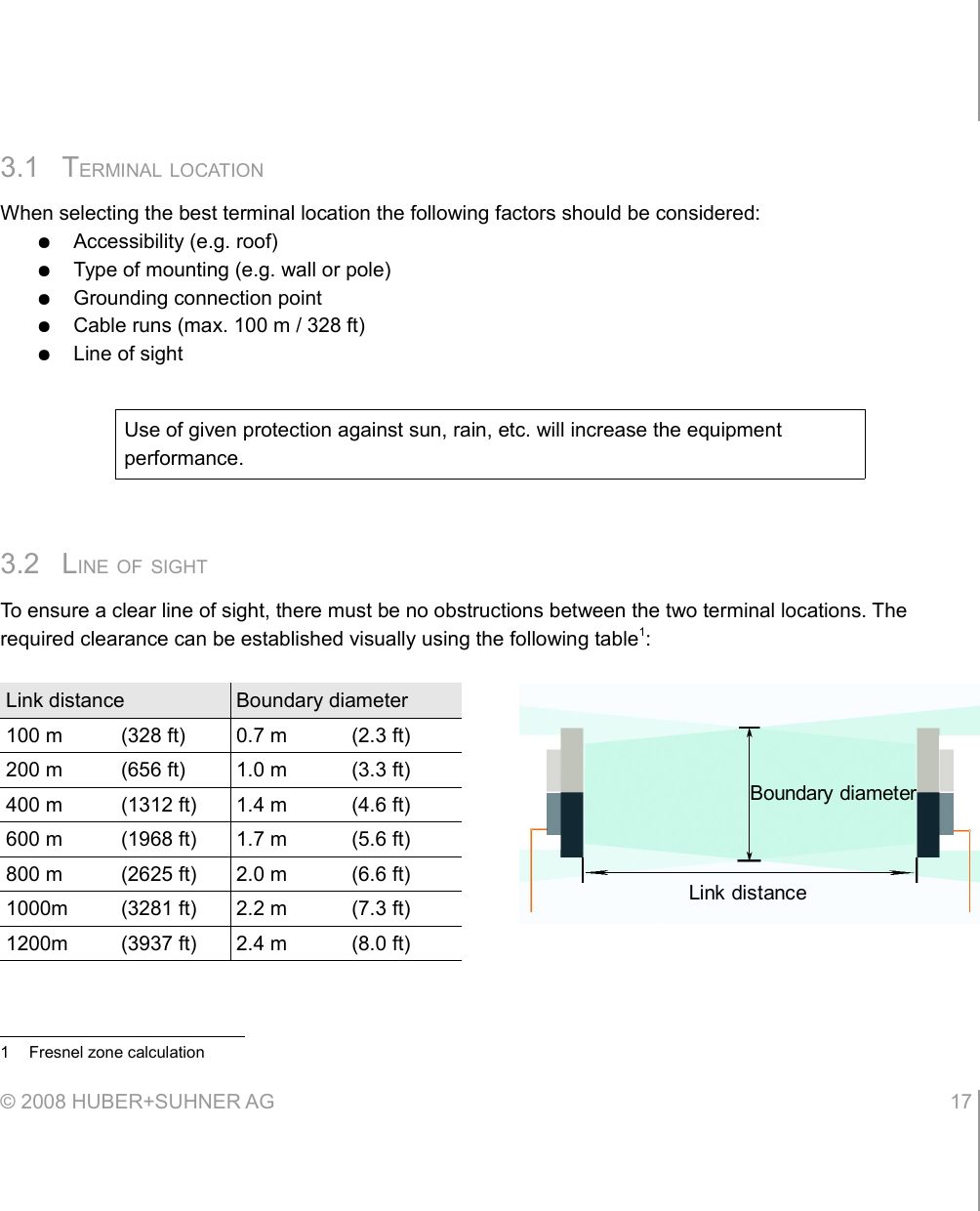
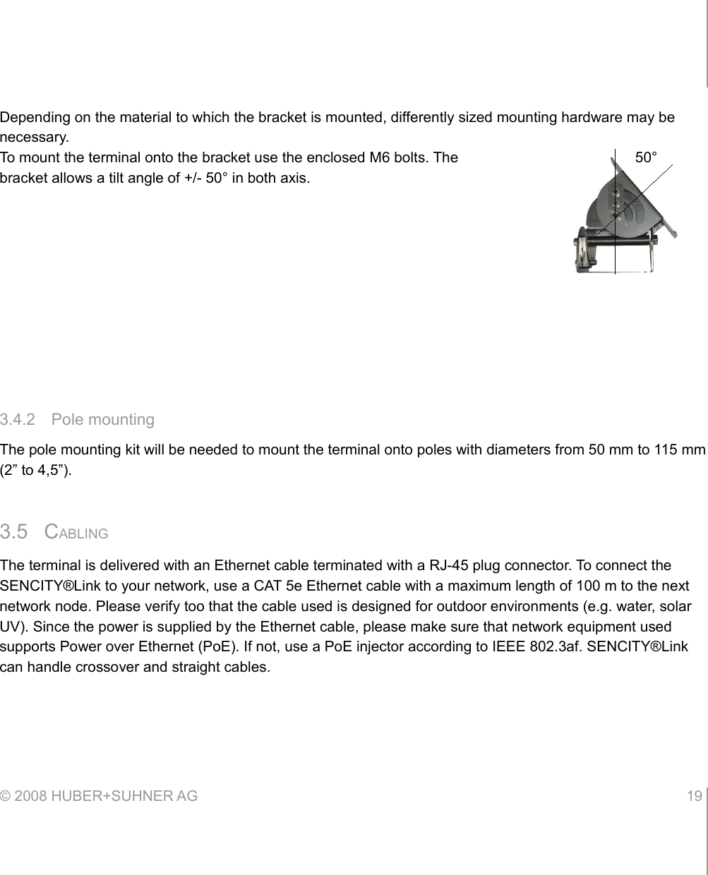
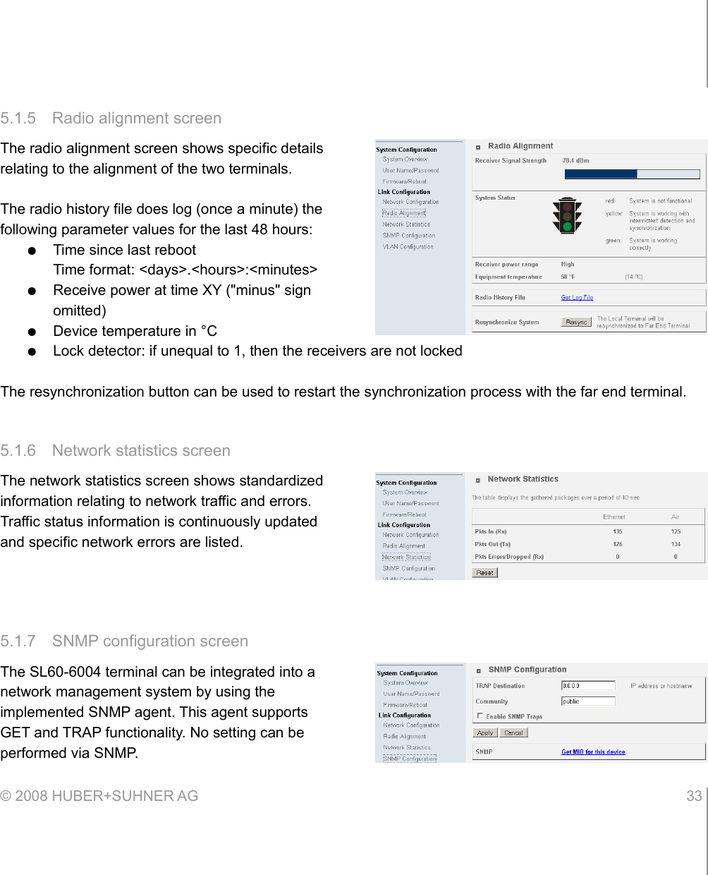
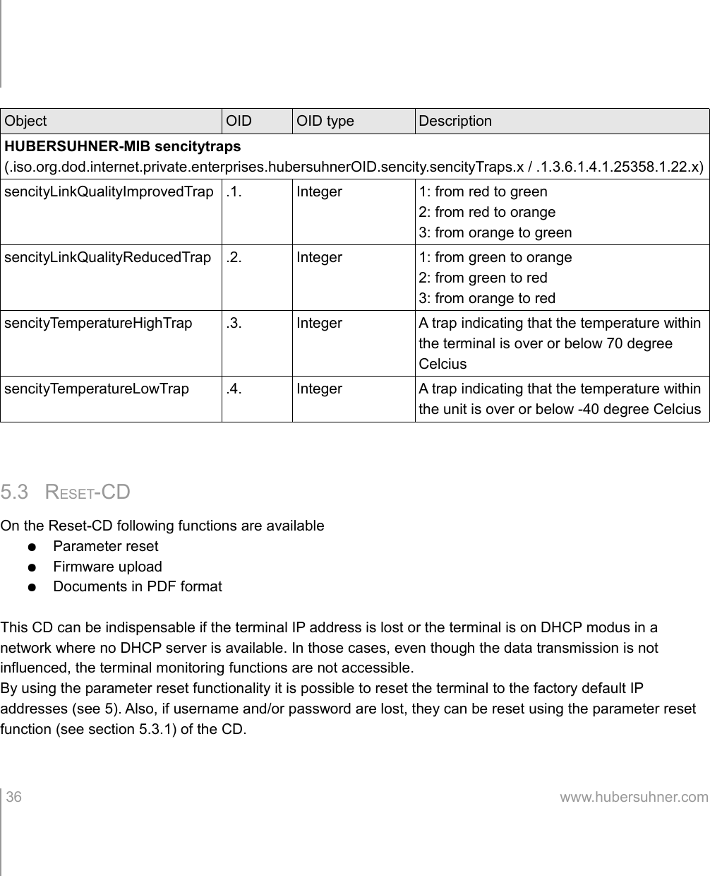
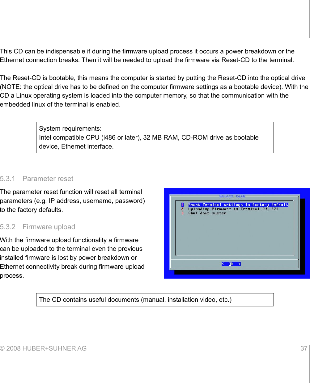
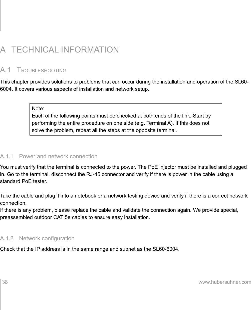
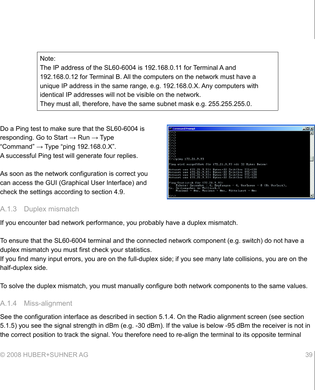
![5.2 SNMP INTERFACEObject OID OID type DescriptionMIB-2(iso.org.dod.internet.mgmt.mib-2.system.x / .1.3.6.1.2.1.1.x)sysDescr .1. DisplayString Includes serial no.sysUpTime .3. TimeTicks Uptime of the network managementsysName .5. DisplayString set in the web GUIsysLocation .6. DisplayString set in the web GUIHUBERSUHNER-MIB sencity(.iso.org.dod.internet.private.enterprises.hubersuhnerOID.sencity.x / .1.3.6.1.4.1.25358.1.x)sencityLinkQuality .1. Integer 1: Green2: Yellow3: RedsencityReceivePower .10. Integer Receive signal level [dBm]sencityTemperature .11. Integer Temperature [°C]sencityIfEthernetIn .15. Integer Total frames received on the Ethernet interfacesencityIfEthernetOut .16. Integer Total frames sent on the Ethernet interfacesencityIfEthernetInError .17. Integer Total frames dropped due to errors received on the Ethernet interfacesencityIfAirIn .18. Integer Total frames received on the Air interfacesencityIfAirOut .19. Integer Total frames sent on the Air interfacesencityIfAirInError .20. Integer Total frames dropped due to errors received on the Air interfacesencityFirmwareversion .21. String Installed firmware version© 2008 HUBER+SUHNER AG 35](https://usermanual.wiki/HUBER-SUHNER/SL606004/User-Guide-1093679-Page-35.png)