HUIZHOU FORYOU GENERAL ELECTRONICS TPMAI1DIC1-R TYRE PRESSURE MONITORING SYSTEM User Manual foryou manual sunxu
HUIZHOU FORYOU GENERAL ELECTRONICS CO.,LTD. TYRE PRESSURE MONITORING SYSTEM foryou manual sunxu
UserManual.wiki
>
HUIZHOU FORYOU GENERAL ELECTRONICS
>
TPMAI1DIC1 R User Manual
Users Manual
Navigation menu
Upload a User Manual
Namespaces
Wiki Guide
HTML
PDF
Info
Views
User Manual
Discussion / Help
Navigation

![Installation3Installatio1234jacket nutsensorprotective capflat washerrubber washer56Transmitter installation steps:remove tires from the car, remove the rubber tire after the tireswere deflatedclean the rimScrew the protective cap, jacket nut, flat washer from thetransmitter to be installed.Insert sensor into the corresponding location of the tire valve,and then be fixed by jacket nut.Pay attention to avoid the location of transmitters when installrubber tire. After inflation of the tires according to the tireinflation pressure value , screw protective cap to complete theinstallation.In accordance with the above steps to install other transmitters.[ ] Transmitter should be installed by professionals. The steps must be inaccordance with Stickers shown on the transmitter to ensure that theinstallation is correct and reliable.:Note ①②As the transmitters install on the valve mouth, extrusion on the rubbervalve should be avoid to prevent leakage or damage.③After transmitter installation, you must do the tire dynamic balance test,otherwise normal driving will be affected.The product only applies tovacuum tire installation.](https://usermanual.wiki/HUIZHOU-FORYOU-GENERAL-ELECTRONICS/TPMAI1DIC1-R/User-Guide-1122394-Page-8.png)
![6Operation[]:The system will displays the data it stored last time when turningon the ignition switch after the automobile being parked a period of time,and will refresh in one minute when the speed of the vehicle arrive 20 km/h.NoteAfter self-checking passed, the system enter into tire checkingstatus display, (below) normal work interface, if the self-checkingdoes not pass, buzzer start buzzing and LED light lights up.](https://usermanual.wiki/HUIZHOU-FORYOU-GENERAL-ELECTRONICS/TPMAI1DIC1-R/User-Guide-1122394-Page-11.png)

![12OperationPress key to enter into the tire ID No. read mode, presskey to select the tire, selected tires keep in flashing state.(Tire ID No. read setting)Before system work properly, the tires ID No. need to be read,then the transmitter can send data to the receiver real-time.Press key to select function display modePress key to save Settings or press key not to savethe settings, and return to the the nd step of current displaymode, press key to return to the current display mode2124Press key, the No. on corresponding location of selectedtire start flashing, waiting to receive the ID signal. At this timedeflate the selected tire( reference the following [ ])Afterreceived the ID signal, the buzzer start buzzing and thedigital flashing frequency speed up.Note3](https://usermanual.wiki/HUIZHOU-FORYOU-GENERAL-ELECTRONICS/TPMAI1DIC1-R/User-Guide-1122394-Page-17.png)
![13Operation(Spare tire activation settings)Press keys to choose function display mode .Press key to enter into spare tire setup mode ,display/ , and continue to winkle, indicating that the new settingscan be carried out. Press key to select or12Press key to save Settings or press key not to savethe settings, and return to the current display mode3Receiver in working status,press key to turn on the backlight,press key again, turn off the backlightBacklight settings[ ] ID No. studying has been completed before leave factory, please follow the transmitterstickers to install. Tire ID No. studying, relative atmospheric pressure is / = to 60kPa, thedeflation is 30kPa in 1 minute.>NoteFinish learning of other tires according above steps](https://usermanual.wiki/HUIZHOU-FORYOU-GENERAL-ELECTRONICS/TPMAI1DIC1-R/User-Guide-1122394-Page-18.png)
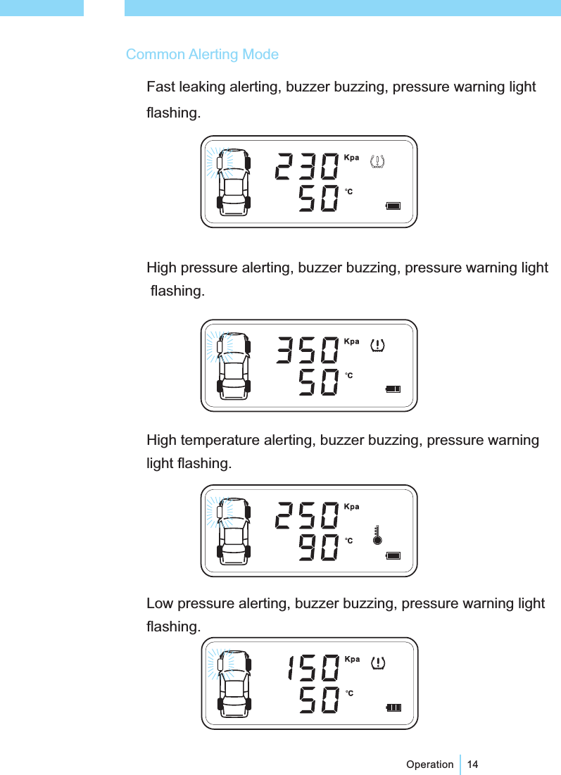
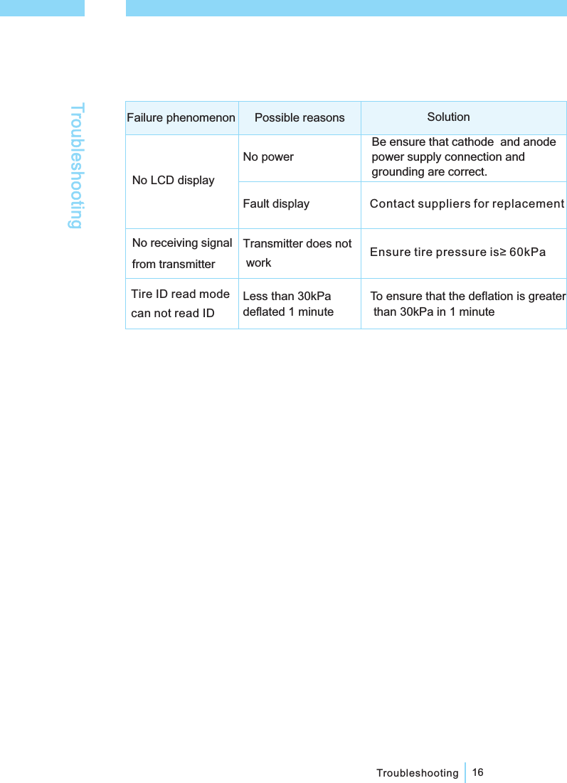
![Alerting default limitsHigh temperature alerting ≥℃80Low pressure alerting ≤190kPaHigh pressure alerting ≥330kPa15Transmitter failure alerting, buzzer buzzingLow voltage alerting, buzzer buzzingNo signal alerting, buzzer buzzingOperation*[Notice] If the alerting state displays, please solve the problem in time, which could save transmitterpower consumption.In alerting state, press any button to stop alerting sound.①②](https://usermanual.wiki/HUIZHOU-FORYOU-GENERAL-ELECTRONICS/TPMAI1DIC1-R/User-Guide-1122394-Page-20.png)