HUIZHOU GAOSHENGDA TECHNOLOGY WF75RL1510C WIFI Module User Manual WF75RL1510C 2 1 160106
Hui Zhou Gaoshengda Technology Co.,LTD WIFI Module WF75RL1510C 2 1 160106
Users Manual
PRODUCT SPECIFICATION Version 2.1
IEEE 802.11 b/g/n 1T1R USB Module
Model Number:WF75RL1510C
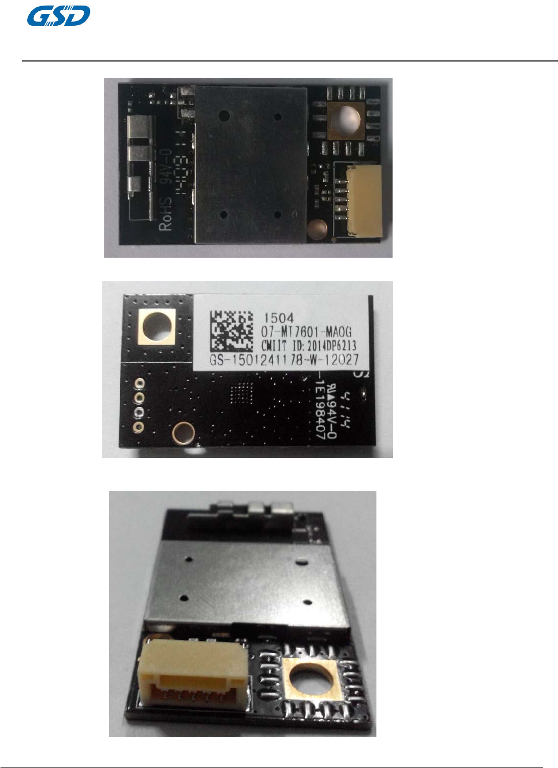
P/N: 07-MT7601-MA0G
CMIIT ID:2014DP6213
2.4G channel: 1-13
( Media Tek MT7601U )
客户认可
Custom Approval Section
Custom Name
Department
Approval Date:
拟制
DESIGN
审核
CHECK
批准
APPROVAL
高照 陈宇科 熊运自
20151210 20151210 20151210
惠 州 高 盛 达 科 技 有 限 公 司
HUIZHOU GAOSHENGDA TECHNOLOGY CO.,LTD
中国惠州仲恺高新技术开发区华宇路 75 号
HUA YU RD., NO.75, ZHONGKAI HIGH-TECH DEVELOPMENT AREA, HUIZHOU, CHINA
TEL:(0752)2096628 E-mail: gaoz@gaosd.cn
PRODUCTS SPECIFICATION
WF75RL1510C
page 2 of 12
Version 2.1
Document revision history
Rev. Date Author Reason for Changes
Version 1.0 2014-09-03 Draft
Version 1.1 2014-09-16 Adding shield cover
Version 1.2 2014-12-18 Adding P/N No.
Version 1.3 2015-01-27 Adding CMIIT ID
Update the label info
Version 1.4 2015-09-20 Edited 11b frequency range
Version 2.0 2015-12-10 PowerEN edited
Version 2.1 2016-01-06 GI edited+ FCC Statement

PRODUCTS SPECIFICATION
WF75RL1510C
page 3 of 12
Version 2.1
1. Brief Description
This document is to specify the product requirements for 802.11 b/g/n USB Module. This Module is
based on Media Tek MT7601U chipset that complied with IEEE 802.11g, IEEE 802.11b, IEEE 802.11n
standard from 2.4G-2.5GHz,and it can be used to provide up to 54Mbps for 802.11g,11Mbps for 802.11b
and 150Mbps for 802.11n to connect your wireless LAN.
With seamless roaming, fully interoperability and advanced security with WEP standard, 802.11b/g/n
USB Module offers absolute interoperability with different vendors 802.11 b, 802.11 g, 802.11n Access
Points through the wireless LAN.
2. Features
●
Compatible with IEEE 802.11b standard to provide wireless 11Mbps data rate.
●
Compatible with IEEE 802.11g standard to provide wireless 54Mbps data rate.
●
Compatible with IEEE 802.11n standard to provide wireless 150Mbps data rate.
z
Operation at 2.4G-2.5GHz frequency band to meet worldwide regulations
z
Supports WEP ,WPA ,WPA2,TKIP,AES enhanced security
z
Drivers support Windows XP 32/64, 2000, 7,Vista 32/64, linux 0S
z
High speed USB 2.0 interface
● ROHS compliant
PRODUCTS SPECIFICATION
WF75RL1510C
page 4 of 12
Version 2.1
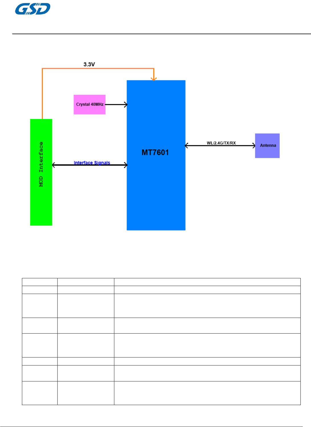
3. Application Diagrams
3.1
Functional Block Diagram
3.2 General Requirements
3.2.1 IEEE 802.11b Section
Feature
Detailed Description
3.2.1.1 Standard ● IEEE 802.11b
3.2.1.2 Radio and
Modulation
Schemes
● DQPSK , DBPSK , DSSS , and CCK
3.2.1.3 Operating
Fre
q
uenc
y
● 2400 ~ 2483.5MHz ISM band
3.2.1.4 Channel Numbers
● 11 channels for United States
● 13 channels for Europe Countries
● 14 channels for Ja
p
an
3.2.1.5 Data Rate ● 11,5.5,2,and 1Mb
p
s
3.2.1.6 Media Access
Protocol ● CSMA/CA with ACK
3.2.1.7 Transmitter Output
Power at Antenna
Connecto
r
● Typical RF Output Power at each RF chain,Data Rate and at room
Temp. 25degree C
● 17dB
m
(±2dB
)
at 1,2,5.5,11Mb
p
s
PRODUCTS SPECIFICATION
WF75RL1510C
page 5 of 12
Version 2.1
3.2.1.8 Receiver Sensitivity
at Antenna
Connector
● Typical Sensitivity at Which Frame(1000-byte PDUs)Error Rate=8%
● -76 dBm at 2Mbps
● -76 dBm for 11Mbps
3.2.2 IEEE 802.11g Section
Feature
Detailed Description
3.2.2.1 Standard ● IEEE 802.11
g
3.2.2.2 Radio and
Modulation T
yp
e ● QPSK , BPSK , 16QAM ,64QAM with OFDM
3.2.2.3 Operating
Fre
q
uenc
y
● 2400 ~ 2483.5MHz ISM band
3.2.2.4 Channel Numbers
● 11 channels for United States
● 13 channels for Europe Countries
● 13 channels for Ja
p
an
3.2.2.5 Data Rate ● 6,9,12,18,24,36,48,54Mbps
3.2.2.6 Media Access
Protocol ● CSMA/CA with ACK
3.2.2.7
Transmitter Output
Power at Antenna
Connector
● Typical RF Output Power(tolerance±2dB) at each RF chain,
Data Rate and at roomTemp. 25degree C
● +17 dBm at 6,9Mbps
● +16 dBm at 12,18Mbps
● +15 dBm at 24,36Mbps
● +14 dBm at 48,54Mb
p
s
3.2.2.8 Receiver Sensitivity
at Antenna
Connector
● Typical Sensitivity at each RF chain. Frame(1000-byte PDUs)Error
Rate<10% at room Temp 25 degree C
● -82 dBm at 6Mbps
● -81 dBm at 9Mbps
● -79 dBm at 12Mbps
● -77 dBm at 18Mbps
● -74 dBm at 24Mbps
● -70 dBm at 36Mbps
● -66 dBm at 48Mbps
● -65 dBm at 54Mbps
3.2.3 IEEE 802.11n Section
Feature
Detailed Description
3.2.3.1 Standard ● IEEE 802.11n
3.2.3.2 Radio and
Modulation T
yp
e ● BPSK , QPSK , 16QAM ,64QAM with OFDM
3.2.3.3 Operating
Fre
q
uenc
y
● 2400 ~ 2483.5MHz
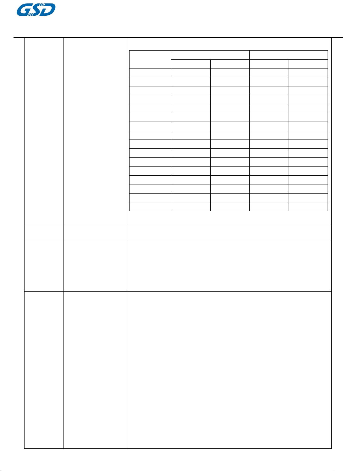
3.2.3.4 Data Rate
(
Mb
p
s
)
PRODUCTS SPECIFICATION
WF75RL1510C
page 6 of 12
Version 2.1
MCS GI=800ns GI=400ns
20MHz 40MH 20MHz 40MHz
0 6.5 13.5 7.2 15
1 13 27 14.4 30
2 19.5 40.5 21.7 45
3 26 54 28.9 60
4 39 81 43.3 90
5 52 108 57.8 120
6 58.5 121.5 65.0 135
7 65 135 72.2 150
8 13 27 14.444 30
9 26 54 28.889 60
10 39 81 43.333 90
11 52 108 57.778 120
12 78 162 86.667 180
13 104 216 115.556 240
14 117 243 130.000 170
15 130 270 144.444 300
3.2.3.5 Media Access
Protocol ● CSMA/CA with ACK
3.2.3.6 Transmitter Output
Power at Antenna
Connector
● Typical RF Output Power(tolerance±2dB) at each RF chain,Data Rate
and at roomTemp. 25degree C
HT-20
● 14±2dBm at MCS0~15
HT-40
● 14±2dBm at MCS0~15
3.2.3.7 Receiver Sensitivity
at Antenna
Connector
● Typical Sensitivity at Which Frame (1000-byte PDUs) Error Rate=10%
and at roomTemp. 25degree C
HT-20
● -82dBm at MCS0/8
● -79dBm at MCS1/9
● -77dBm at MCS2/10
● -74dBm at MCS3/11
● -70dBm at MCS4/12
● -66dBm at MCS5/13
● -65dBm at MCS6/14
● -64dBm at MCS7/15
HT-40
● -79dBm at MCS0/8
● -76dBm at MCS1/9
● -74dBm at MCS2/10
● -71dBm at MCS3/11
● -67dBm at MCS4/12
● -63dBm at MCS5/13
● -62dBm at MCS6/14
● -61dBm at MCS7/15

PRODUCTS SPECIFICATION
WF75RL1510C
page 7 of 12
Version 2.1
4. Electrical and Thermal Characteristics
4.1
Temperature
Limit
Ratings
Parameter
Minimum
Maximum
Units
Storage
Temperature
-40
+80
°
C
Ambient
Operating
Temperature
0
60
°
C
Junction
Temperature
0
125
°
C
4.2
General Section
4.3 Software Requirements
Driver
Windows XP 32/64, 2000, 7,Vista 32/64, linux 0S
Security WEP ,WPA ,WPA2,TKIP,AES
4.3.1 Information
Feature Detailed Description
4.3.1.1 General
Information ● General Information shows the name of Wireless Adapter,Adapter
MAC Address,Regulatory Domain,Firmware Version,and Utility
Version.
4.3.1.2 Current Link
Information
● Current Link Information shows the C
4.3.1.3 Site survey ● To search the neighboring access points and display the information
of all access points.
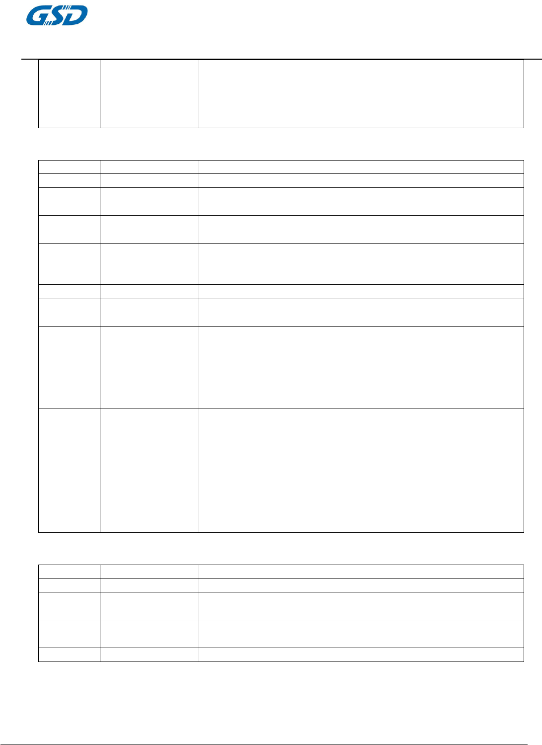
Feature Detailed Description
5.2.1 Antenna Type ● Integrated antenna
5.2.2 Operating Voltage ● 5.0V±10%
5.2.3 Current
Consumption
● 230mA at continuous transmit mode
● 190mA at receive mode w/o receiving packet
5.2.4 USB ● High Speed USB2.0 Interface
PRODUCTS SPECIFICATION
WF75RL1510C
page 8 of 12
Version 2.1
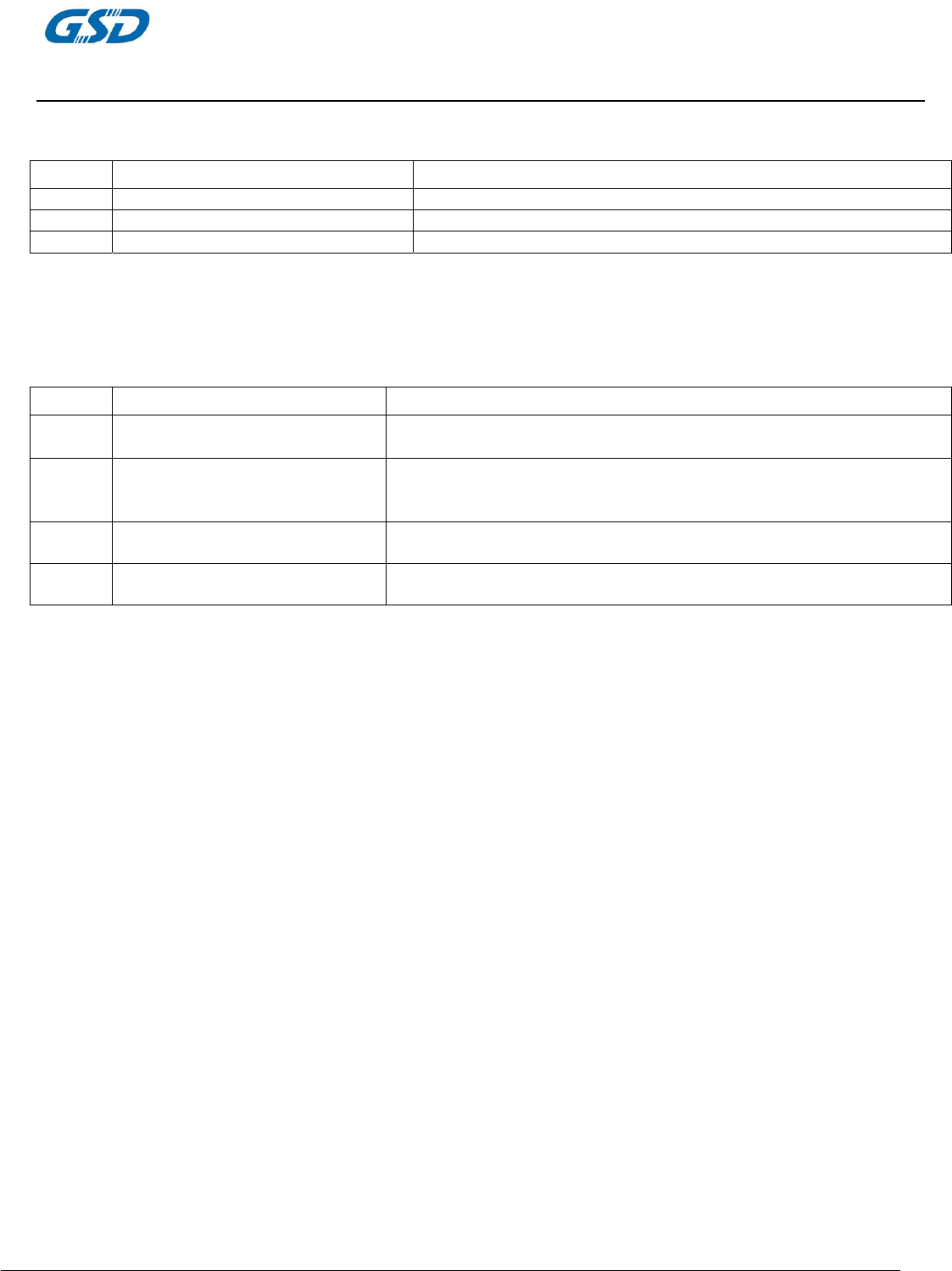
4.3.2 Mechanical Requirements
Feature Detailed Description
4.3.2.1 Length ● 36mm(PCB)
4.3.2.2 Width ● 22mm(PCB)
4.3.2.3 Height ● 1.0mm(PCB)
4.3.3 Environmental Requirements
Feature Detailed Description
4.3.3.1 Operating Temperature Conditions ● The product is capable of continuous reliable operation when operating
in ambient temperature of 0
°
C to +
45
°
C .
4.3.3.2 Non-Operating
Temperature Conditions
● Neither subassemblies is damaged nor the operational performance is
degraded when restored to the operating temperature after exposing to
storage temperature in the range of -20
°
C to +
75
°
C .
4.3.3.3 Operating Humidity conditions ● The product is capable of continuous reliable operation when subjected
to relative humidity in the range of 10% and 90% non-condensing.
4.3.3.4 Non-Operating
Humidity Conditions
● The product is not damaged nor the performance is degraded after
exposure to relative humidity ranging from 5% to 95% non-condensing
PRODUCTS SPECIFICATION
WF75RL1510C
page 9 of 12
Version 2.1
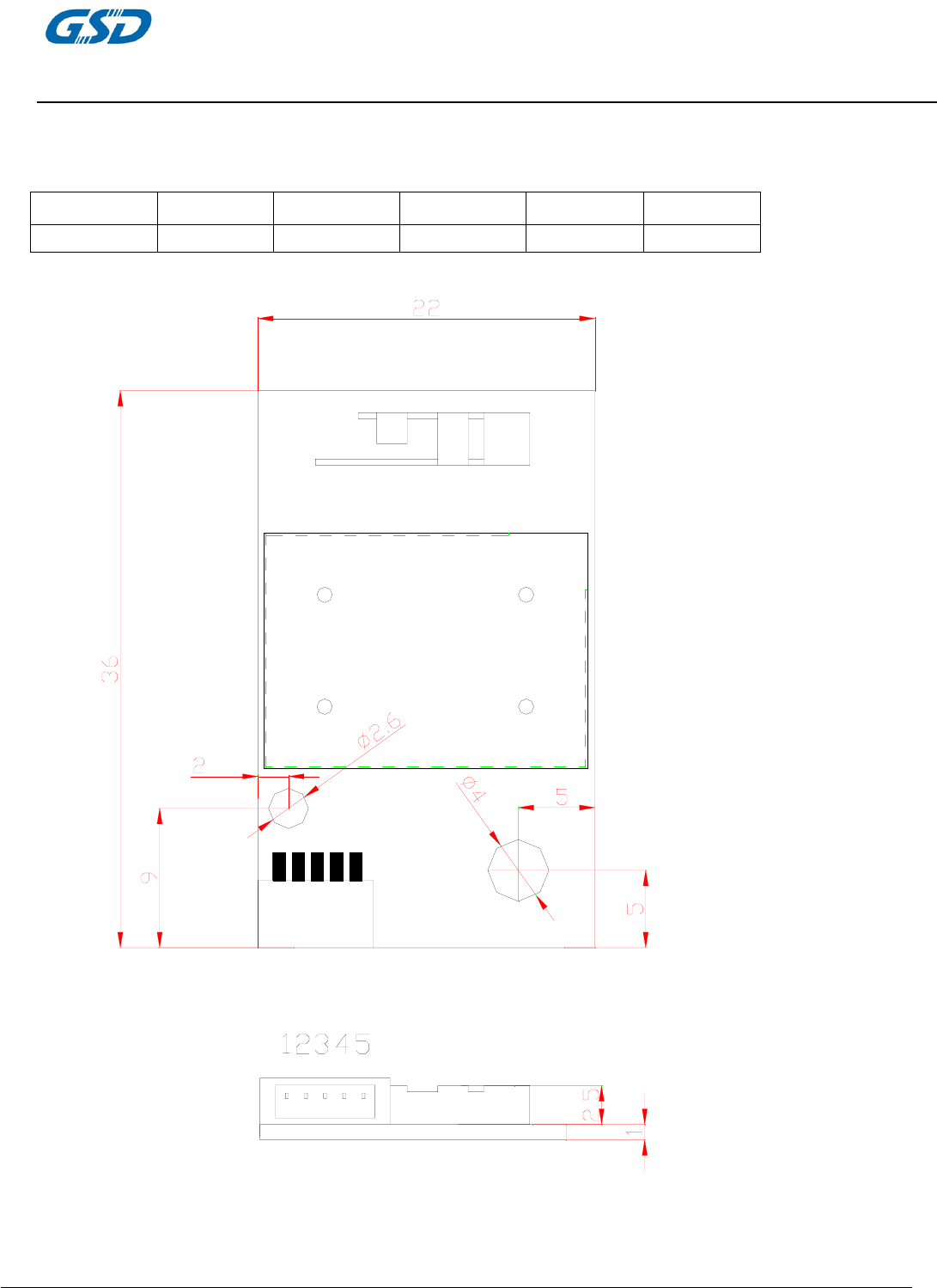
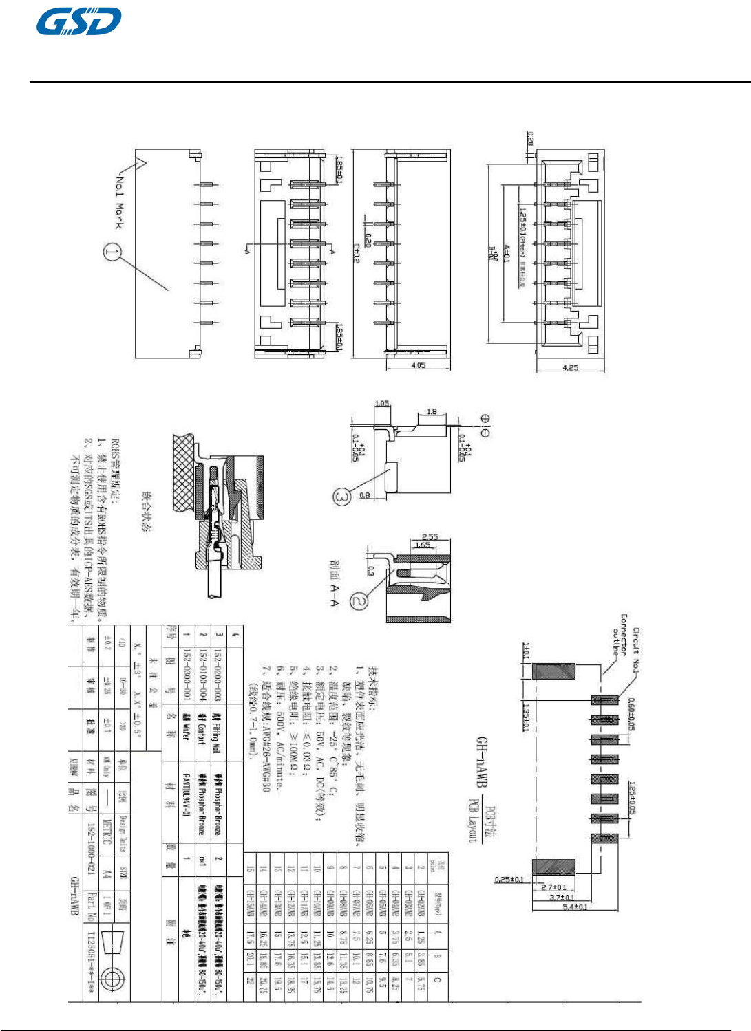
5 Connector Definition
1,5-Pin 1.25mm connector(Horizontal Type)
Pin 1 2 3 4 5
Definition Power-en GND D+ D- Vcc
`
*TLERANCES ARE +/-0.5mm UNLESS OTHERWISE SPECIFIED
*UNIT:mm
PRODUCTS SPECIFICATION
WF75RL1510C
page 10 of 12
Version 2.1
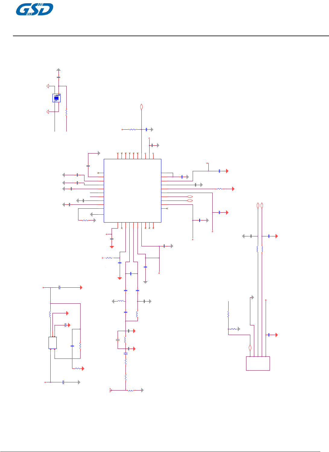
Appendix 1 : Schematic
RST_N
R3
18K
GND
3.3VD
1.2VD
R3
0R
3.3VD
C10
0.1uF
12
GND
UDM
UDP
C27
1.0pF
12
GND
C36
1.0pF
12
GND
3.3VD
3.3VD
RST_N
LV7 18nH
12
GND
GND
LV8 18nH
1 2
GND U+
U-
5VD
3.3VD
3
4
5
Y1
1
2
VRES
R5
8.2K
12
GND
C1
0.1uF
1 2
C13
1uF
12
R8
24K
12
GND
GND
GND
C41
5.6pF
1 2
C42
5.6pF
1 2
3.3VD
C8
1uF
12
XTAL_V12A
C31
1uF
1 2
GND
C7
0.1uF
12
UDP
UDM
GND
GND
3.3VD
5VD
GND
1.2VD
3.3VD
C26
1uF
12
GND
C24
0.1uF
12
GND
C6
2.2uF
12
Power-EN
GND
C30
0.1uF
1 2
PMU_OUT
GND
GND
GND
C12
0.1uF
12
GND
3.3VD
MT7601-QFN40-5X5
IC1
RF0_IN
2
RF0_VX_LDO
1
RF0_PA2_V33A
3
RF0_OUTP
4
RF0_OUTN
5
RF0_PA1_V33A
6
VCCIO
7
EE_MISO
8
EE_MOSI
9
EE_CLK
10
EEFL_CS
11
VDD
12
PADP
13
PADM
14
VDDA
15
VRES
16
VOUT_1P2
17
LDO_V15A
18
DCDC_V33A
19
FB
20
COMP 21
DCDC_V33D 22
PHASE 23
LDO_RST_N 24
WL_GPIO6 25
WL_GPIO5 26
WL_GPIO4 27
WL_GPIO3 28
WL_GPIO2 29
WL_GPIO1 30
WL_GPIO0 31
VDD 32
VCCIO 33
AVDD12 34
ADC_VX_LDO 35
XTAL_XO 36
XTAL_XI 37
XTAL_V12A 38
PLL_VX_LDO 39
BG_EXTR 40
GND 41
PMU_OUT
3.3VD
C28
0.1uF
12
RF0_PA_OUTP
RF0_PA_OUTN
R9 0 ohm
12
GND
1.2VD
5VD
GND
FB
Q1
G5728
FB
5GND 2
EN 1
VIN
4LX/SW 35VD
Vo = 0.6 * ( 1 + R3/R4) = 0.6 * ( 1+82K/18K ) = 3.3V
Power-EN
GND
GND
3.3VD
3.3VD
C11
1uF
GND
C3
10uF
C43
100pF
1 2 GND
R4
82K
LV1 4.7uH
1 2
3.3VD
XI
GND
XO
C34
47pF
1 2
2.5x3.2
U5
XTAL/40MHz
1
2
4
3
GND GND
ANTENNA
GND
C38
10pF
LV5
1nH
1 2
LV6
2.2nH
1 2
C33
0.5pF
R2
100K
1 2
R1
150K
1 2
GND
GND
XI
XO_0
RF0_PA_OUTN
RFOUT_G0
C21
1.2pF
12
GND
LV3
2.7nH 12 C19
10pF
12
LV4
2.7nH
1 2
C17
10pF
12
C20
1.2pF
12
GND
C18
1.0pF
1 2
RF0_PA_OUTP
5VD
XO
C29
0.1uF
12
C4
0.1uF
GND
C32
0.1uF
1 2
C5
1uF
12
C14
0.1uF
12
GND
GND
GND
R7
150K
12
3.3VD
C16
0.1uF
12
3.3VD
R11
0
1 2 R10
0
1 2
GND
PA0_OUT+
PA0_OUT-
1.2VD
C25
1uF
12
GND
PRODUCTS SPECIFICATION
WF75RL1510C
page 11 of 12
Version 2.1
Appendix 2 : SMT connector
PRODUCTS SPECIFICATION
WF75RL1510C
page 12 of 12
Version 2.1
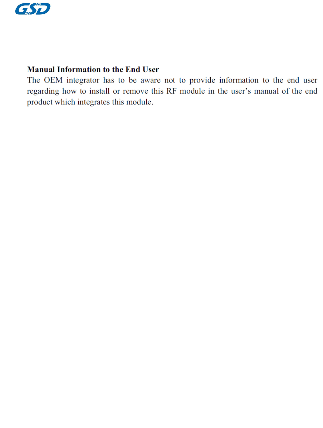
Appendix 3 : Top & Bottom vertical view
Connector view:

PRODUCTS SPECIFICATION
WF75RL1510C
page 13 of 12
Version 2.1
FCC Statement
This equipment has been tested and found to comply with the limits for a Class B digital
device, pursuant to part 15 of the FCC rules. These limits are designed to provide reasonable
protection against harmful interference in a residential installation. This equipment
generates, uses and can radiate radio frequency energy and, if not installed and used in
accordance with the instructions, may cause harmful interference to radio communications.
However, there is no guarantee that interference will not occur in a particular installation.
If this equipment does cause harmful interference
to radio or television reception, which can be determined by turning the equipment off and
on, the user is encouraged to try to correct the interference by one or more of the following
measures:
-Reorient or relocate the receiving antenna.
-Increase the separation between the equipment and receiver.
-Connect the equipment into an outlet on a circuit different from that to which the receiver
is connected.
-Consult the dealer or an experienced radio/TV technician for help.
To assure continued compliance, any changes or modifications not expressly approved by the
party responsible for compliance could void the user’s authority to operate this equipment.
FCC Radiation Exposure Statement
This equipment complies with FCC RF radiation exposure limits set forth for an uncontrolled
environment.
This equipment complies with Part 15 of the FCC Rules. Operation is subject to the following
two conditions:
(1) This device may not cause harmful interference, and
(2) This device must accept any interference received, including interference that may cause
undesired operation.
The devices must be installed and used in strict accordance with the manufacturer’s
instructions as described in the user documentation that comes with the product. Modular
could be only used in mobile or fix device, and could not be used in any portable device.
The module must be installed in TV set.
In the event that these conditions can not be met (for example certain laptop configurations
or co-location with another transmitter), then the FCC authorization is no longer considered
valid and the FCC ID can not be used on the final product. In these circumstances, the OEM
integrator will be responsible for re-evaluating the end product (including the transmitter)
and obtaining a separate FCC authorization.
Caution!
The manufacturer is not responsible for any radio or TV interference caused by unauthorized
modifications to this equipment. Such modifications could void the user authority to operate
the equipment.
Regulation information
(1) This device and its antenna(s) must not be co-located or operating in conjunction with any other
PRODUCTS SPECIFICATION
WF75RL1510C
page 14 of 12
Version 2.1
antenna or transmitter.
(2) This compliance to FCC radiation exposure limits for an uncontrolled environment, and minimum of
20cm separation between antenna and body.
⑶
⑷ The end product must carry a label stating “Contains TX FCC ID: 2AC23-WF75RL1510C ”.