HUIZHOU GAOSHENGDA TECHNOLOGY WT39M2011 WIFI+BT Module User Manual WT39M2011 Usermanual
Hui Zhou Gaoshengda Technology Co.,LTD WIFI+BT Module WT39M2011 Usermanual
UserManual.wiki
>
HUIZHOU GAOSHENGDA TECHNOLOGY
>
WT39M2011 User Manual
User Manual
Navigation menu
Upload a User Manual
Namespaces
Wiki Guide
HTML
PDF
Info
Views
User Manual
Discussion / Help
Navigation


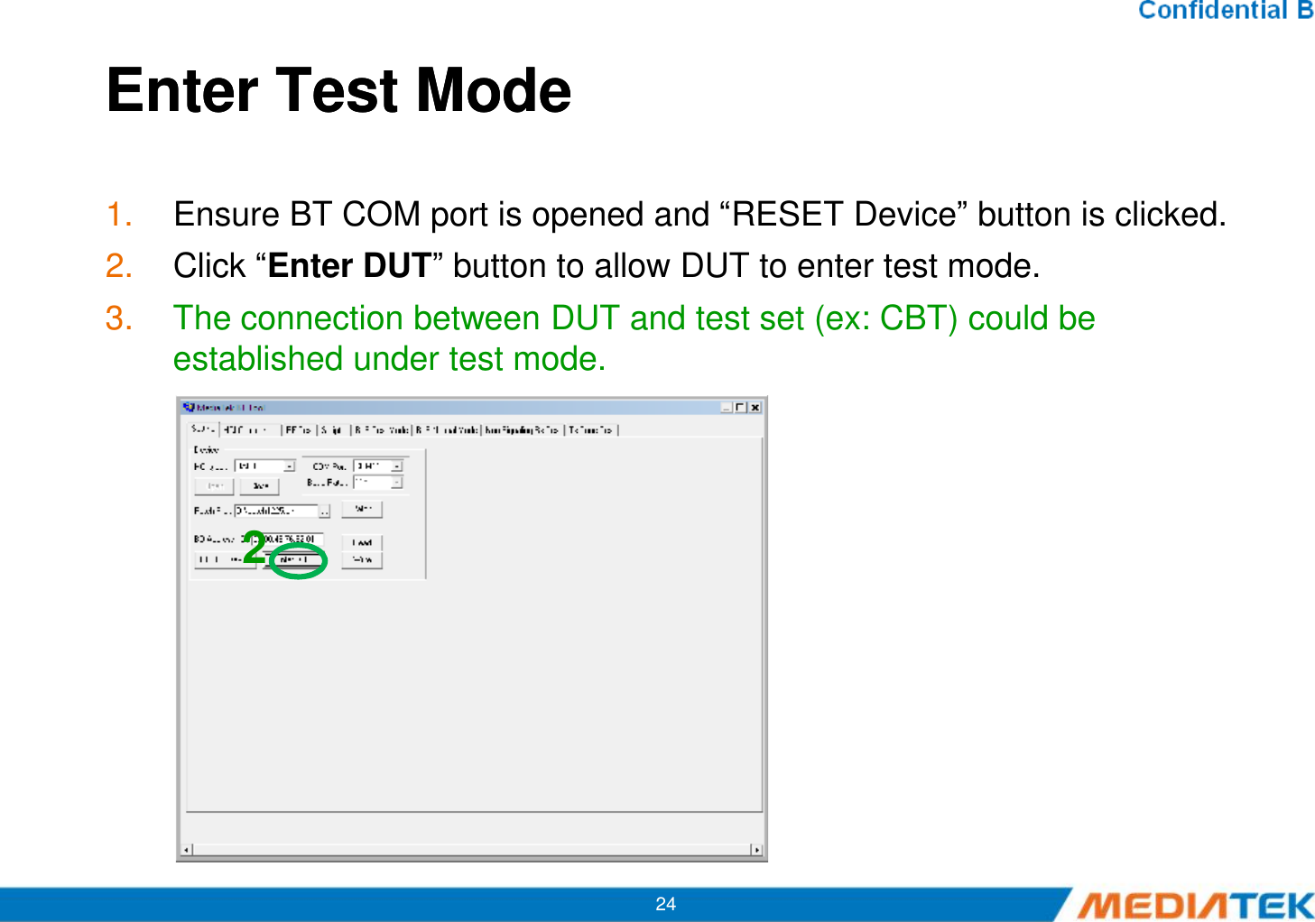
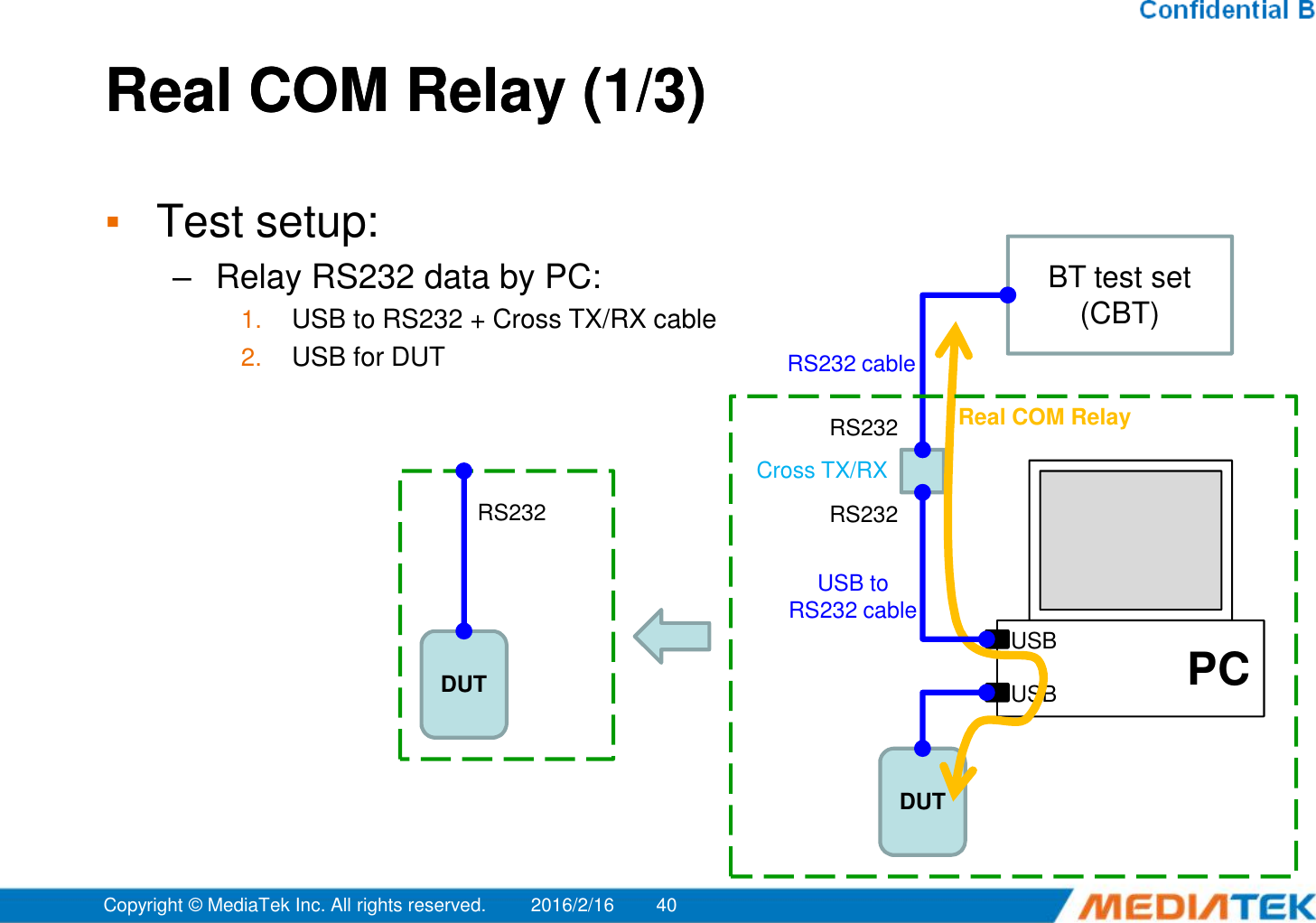
![HoppingHopping▪Select “Frequency Hopping”, and then see if TX signal is present on spectrum analyzer correctly. A Offset 1 dBLVLRef 10 dBm Att 40 dB 1 PKMAXH*RBW 1 MHzVBW 3 MHzSWT 2.5 ms-100101Marker 1 [T1 ] 3.72 dBm 2.402000000 GHz2Marker 2 [T1 ] 4.69 dBm 2.480000000 GHz29Frequency HoppingCenter2.45 GHz Span100 MHz10 MHz/3DB-90-80-70-60-50-40-30-20](https://usermanual.wiki/HUIZHOU-GAOSHENGDA-TECHNOLOGY/WT39M2011/User-Guide-2917859-Page-37.png)
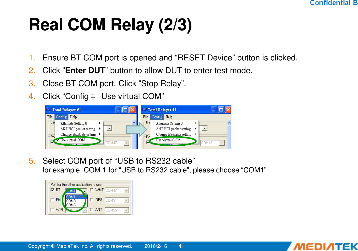
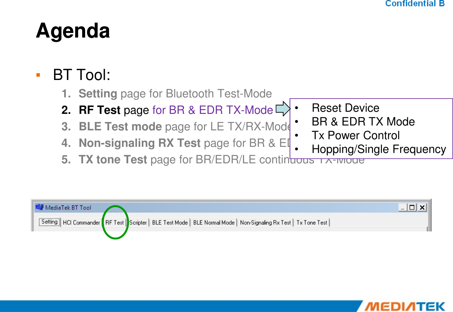
![Single FrequencySingle Frequency A RBW 3 MHzVBW 10 MHzSWT 2.5 msOffset 1 dBRef 10 dBmAtt 40 dB0101Marker 1 [T1 ] 3.98 dBm 2.402000000 GHzSelect “Single Frequency”, and then change the channel number (00~78) ,TX signal is present on spectrum analyzer correspondingly. A RBW 3 MHzVBW 10 MHzSWT 2.5 msOffset 1 dBRef 10 dBmAtt 40 dB0101Marker 1 [T1 ] 4.35 dBm 2.441000000 GHz A RBW 3 MHzVBW 10 MHzSWT 2.5 msOffset 1 dBRef 10 dBmAtt 40 dB0101Marker 1 [T1 ] 4.87 dBm 2.480000000 GHz A 3DBLVLCenter2.45 GHz Span100 MHz10 MHz/ 1 PKMAXH-90-80-70-60-50-40-30-20-1000ch 39ch 78ch A 3DBLVLCenter2.45 GHz Span100 MHz10 MHz/ 1 PKMAXH-90-80-70-60-50-40-30-20-100 A 3DBLVLCenter2.45 GHz Span100 MHz10 MHz/ 1 PKMAXH-90-80-70-60-50-40-30-20-100](https://usermanual.wiki/HUIZHOU-GAOSHENGDA-TECHNOLOGY/WT39M2011/User-Guide-2917859-Page-38.png)
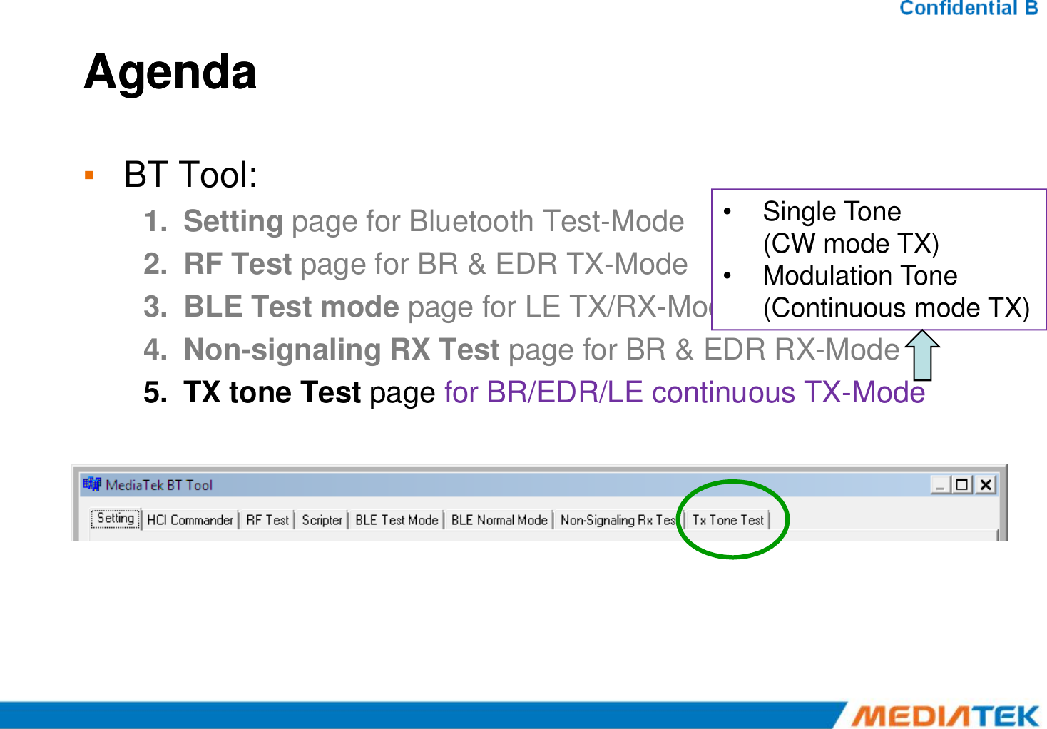
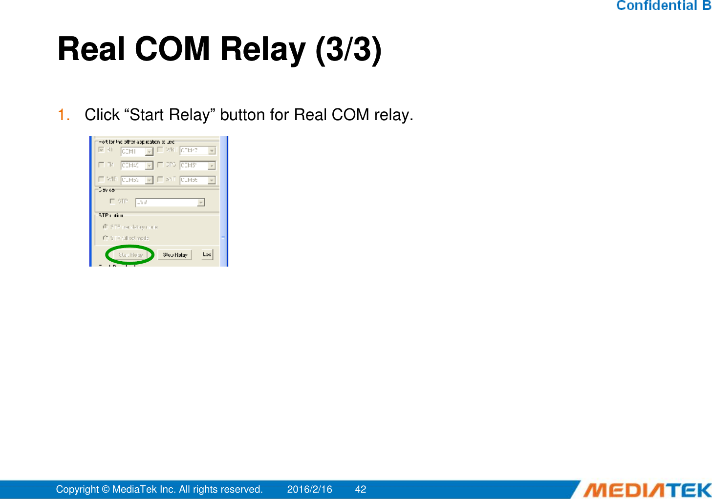
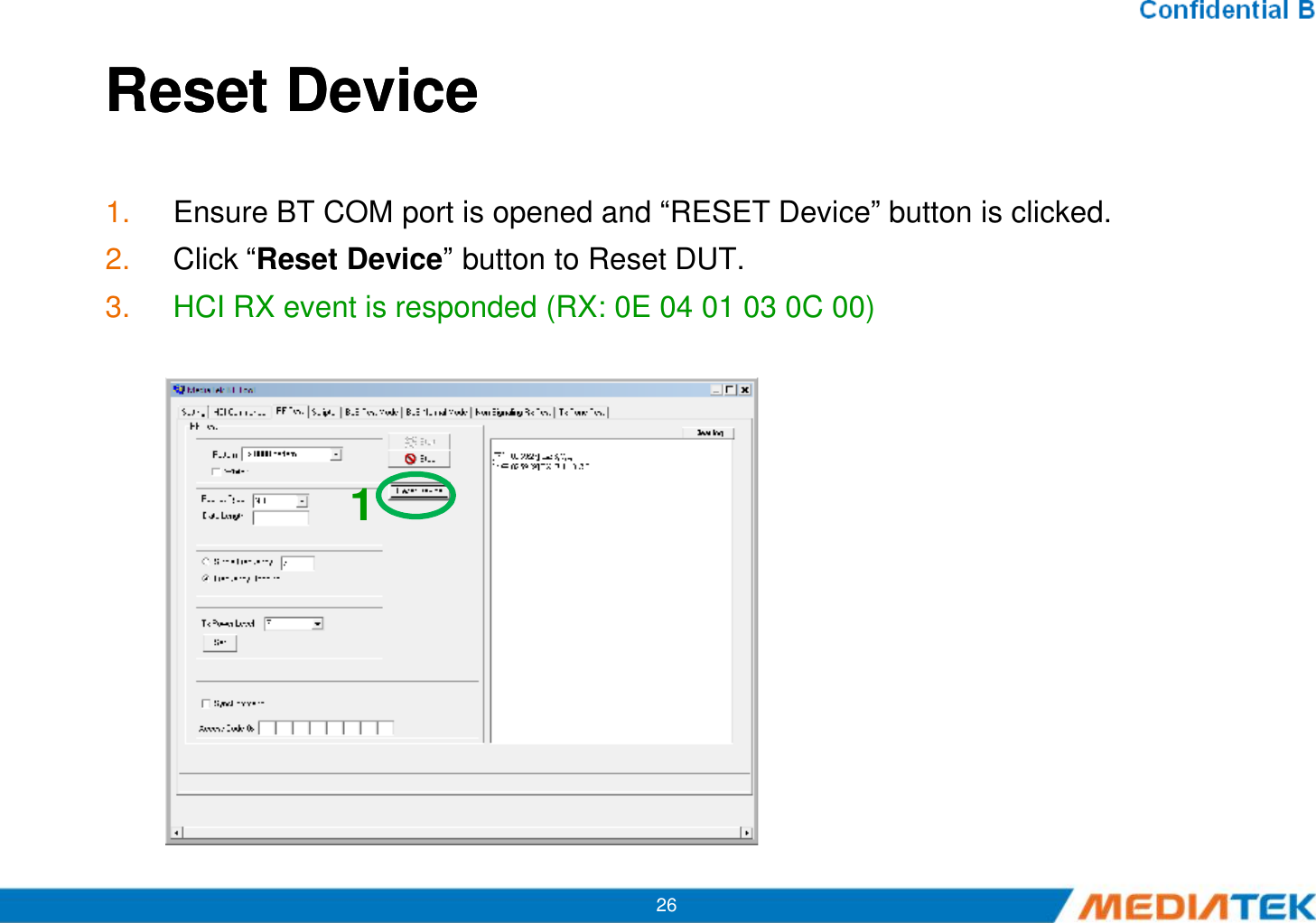
![Single Tone Single Tone –– CW tone TX (No modulated signal)1. Ensure BT COM port is opened and “RESET Device” button is clicked.2. Select Tone Type (ex: Single_Tone_DC), and then change the channel number (00~78)3. Click “Enter Test” button. TX signal is present on spectrum analyzer correspondingly.4. Click “HCI Reset” button to end test.1Ref 20 dBmAtt 30 dB**RBW 10 kHzVBW 30 kHzSWT 20 ms20Marker 1 [T1 ] 8.81 dBm 2.401992000 GHz122 APCLRWR A 200 kHz/Center2.402 GHz Span2 MHz1 PKMAXH-80-70-60-50-40-30-20-10010201](https://usermanual.wiki/HUIZHOU-GAOSHENGDA-TECHNOLOGY/WT39M2011/User-Guide-2917859-Page-45.png)
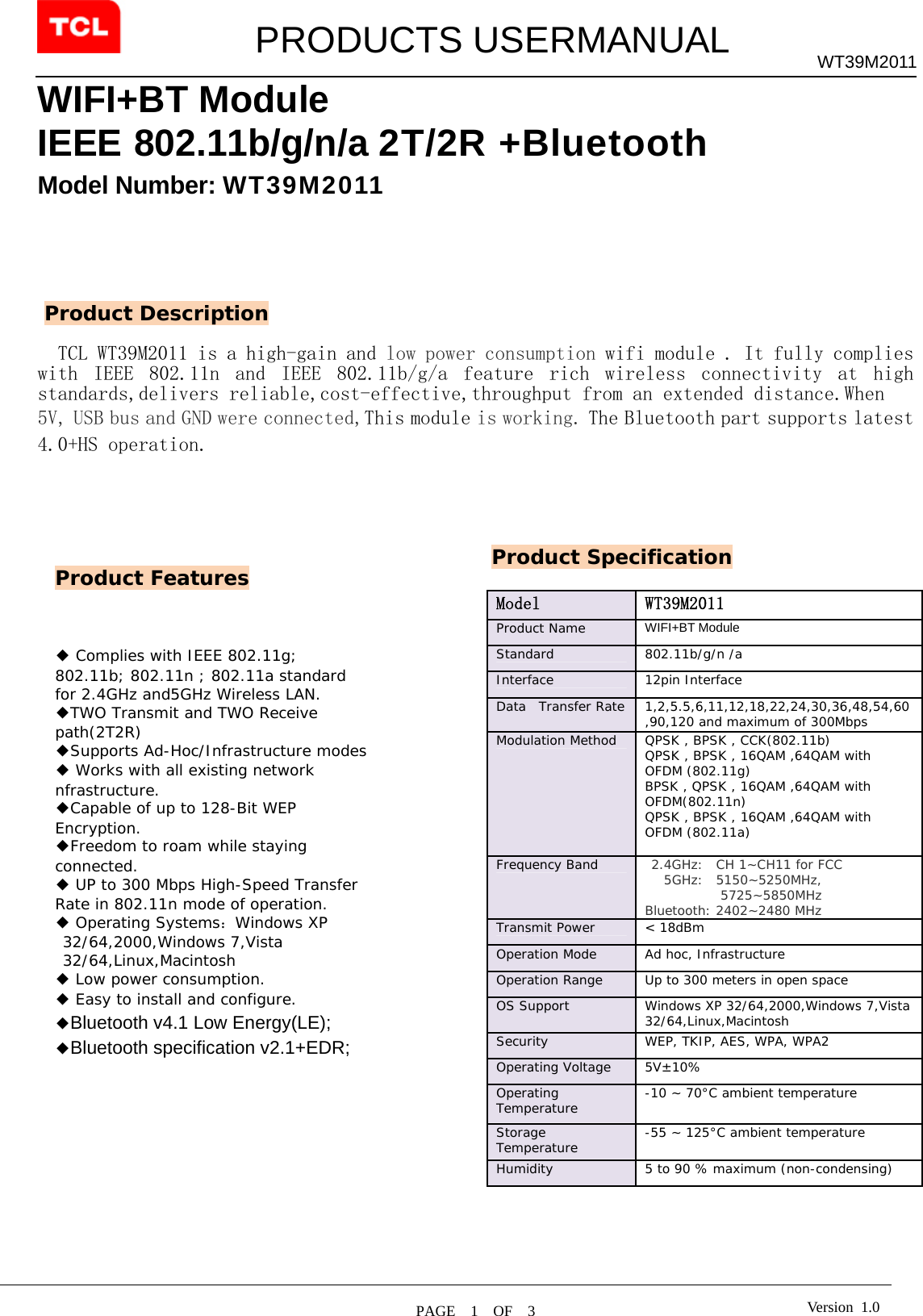
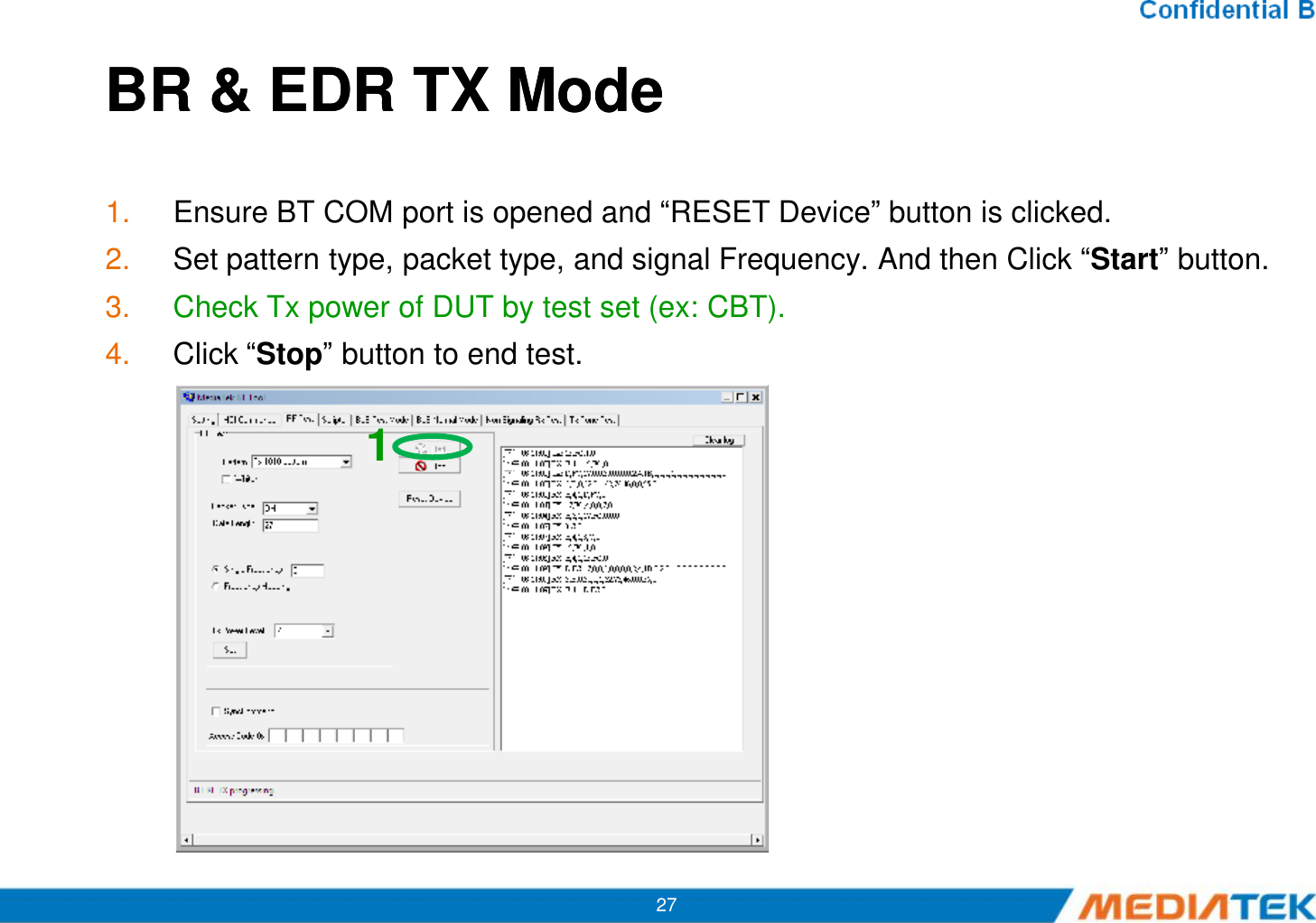
![Modulation Tone Modulation Tone –Continuous mode TX1. Ensure BT COM port is opened and “RESET Device” button is clicked.2. Select “Modulation_Tone”, and then change the channel number (00~78).Choose mode (BT-GFSK/EDR or LE) and Modulation rate (1M/2M/3M)3. Click “Enter Test” button. TX signal is present on spectrum analyzer correspondingly.4. Click “HCI Reset” button to end test.1Ref 20 dBmAtt 30 dB**RBW 10 kHzVBW 30 kHzSWT 20 ms20Marker 1 [T1 ] 8.81 dBm 2.401992000 GHz122 APCLRWR A 200 kHz/Center2.402 GHz Span2 MHz1 PKMAXH-80-70-60-50-40-30-20-10010201](https://usermanual.wiki/HUIZHOU-GAOSHENGDA-TECHNOLOGY/WT39M2011/User-Guide-2917859-Page-46.png)