HUIZHOU GAOSHENGDA TECHNOLOGY WT4XR1210 WIFI+BT module User Manual PowerPoint
Hui Zhou Gaoshengda Technology Co.,LTD WIFI+BT module PowerPoint
UserManual.wiki
>
HUIZHOU GAOSHENGDA TECHNOLOGY
>
WT4XR1210 User Manual
User manual 2
Navigation menu
Upload a User Manual
Namespaces
Wiki Guide
HTML
PDF
Info
Views
User Manual
Discussion / Help
Navigation


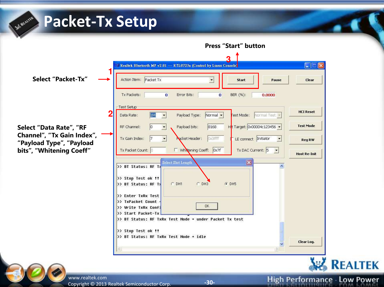

![-43- Copyright © 2013 Realtek Semiconductor Corp. www.realtek.com Tx Test Setup: Select “Packet-Tx” 1 2 3 Select “Data Rate”, “RF Channel”, “Tx Gain Index”, “Payload Type”, “Payload bytes” “Date Rate” = [LE] Press “Start” to start Tx and BT tester can start measurement. 4 Press “Stop” to stop Tx.](https://usermanual.wiki/HUIZHOU-GAOSHENGDA-TECHNOLOGY/WT4XR1210/User-Guide-2891058-Page-44.png)
![-44- Copyright © 2013 Realtek Semiconductor Corp. www.realtek.com Rx Test Setup: Select “Packet-Rx” 1 2 3 Select “Data Rate”, “RF Channel”, “Payload Type”, “Payload bytes” “Date Rate” = [LE] Press “Start” to start Rx and BT tester can start sending packet. 4 Press “Stop” to stop Rx.](https://usermanual.wiki/HUIZHOU-GAOSHENGDA-TECHNOLOGY/WT4XR1210/User-Guide-2891058-Page-45.png)
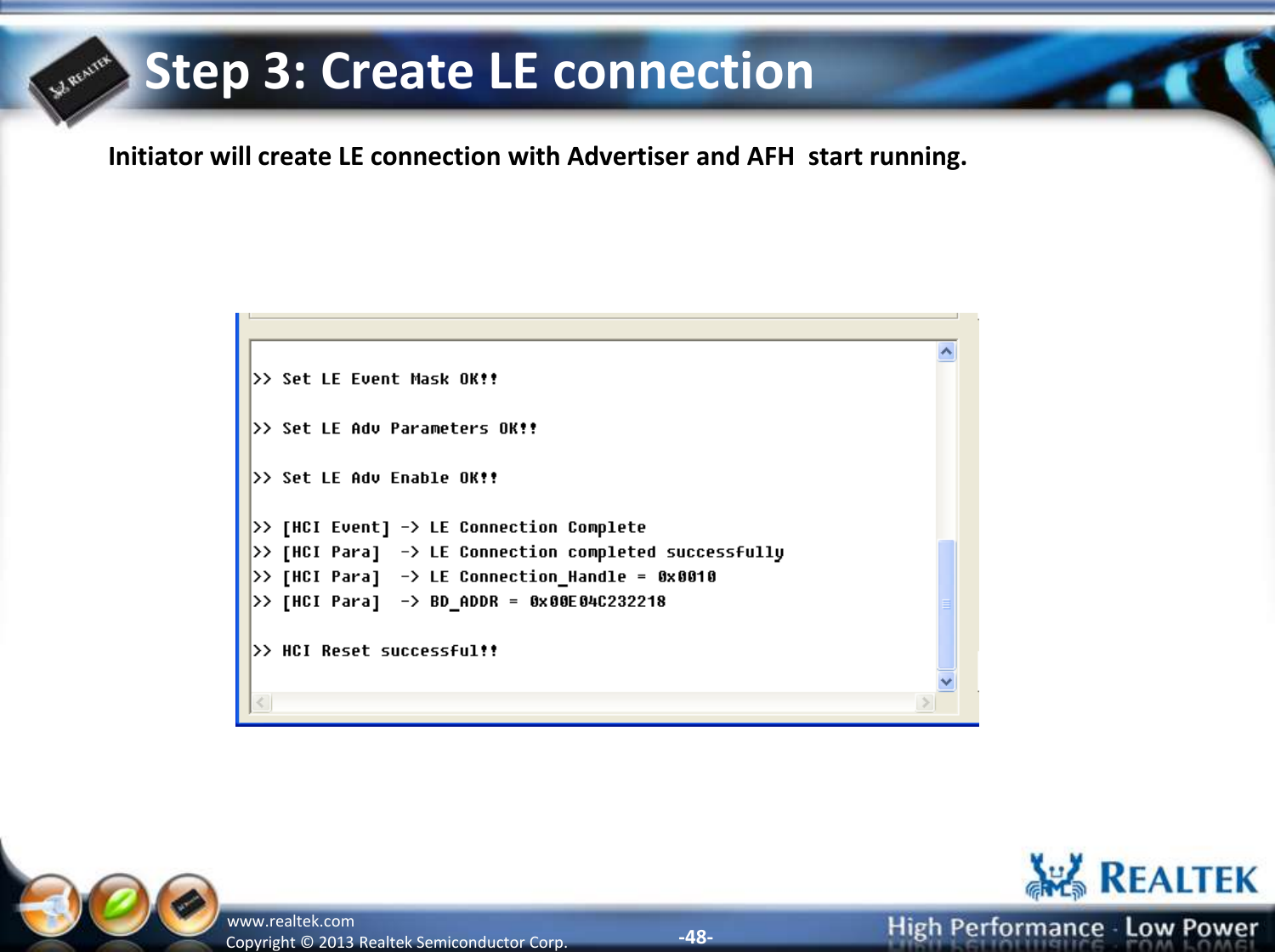
![-46- Copyright © 2013 Realtek Semiconductor Corp. www.realtek.com Step 1: Create LE connection (Initiator) 1. Checked [LE connect] and select “Initiator”. 2. Key in the Target BD Address in the [Hit Target] and press “Enter” key 3. In the Action Items, select “Page + Create ACL connection” 4. press [Start] button 1. 3. 4. 2.](https://usermanual.wiki/HUIZHOU-GAOSHENGDA-TECHNOLOGY/WT4XR1210/User-Guide-2891058-Page-47.png)
![-47- Copyright © 2013 Realtek Semiconductor Corp. www.realtek.com Step 2: Create LE connection (Advertiser) 1. Checked [LE connect] and select “Advertiser”. 2. In the Action Items, select “Page + Create ACL connection” 3. press [Start] button 1. 2. 3.](https://usermanual.wiki/HUIZHOU-GAOSHENGDA-TECHNOLOGY/WT4XR1210/User-Guide-2891058-Page-48.png)