HUIZHOU GAOSHENGDA TECHNOLOGY WT4XR1210 WIFI+BT module User Manual PowerPoint
Hui Zhou Gaoshengda Technology Co.,LTD WIFI+BT module PowerPoint
User manual 2

-1-
Copyright © 2013 Realtek Semiconductor Corp.
www.realtek.com
Realtek Bluetooth
MP UI User Guide
A. Electrical Characteristics
Working Frequency 2.4GHz~2.5GHz
4.9GHz~5.85GHz
S.W.R. 2.4GHz~2.5GHz <2.0
4.9GHz~5.85GHz <2.0
Antenna Gain Main port:2dBi
Efficiency 2.4GHz~2.5GHz >70%
4.9GHz~5.85GHz >75%
Impedance 50 Ohm
Polarization / Azimuth Linear / Omni-directional
B. Mechanical Dimension
Cable Length Of Main Ant L:340mm(BLACK)
Cable Length Of Aux Ant
C. Material
Stamping Metal Copper antenna
Coaxial Cable 50 Ohm / O.D.1.13mm
Mini Coaxial Connector IPEX PLUG
D. Environmental
Operation Temperature -40℃~ +85℃
Storage Temperature -40℃~ +85℃
Aux port:2dBi
Antenna Type PCB

-2-
Copyright © 2013 Realtek Semiconductor Corp.
www.realtek.com
Bluetooth MP Operation Flow
-3-
Copyright © 2013 Realtek Semiconductor Corp.
www.realtek.com
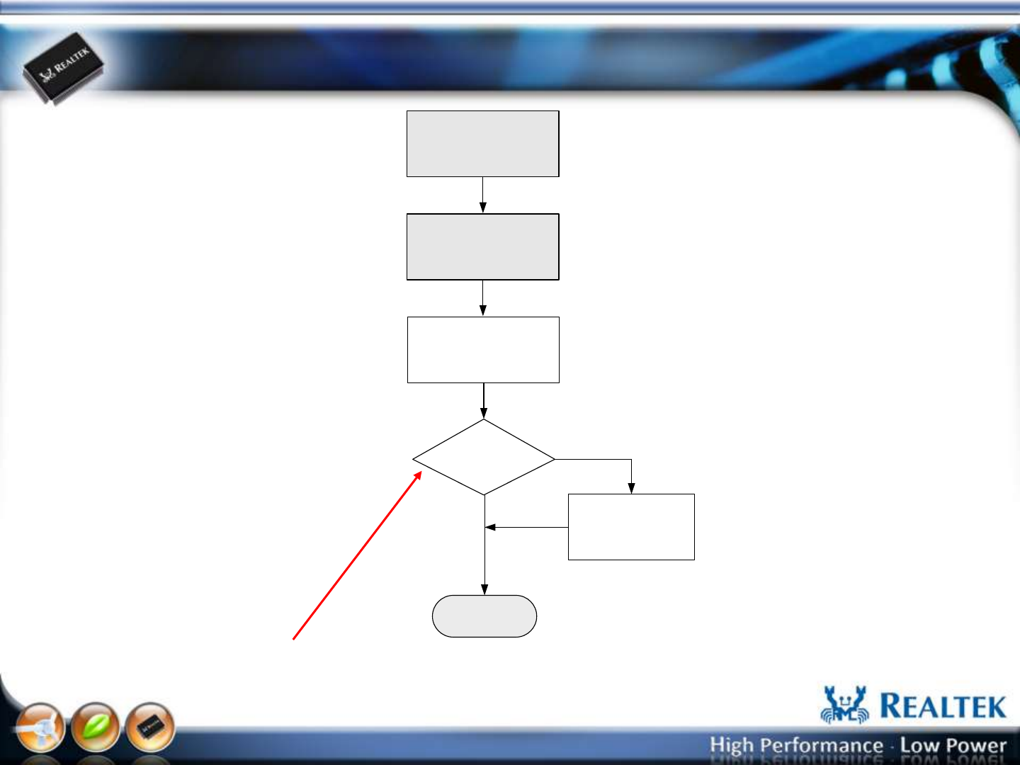
Host Interface: BT USB/UART/PCIe
Set “IsFirmwarePatchAtInit” in the HCISetup.ini, 0Skip Patch, 1Patch
The patch file is “patch.bin” (located the same directory with RTK_BT_MP.exe)
Power on DUT
Open UI & Select
Host Control Interface
Host Interface and
Parameter Initial
If BT Patch?
No
Yes
Enter MP UI
Send Patch code by
HCI vendor command
-4-
Copyright © 2013 Realtek Semiconductor Corp.
www.realtek.com
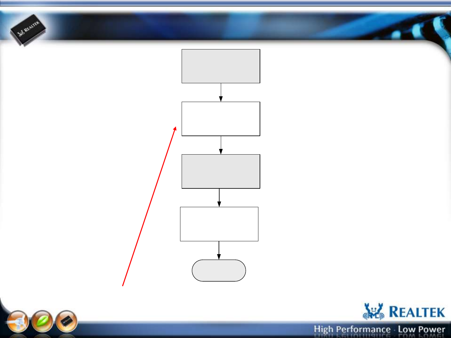
Host Interface: WiFi USB/UART/PCIe (Windows
Platform)
The WiFi driver must download BT patch while DUT power on.
Power on DUT
Host Interface and
Parameter Initial
Enter MP UI
Send Patch code by WiFi
via Mailbox
Open UI & Select
Host Control Interface
-5-
Copyright © 2013 Realtek Semiconductor Corp.
www.realtek.com
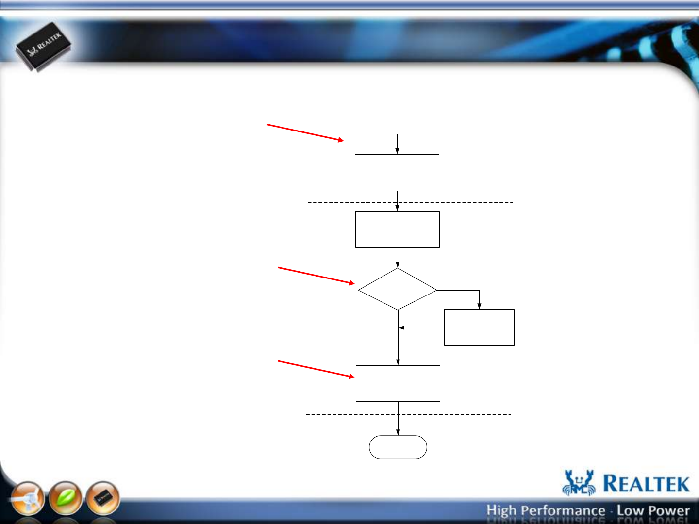
Host Interface: Linux Platform
Power on DUT
Open UI & Select
Host Control Interface
Host Interface and
Parameter Initial
If Push WiFi driver?
No
Yes
Push WiFi driver to
Platform
Enter MP UI
Inser WLAN mdule
Enable WLAN
Download BT Patch
The WiFi in the DUT UI must be turned off
after Power on. (no WLAN module exit in
the system)
“IsPushMPDriver” in the HCISetup.ini
defines: 0 skip push, 1push.
The MP driver filename is specified in the
“ADBMPDriverFilename” of the HCISetup.ini
It must place in the same directory with
RTK_BT_MP.exe.
The push destination is defined in the
“ADBMPDriverRoute” of the HCISetup.ini .
The insert WiFi module is specified by the
“ADBMPDriverRoute” + “ADBMPDriverFilename”
in the HCISetup.ini .
.

-6-
Copyright © 2013 Realtek Semiconductor Corp.
www.realtek.com
Bluetooth MP UI Initial
-7-
Copyright © 2013 Realtek Semiconductor Corp.
www.realtek.com
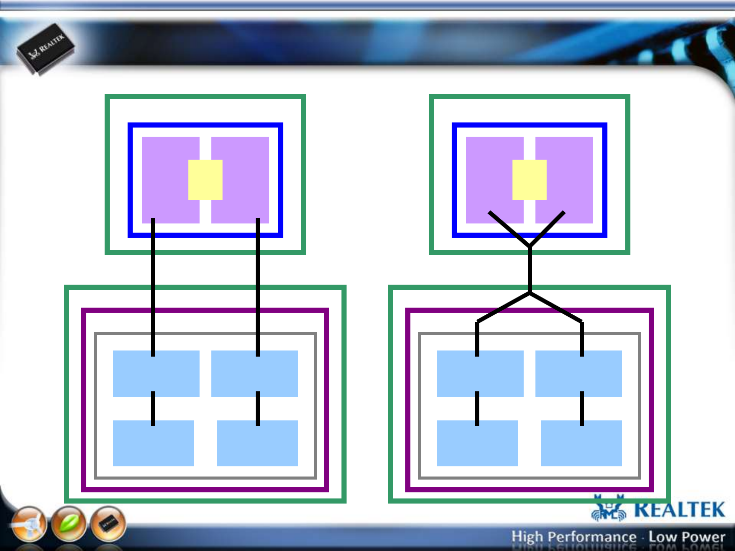
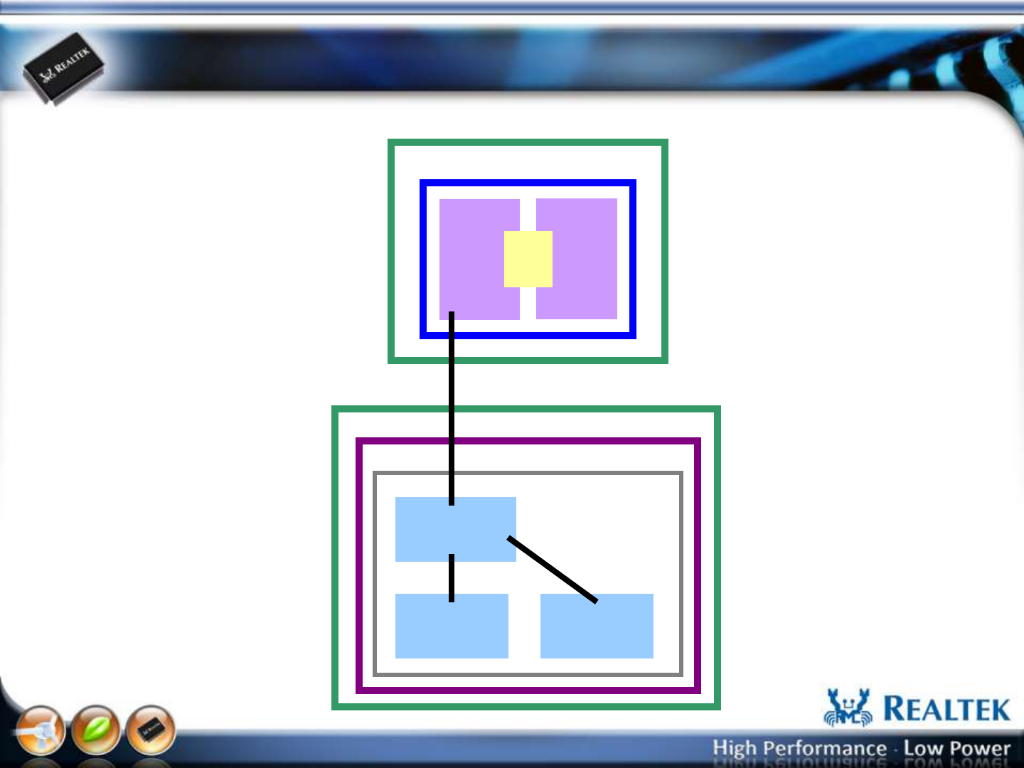
Host Interface: BT USB Port (8723AE,8723AE-VAU)
RTK BT
MP Driver
CPU
RTK WiFi
MP UI
WinXP/Win7
WiFi
FW BT
FW
Mail
box
RTL8723AE
8723AE WiFi
MP driver
PCIE
DUT
PC USB
RTK BT
MP UI
RTK BT
MP Driver
CPU
RTK WiFi
MP UI
WiFi
FW BT
FW
Mail
box
RTL8723AS-VAU
8723AS-VAU
WiFi MP driver
DUT
PC USB
RTK BT
MP UI
WinXP/Win7
-8-
Copyright © 2013 Realtek Semiconductor Corp.
www.realtek.com
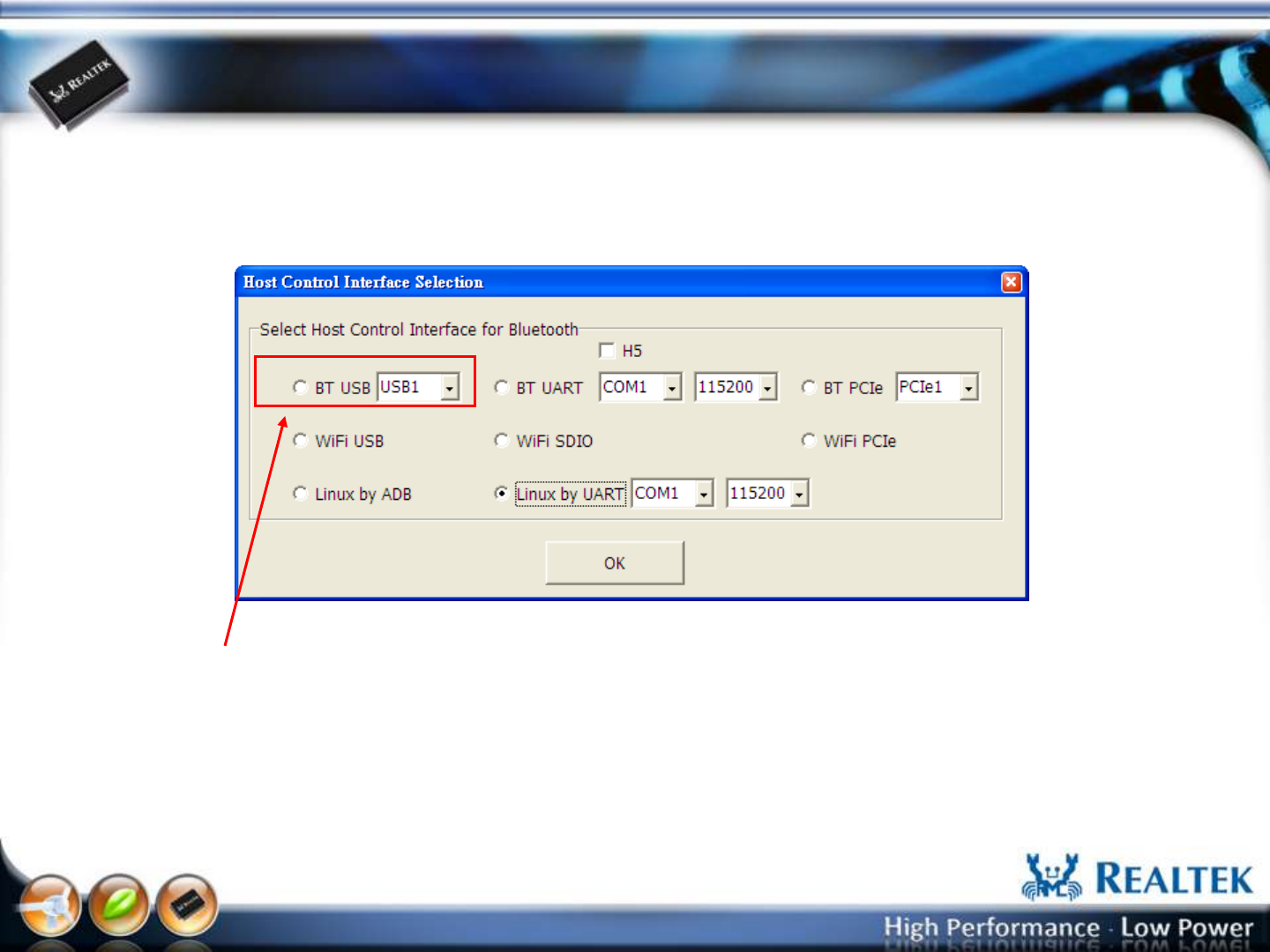
Host Interface: BT USB Port (8723AE,8723AE-VAU)
Select “BT USB” , Choose USB port number, and Press “OK” button to start the MP.
-9-
Copyright © 2013 Realtek Semiconductor Corp.
www.realtek.com
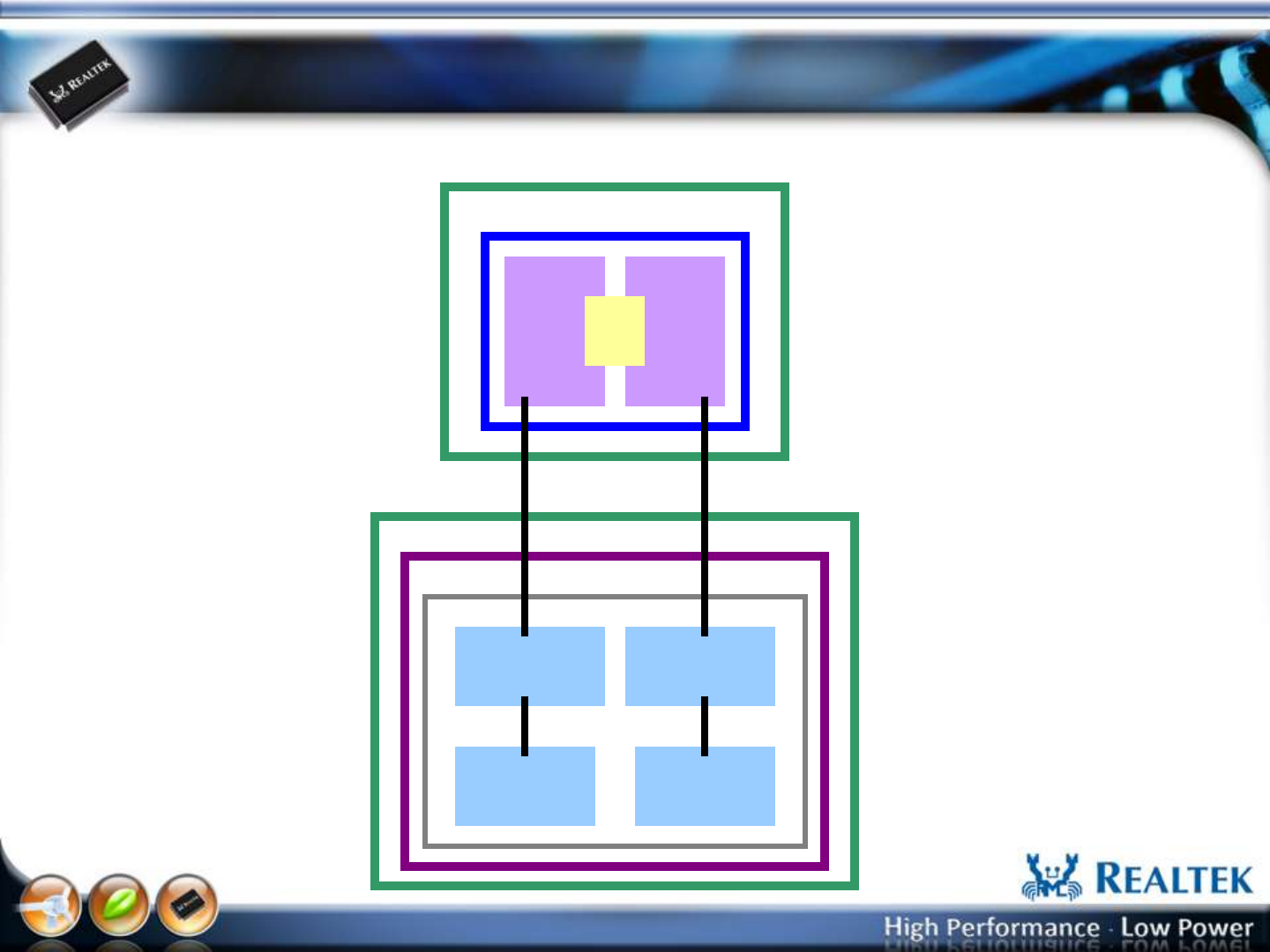
Host Interface: BT UART Port (8723AS)
RTK BT
MP Driver
CPU
RTK WiFi
MP UI
WinXP/Win7
WiFi
FW BT
FW
Mail
box
RTL8723AS
8723AS WiFi
MP driver
SDIO
DUT
PC UART
RTK BT
MP UI
-10-
Copyright © 2013 Realtek Semiconductor Corp.
www.realtek.com
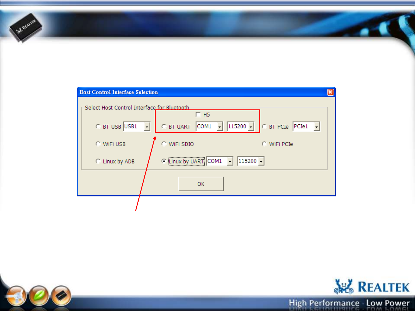
Host Interface: BT UART Port (8723AS)
Select “BT UART” , Choose COM port number and baud rate (default: 115200), and Press “OK”
button to start the MP.
-11-
Copyright © 2013 Realtek Semiconductor Corp.
www.realtek.com
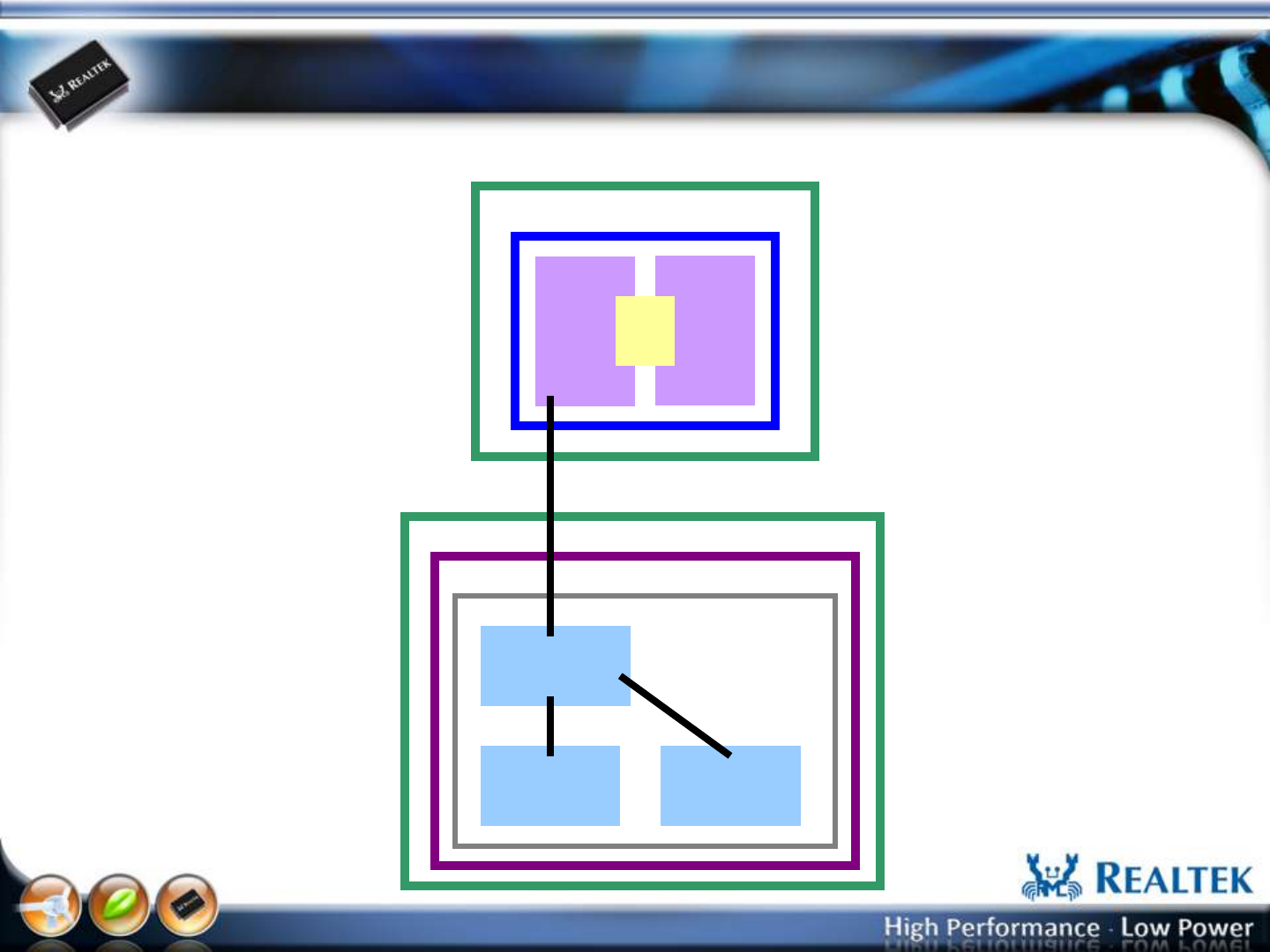
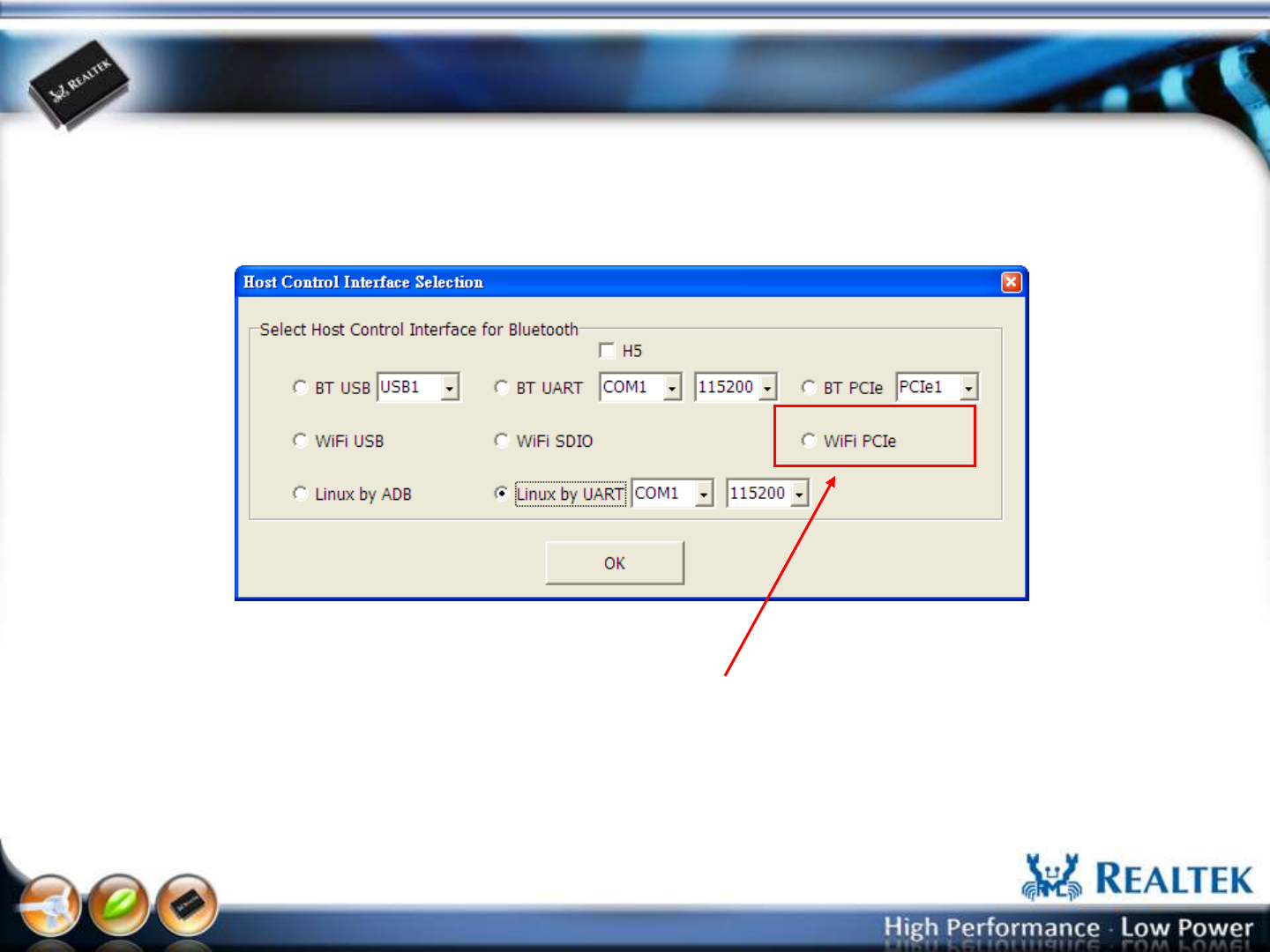
Host Interface: WiFi PCIe Port (8723AE)
CPU
RTK WiFi
MP UI
WiFi
FW BT
FW
Mail
box
RTL8723AE
8723AE
MP driver
PCIE
DUT
PC
RTK BT
MP UI
WinXP/Win7
-12-
Copyright © 2013 Realtek Semiconductor Corp.
www.realtek.com
Host Interface: WiFi PCIe Port (8723AE)
Select “WiFi PCIe” , and Press “OK” button to start the MP.
-13-
Copyright © 2013 Realtek Semiconductor Corp.
www.realtek.com
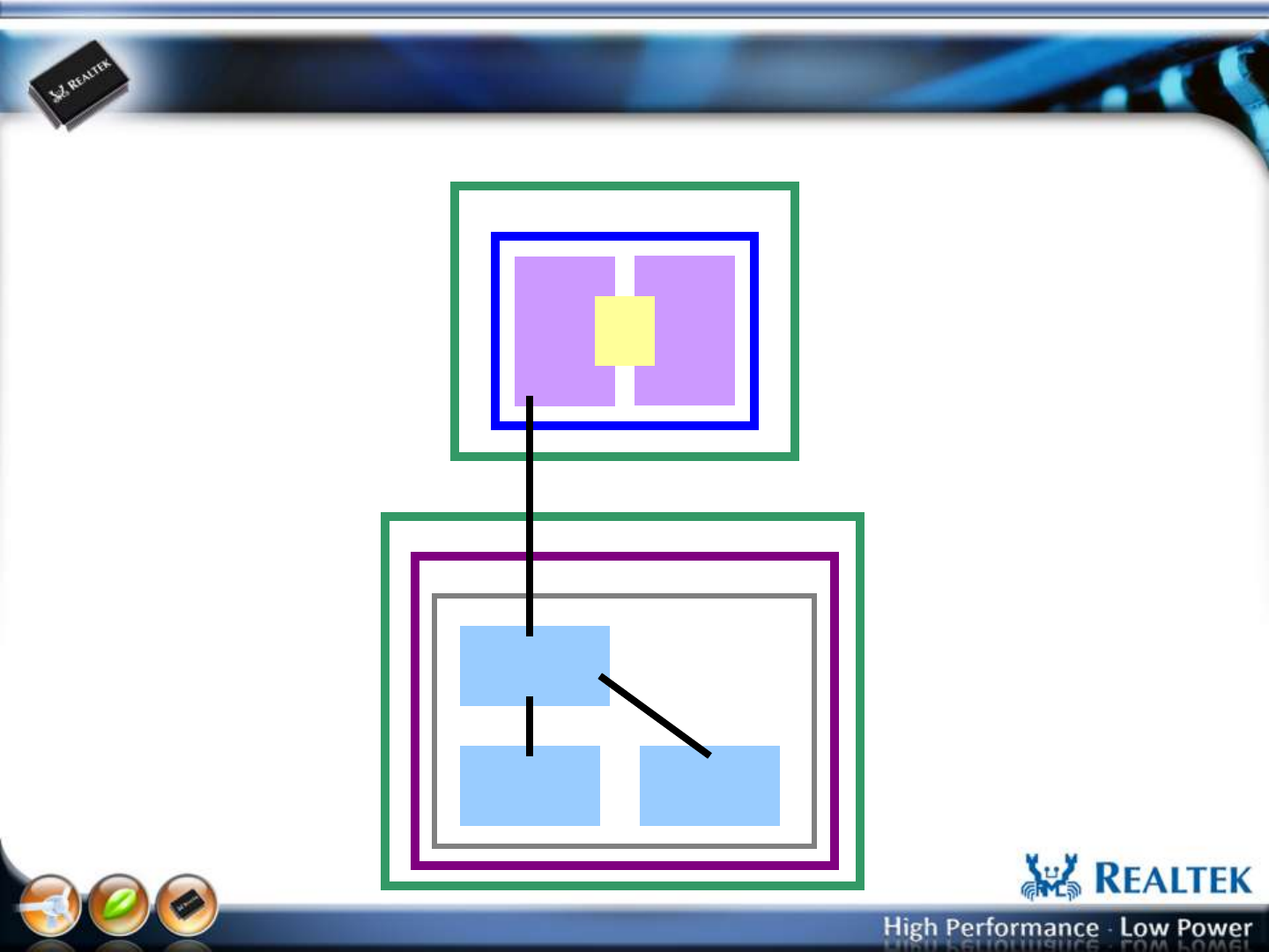
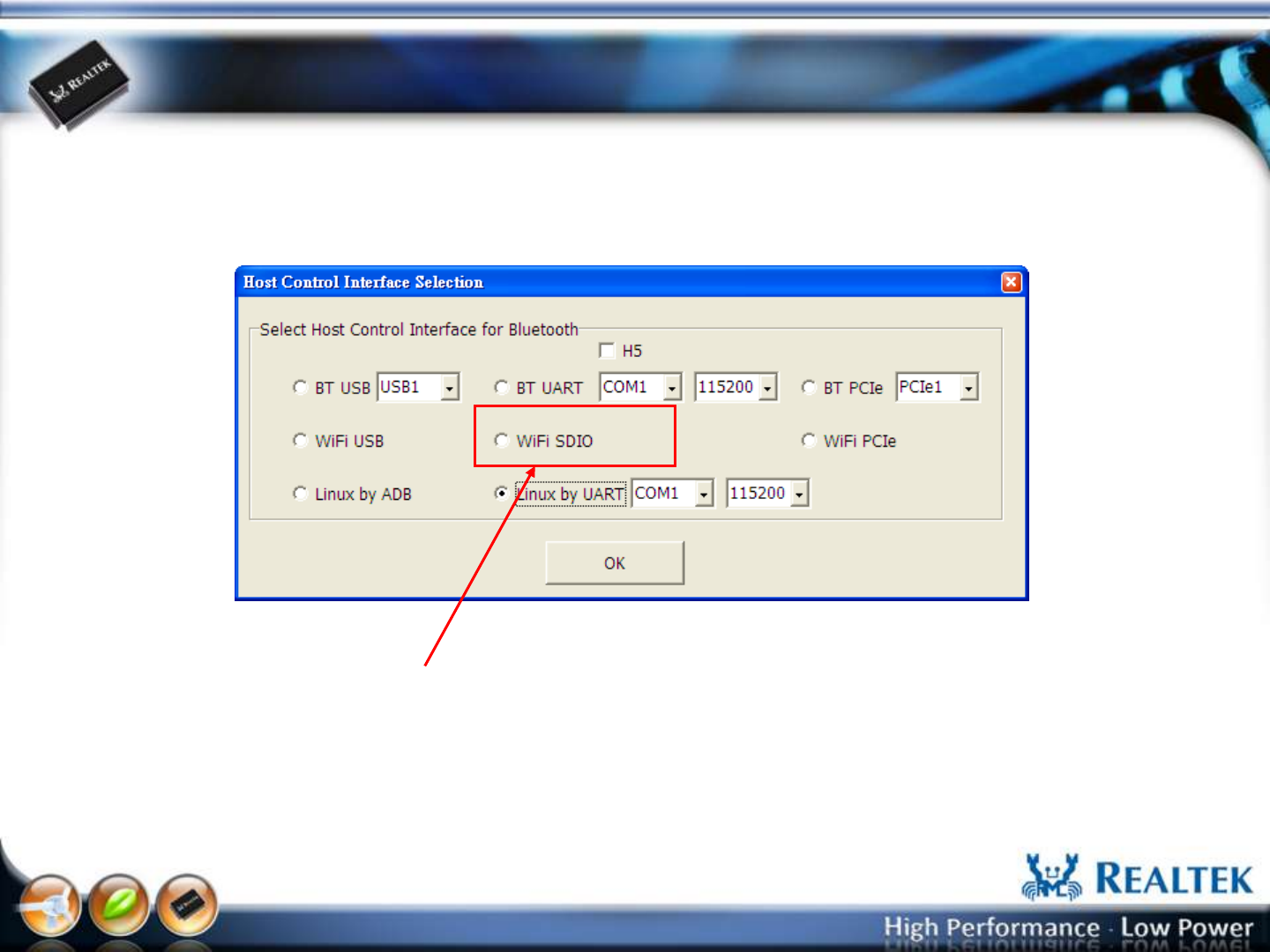
Host Interface: WiFi SDIO Port (8723AS)
CPU
RTK WiFi
MP UI
WiFi
FW BT
FW
Mail
box
RTL8723AS
8723AS
MP driver
SDIO
DUT
PC
RTK BT
MP UI
WinXP/Win7
-14-
Copyright © 2013 Realtek Semiconductor Corp.
www.realtek.com
Host Interface: WiFi SDIO Port (8723AS)
Select “WiFi SDIO” , and Press “OK” button to start the MP.
-15-
Copyright © 2013 Realtek Semiconductor Corp.
www.realtek.com
Host Interface: WiFi USB Port (8723AS-VAU)
CPU
RTK WiFi
MP UI
WiFi
FW BT
FW
Mail
box
RTL8723AS-VAU
8723AS-VAU
MP driver
USB
DUT
PC
RTK BT
MP UI
WinXP/Win7
-16-
Copyright © 2013 Realtek Semiconductor Corp.
www.realtek.com
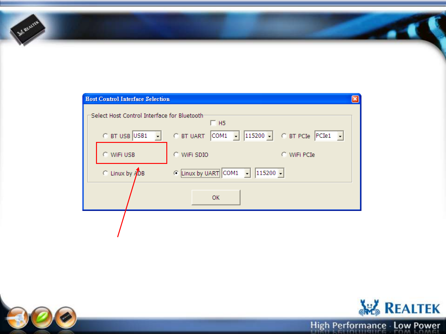
Host Interface: WiFi USB Port (8723AS-VAU)
Select “WiFi USB” , and Press “OK” button to start the MP.

-17-
Copyright © 2013 Realtek Semiconductor Corp.
www.realtek.com
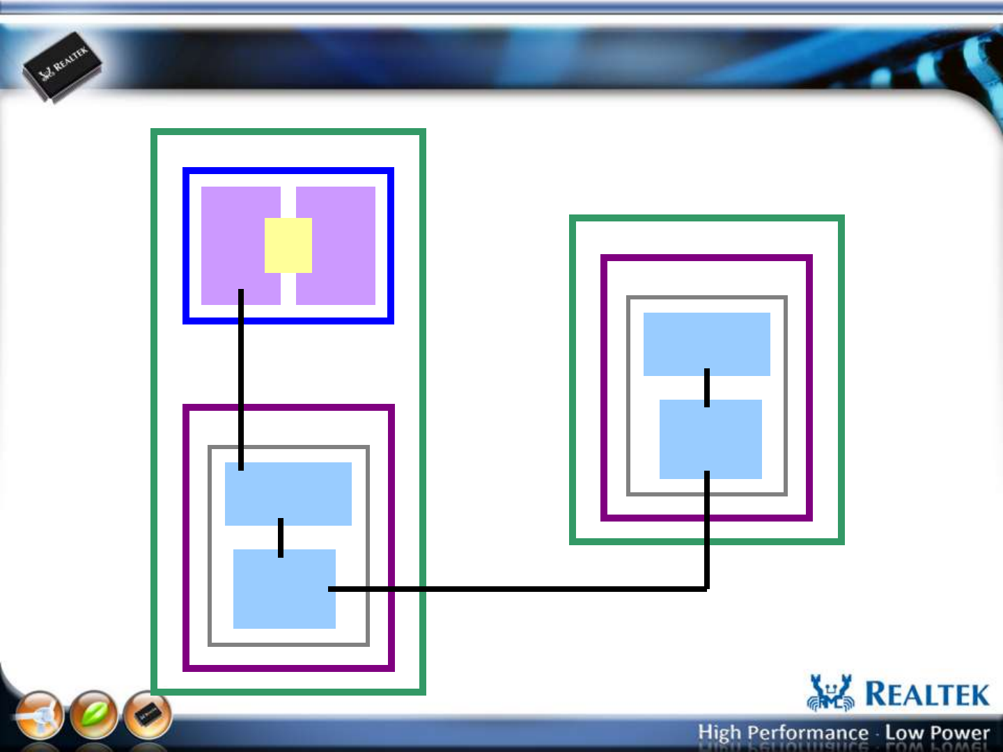
Host Interface: Linux USB Port (8723AS,8723AS-VAU)
USB
Port
CPU
RTK MP UI
WiFi
FW BT
FW
Mail
box
RTL8723AS/8723AS-VAU
Embedded System
8723AS WiFi
MP driver
SDIO/USB
USB
Port
Linux
USB Cable
PC
WinXP/Win7
-18-
Copyright © 2013 Realtek Semiconductor Corp.
www.realtek.com
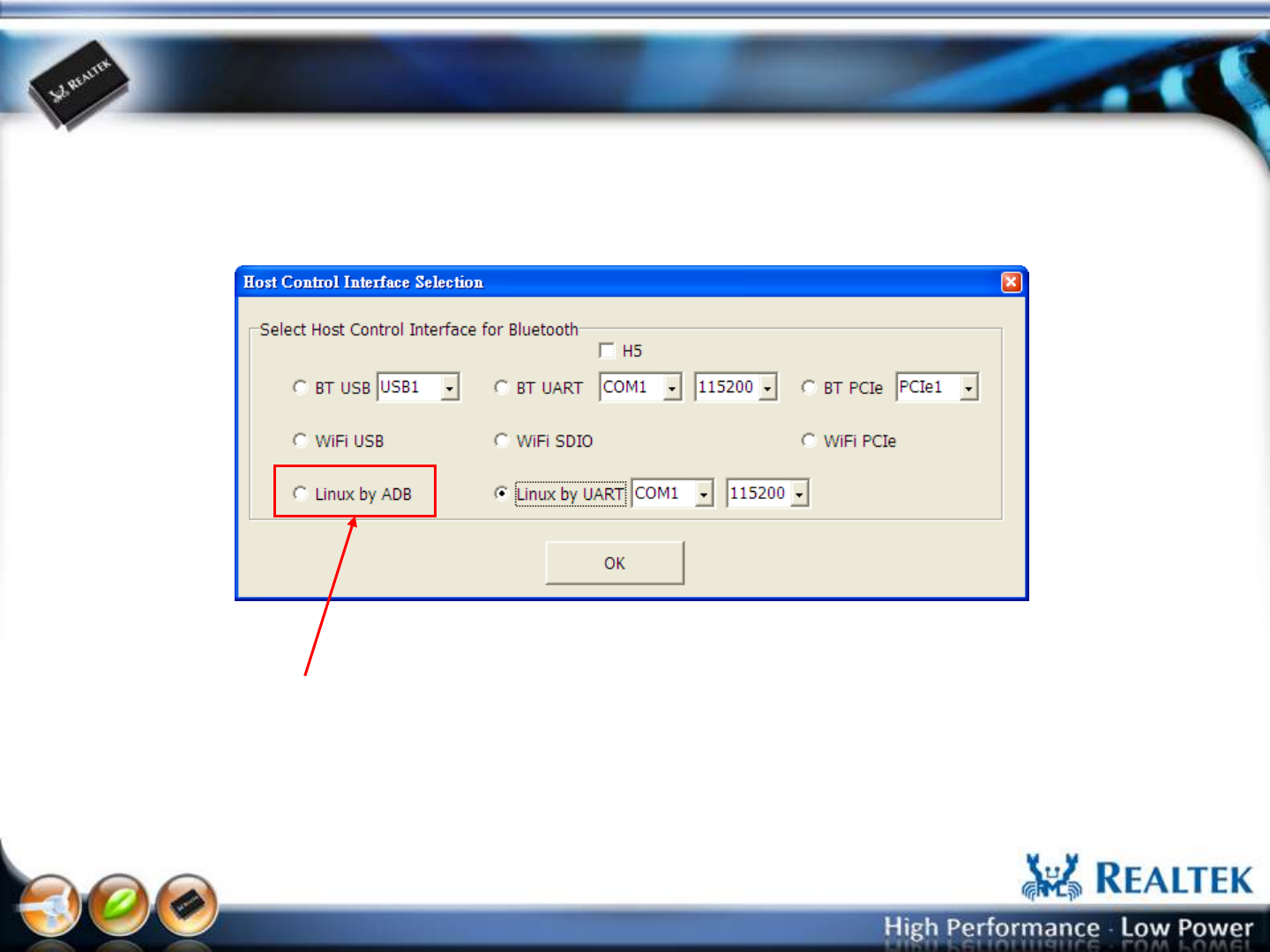
Host Interface: Linux USB Port (8723AS,8723AS-VAU)
Select “Linux by ADB” , and Press “OK” button to start the MP.
-19-
Copyright © 2013 Realtek Semiconductor Corp.
www.realtek.com
Host Interface: Linux COM Port (8723AS,8723AS-VAU)
COM
Port
CPU
RTK MP UI
WiFi
FW BT
FW
Mail
box
RTL8723AS/8723AS-VAU
Embedded System
8723AS WiFi
MP driver
COM
Port
Linux
RS232 Cable
PC
WinXP/Win7
SDIO/USB
-20-
Copyright © 2013 Realtek Semiconductor Corp.
www.realtek.com
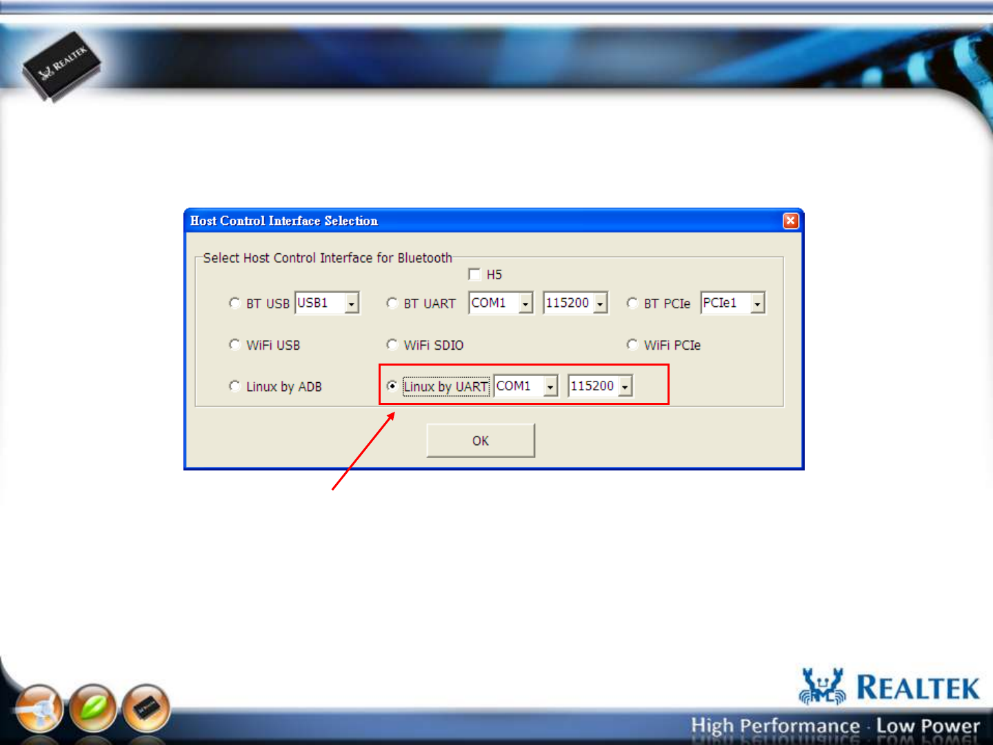
Select Host Control Interface
Select “Linux by UART” , Choose COM port number and baud rate (default: 115200), and
Press “OK” button to start the MP.
Note: It is recommended to press the “OK” button after the system boot completely.
-21-
Copyright © 2013 Realtek Semiconductor Corp.
www.realtek.com
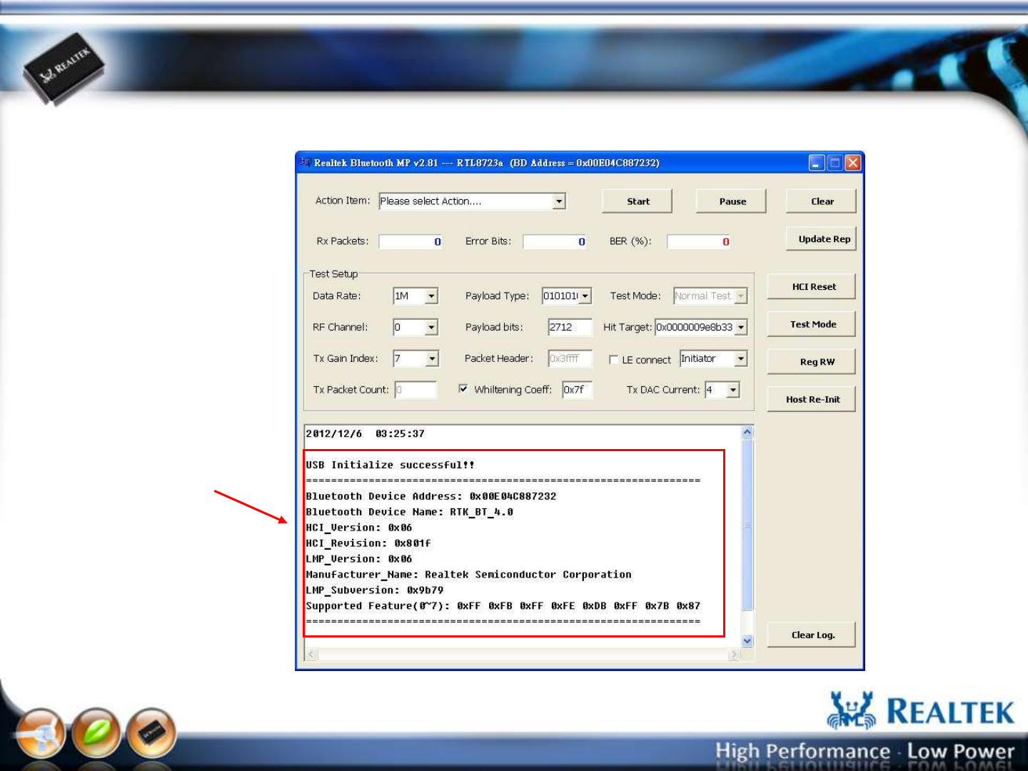
The Main UI (BT Host type)
If initial ok, memo show as
below
-22-
Copyright © 2013 Realtek Semiconductor Corp.
www.realtek.com
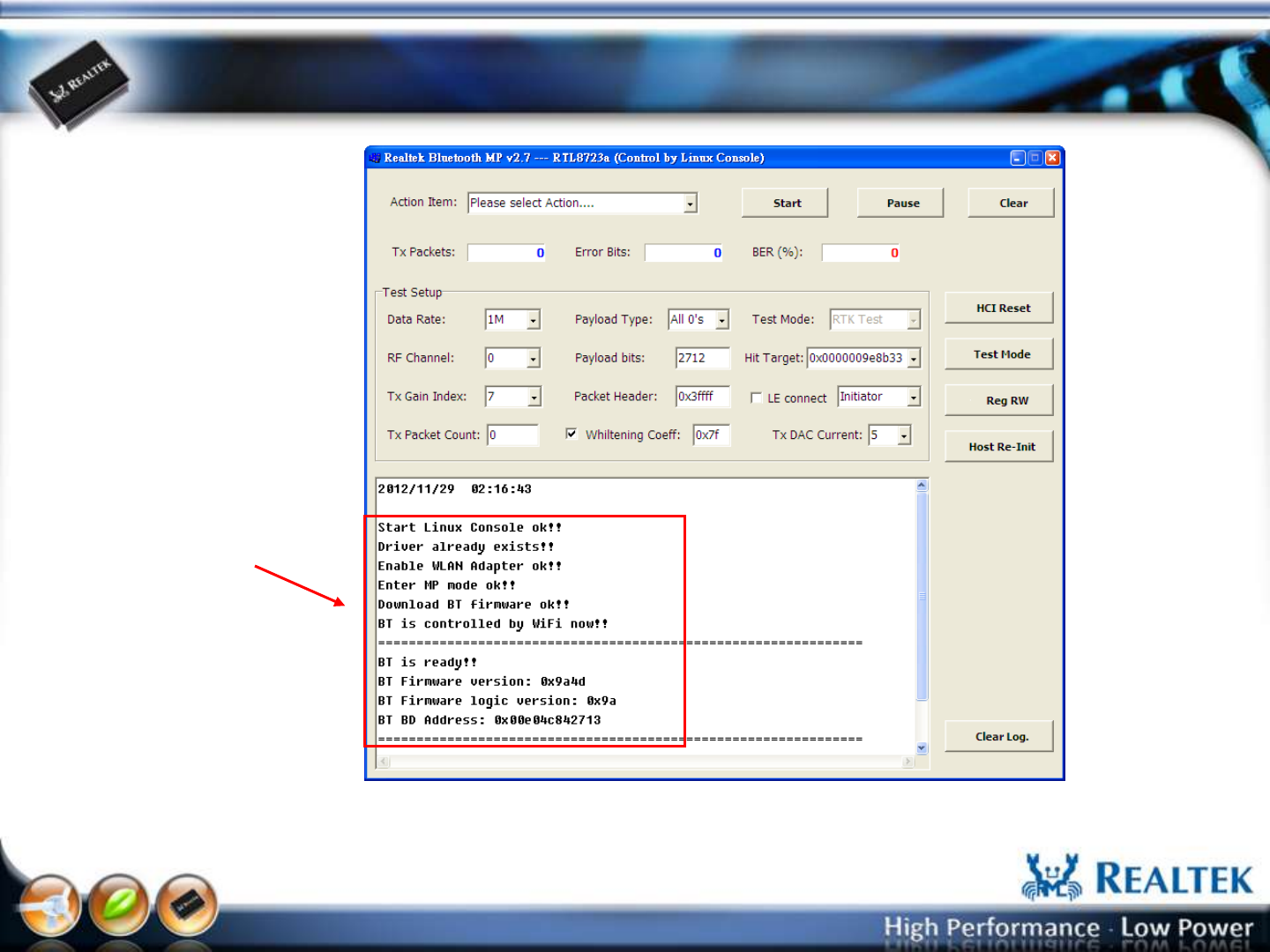
The Main UI (WiFi Host type)
If initial ok, memo show as
below
If initial fail, Check those:
a. RS232/USB cable
b. UART setup /USB port
c. BT Module
d. BT MP driver
Note: If initial fail (ex: enable WLAN adapter fail), it may result from the boot is not
completed during MP UI start. You can press “Host Re-Init” button or reopen the MP UI.

-23-
Copyright © 2013 Realtek Semiconductor Corp.
www.realtek.com
Bluetooth DUT Test Mode
Setup & Test Procedure
-24-
Copyright © 2013 Realtek Semiconductor Corp.
www.realtek.com
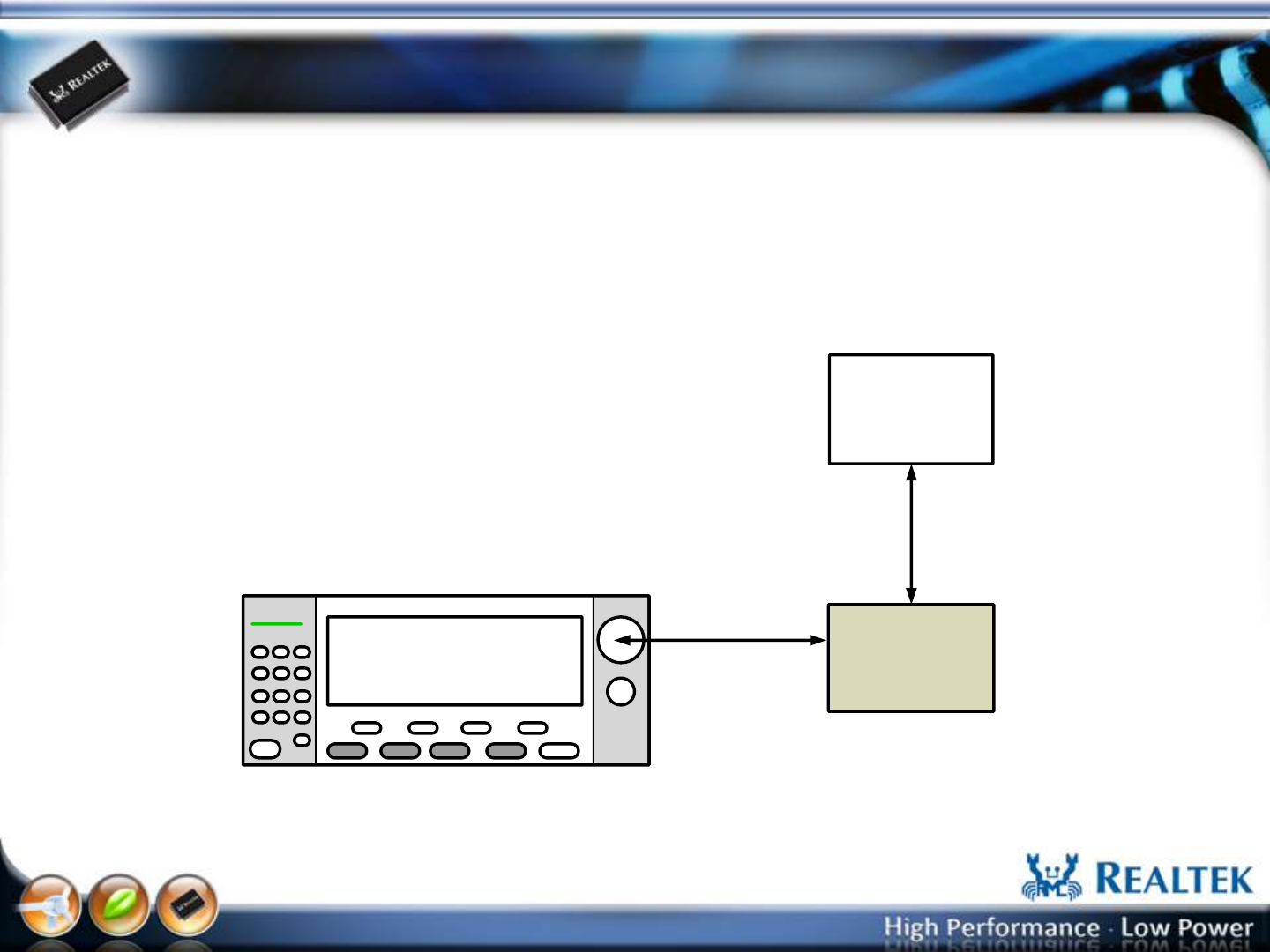
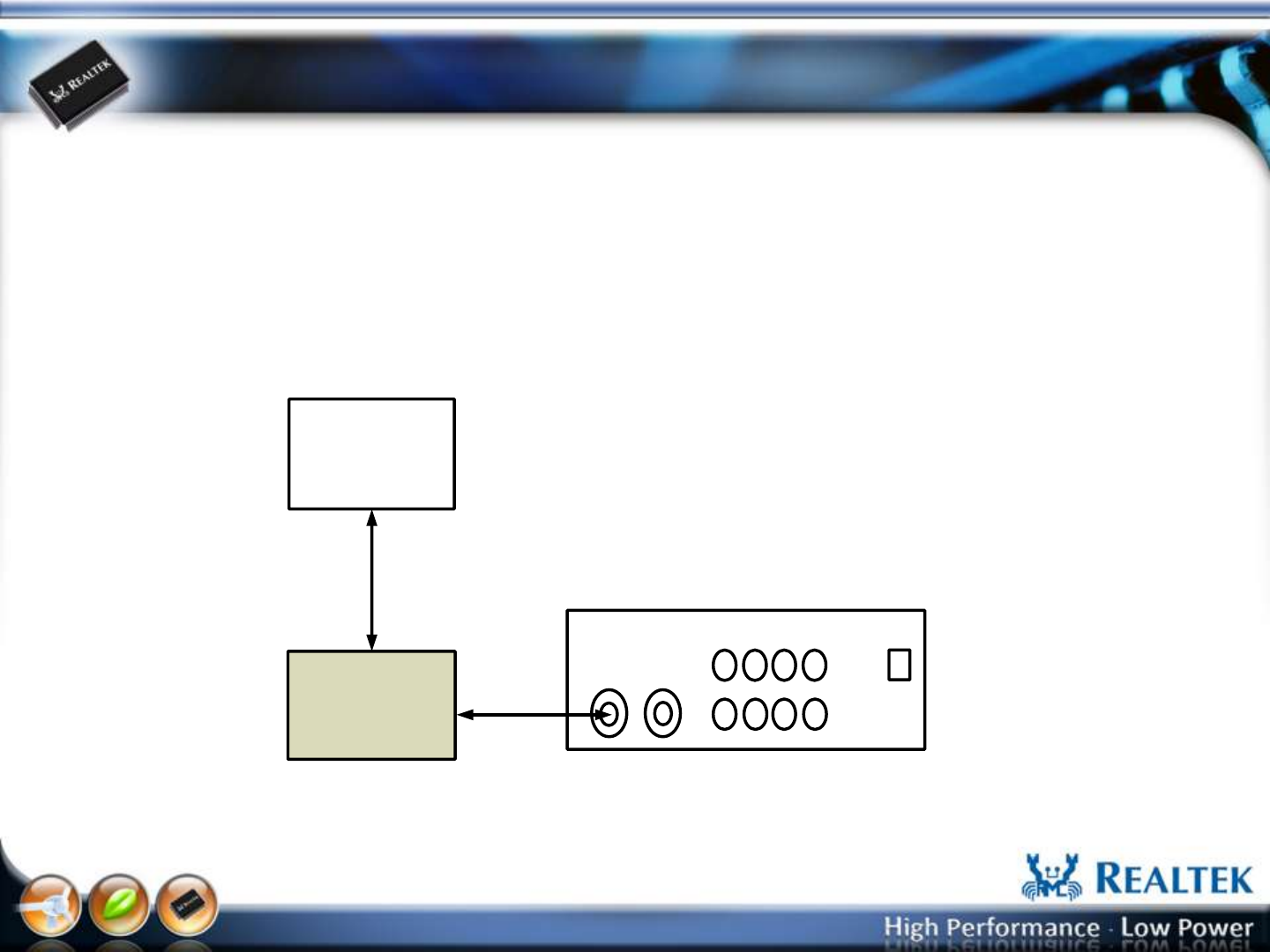
BT DUT Test Mode Test Topology
The BT MP sends BT HCI command to DUT. The DUT enable Inqr/Page
scan and enter DUT test mode. The Bluetooth tester established a link
with the DUT over the RF channel using the normal Bluetooth
protocol.
Bluetooth Test Set (ex:Anritsu MT8852B)
DUT
PC
(BT MP UI)
RF Cable
RS232 / USB
Cable
-25-
Copyright © 2013 Realtek Semiconductor Corp.
www.realtek.com
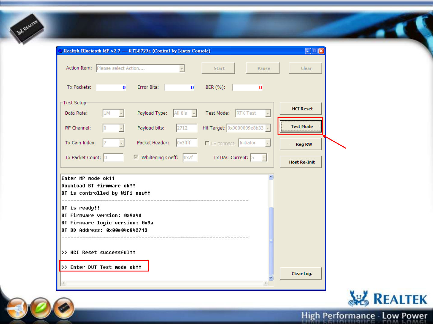
UI Setup Step-1: Enter DUT Test Mode
Press “Test Mode” button
To enter BT DUT test mode.
-26-
Copyright © 2013 Realtek Semiconductor Corp.
www.realtek.com
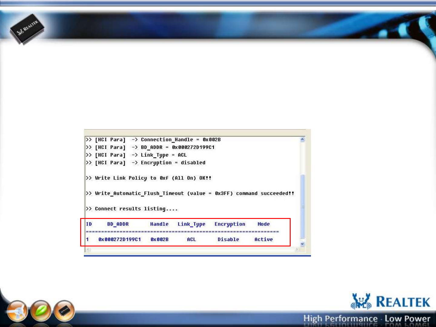
After UI Setup Step-1
After Bluetooth test set creates a connection with DUT, the BT MP UI will
show message as below. The RF test can kick off.
-27-
Copyright © 2013 Realtek Semiconductor Corp.
www.realtek.com
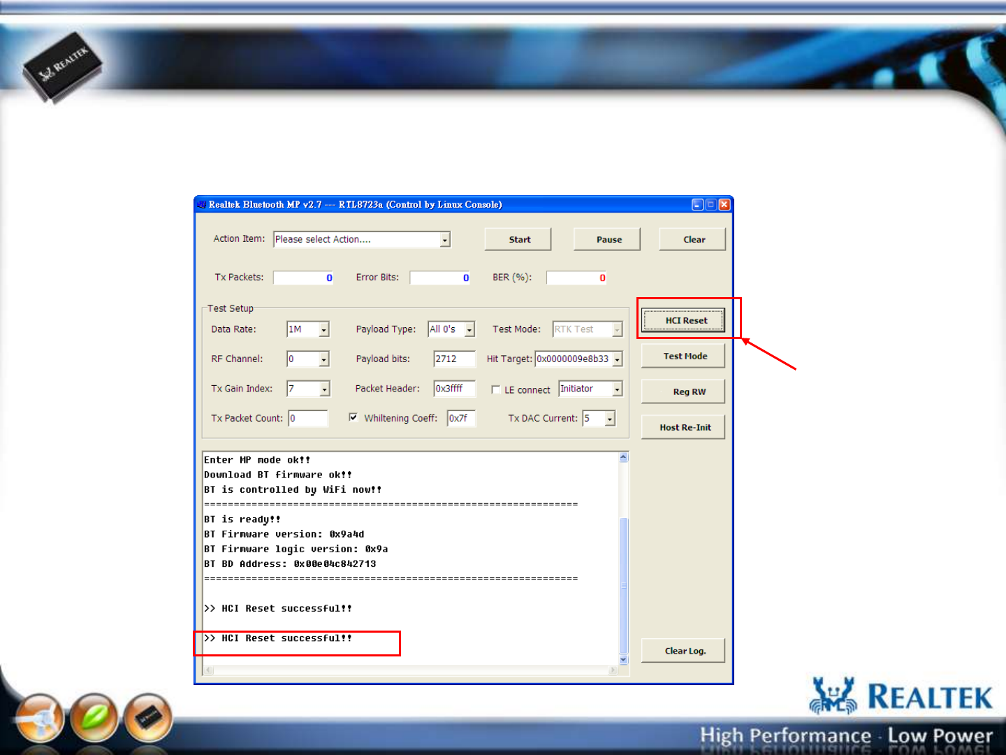
UI Setup Step-2: Exit DUT Test Mode (if required)
The connection can be disconnected by either BT test set or DUT. For DUT end,
the connection will lost because of supervision timeout after HCI reset is
executed.
Press “HCU Reset” button
To exit BT DUT test mode.

-28-
Copyright © 2013 Realtek Semiconductor Corp.
www.realtek.com
Bluetooth Non-Link Mode
Setup & Test Procedure
-29-
Copyright © 2013 Realtek Semiconductor Corp.
www.realtek.com
Non-Link Mode Test Topology
IQ View
DUT
PC
(BT MP UI)
RS232/USB
Cable
RF Cable
Bluetooth Test Set (ex:IQ view)
For non-link mode test, the tester communicates with DUT over a cable via HCI
with the DUT in a special test. The tester doesn’t have to establish a protocol link
with the DUT. The non-link mode of the 8723 series chip support “Packet-Tx”,
“Continue-Tx”, and “Packet-Rx” for various RF performance test.
-30-
Copyright © 2013 Realtek Semiconductor Corp.
www.realtek.com
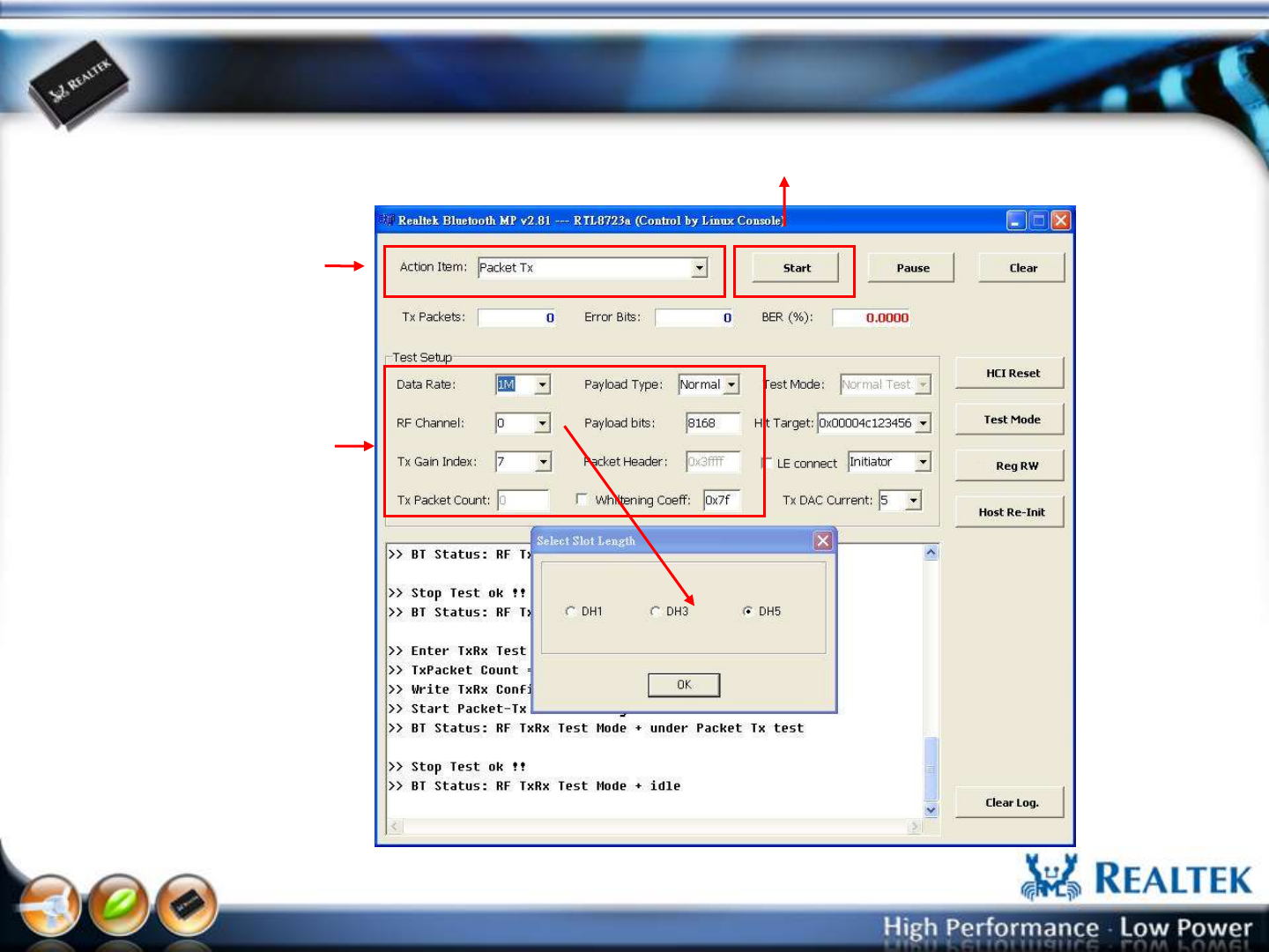
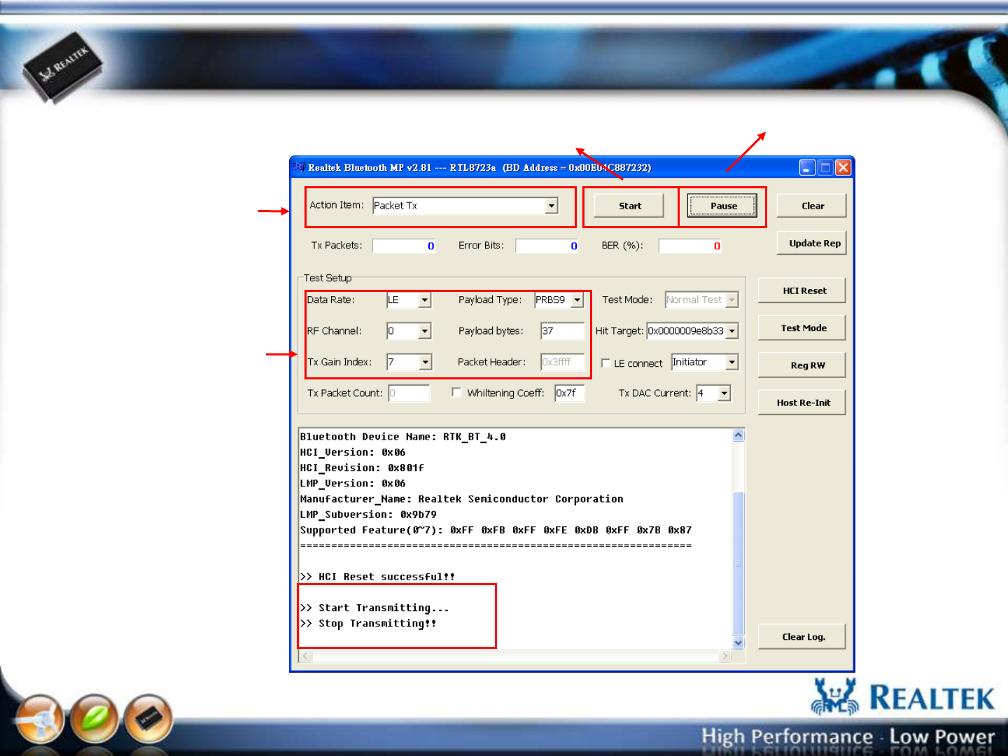
Packet-Tx Setup
Select “Packet-Tx” 1
2
3
Select “Data Rate”, “RF
Channel”, “Tx Gain Index”,
“Payload Type”, “Payload
bits”, “Whitening Coeff”
Press “Start” button
-31-
Copyright © 2013 Realtek Semiconductor Corp.
www.realtek.com
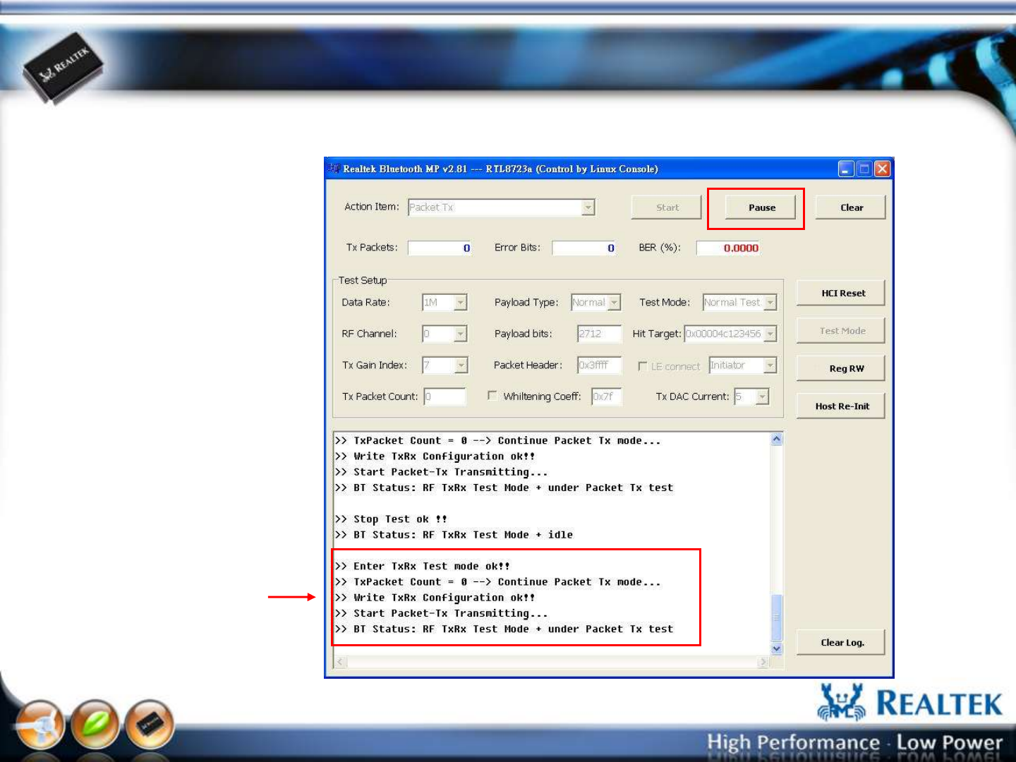
Packet-Tx Run
if “Packet-Tx” ok, the
message is shown as memo
“Packet-Tx” will stop after
press “Pause” button
-32-
Copyright © 2013 Realtek Semiconductor Corp.
www.realtek.com
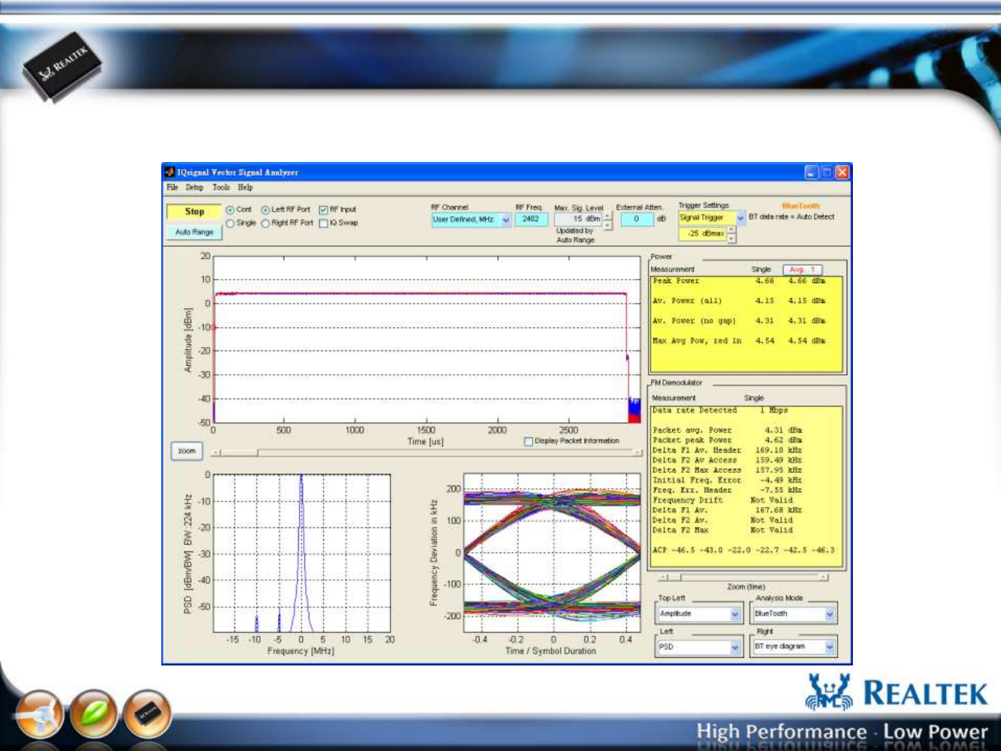
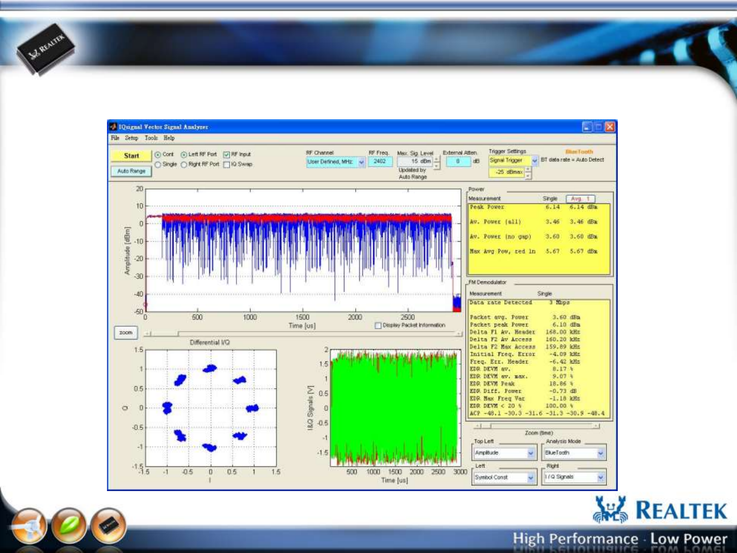
Packet-Tx Measurement form IQ view
Date Rate: 1M/DH5, RF Channel: 0, Payload Length:2712 bits, Payload Type:
11110000, Whitening: Off
-33-
Copyright © 2013 Realtek Semiconductor Corp.
www.realtek.com
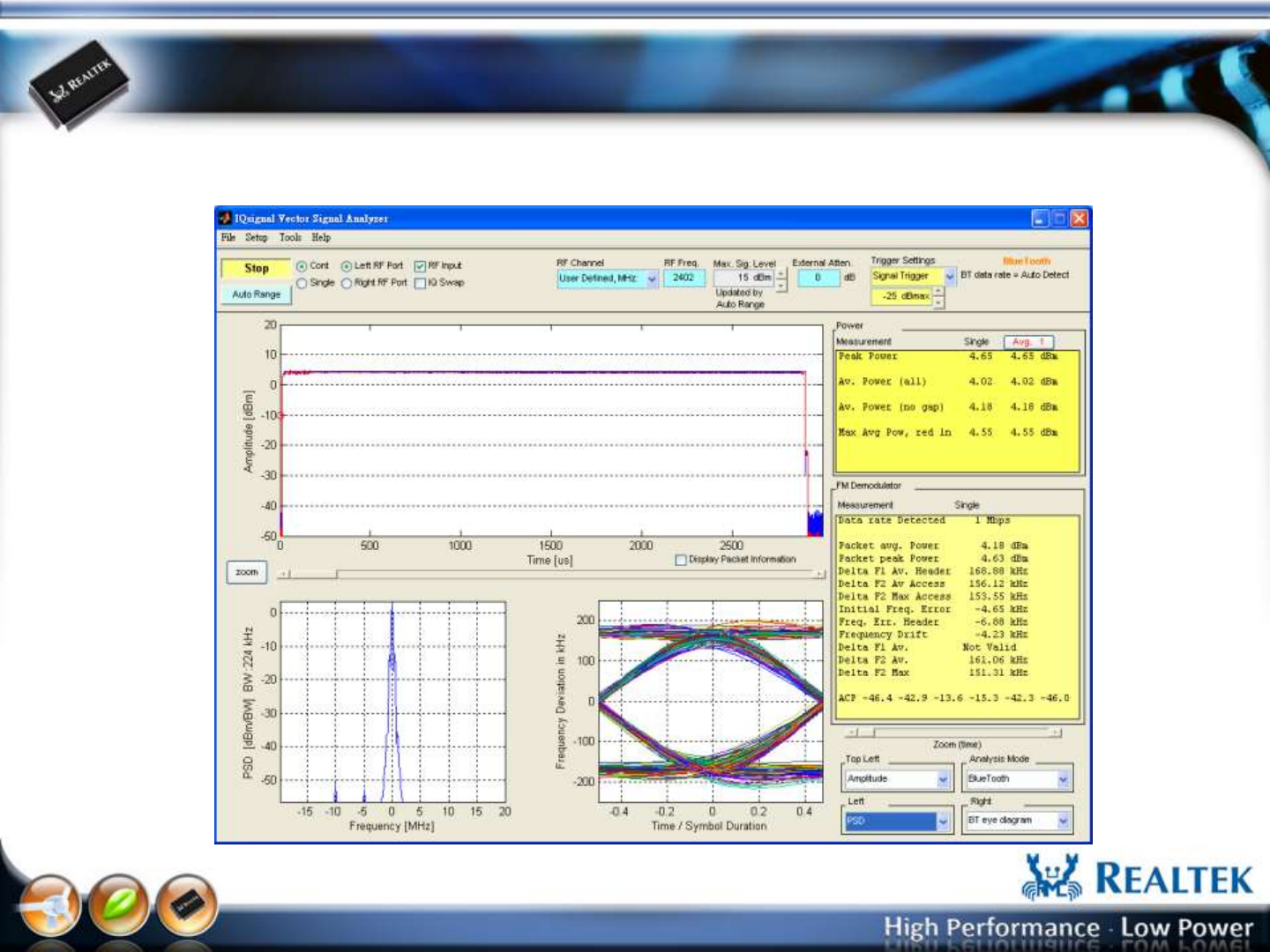
Packet-Tx Measurement form IQ view
Date Rate: 1M/DH5, RF Channel: 0, Payload Length:2712 bits, Payload Type:
10101010, Whitening: Off
-34-
Copyright © 2013 Realtek Semiconductor Corp.
www.realtek.com
Packet-Tx Measurement form IQ view
Date Rate: 3M/3DH5, RF Channel: 0, Payload Length:8168 bits, Payload Type:
Normal, Whitening: On
-35-
Copyright © 2013 Realtek Semiconductor Corp.
www.realtek.com
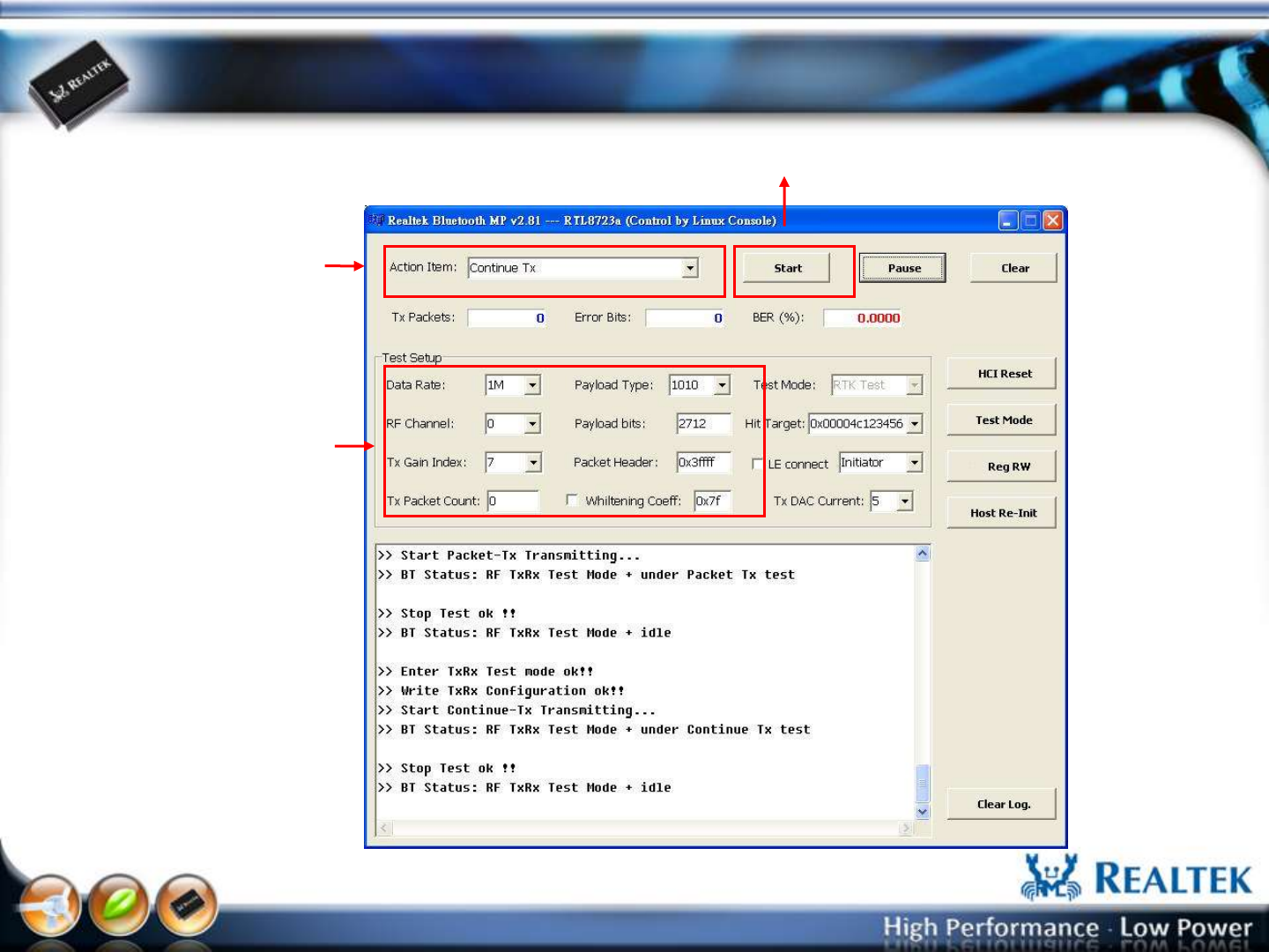
Continue-Tx Setup
Select “Continue-Tx” 1
2
3
Select “Data Rate”, “RF
Channel”, “Tx Gain Index”,
“Payload Type”
Press “Start” button
-36-
Copyright © 2013 Realtek Semiconductor Corp.
www.realtek.com
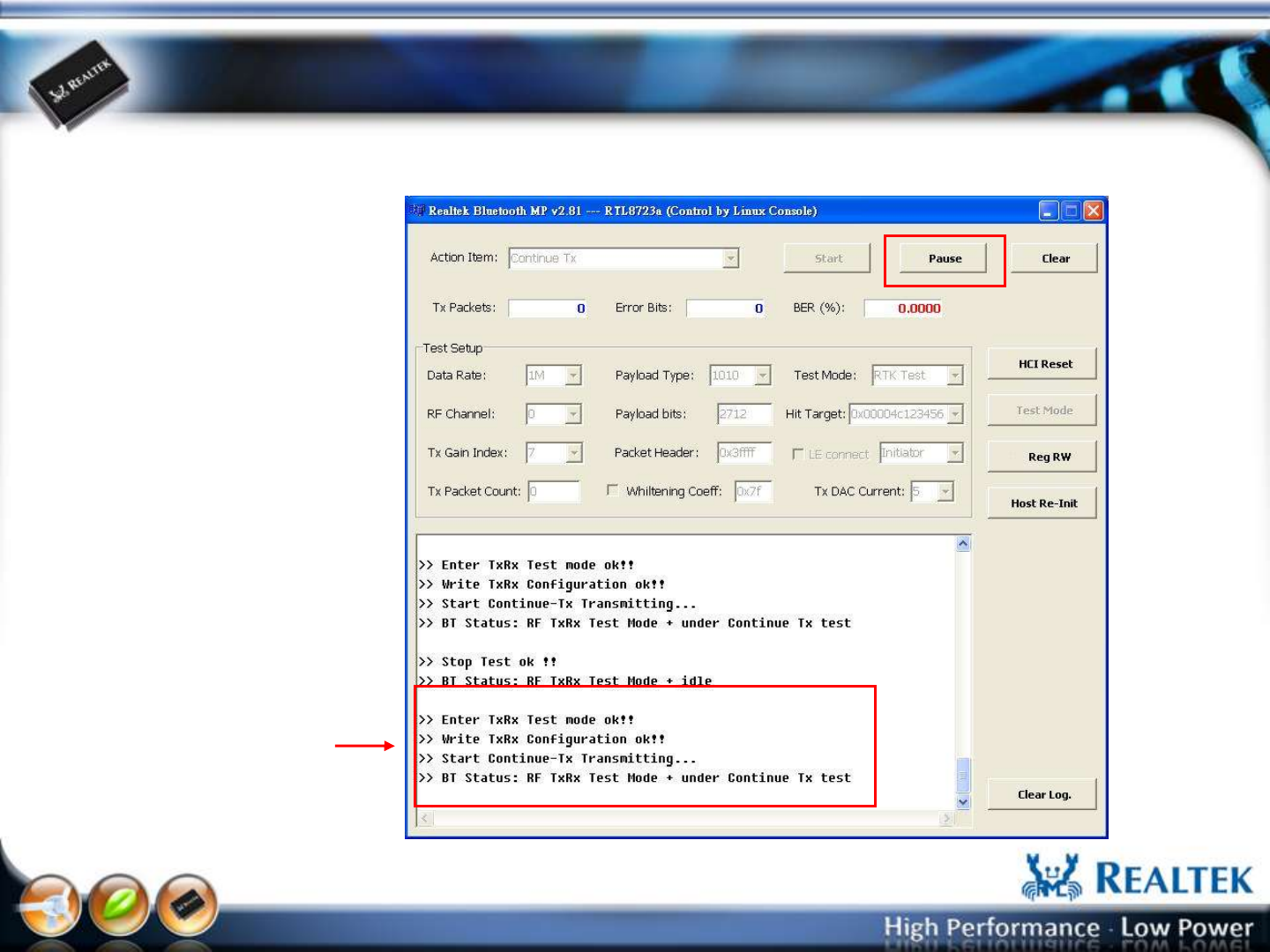
Continue-Tx Run
if “Continue-Tx” ok, the
message is shown as memo
“Continue-Tx” will stop
after press “Pause” button
-37-
Copyright © 2013 Realtek Semiconductor Corp.
www.realtek.com
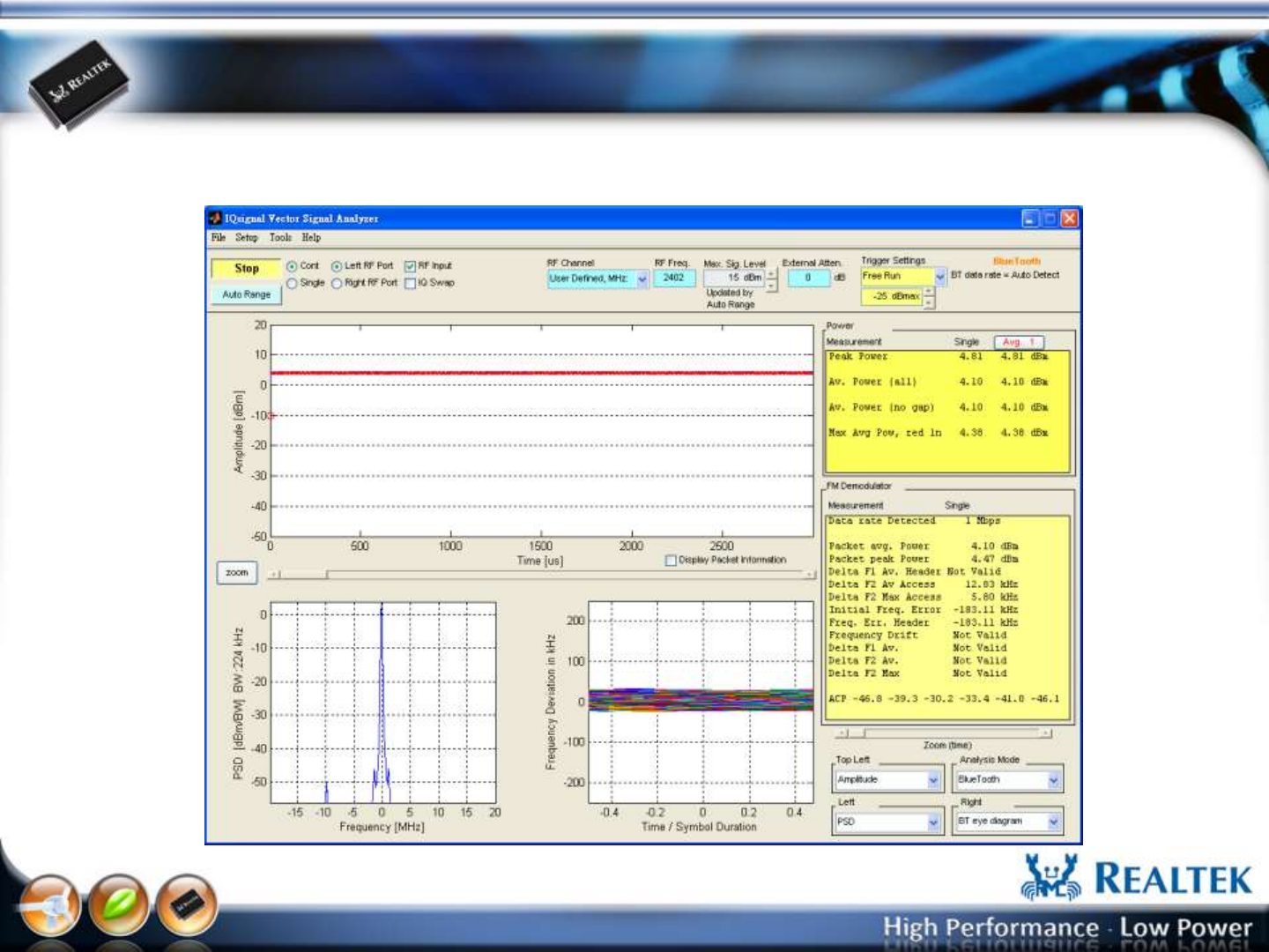
Continue-Tx Measurement form IQ view
“Continue-Tx” is used for Tx power measurement.
-38-
Copyright © 2013 Realtek Semiconductor Corp.
www.realtek.com
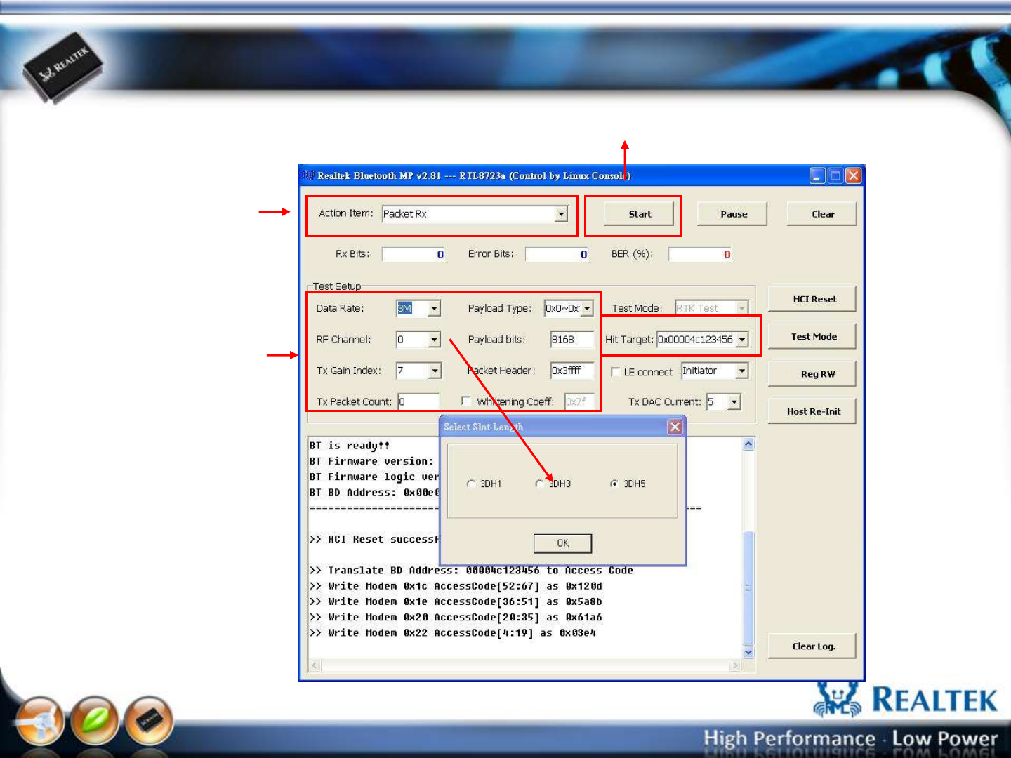
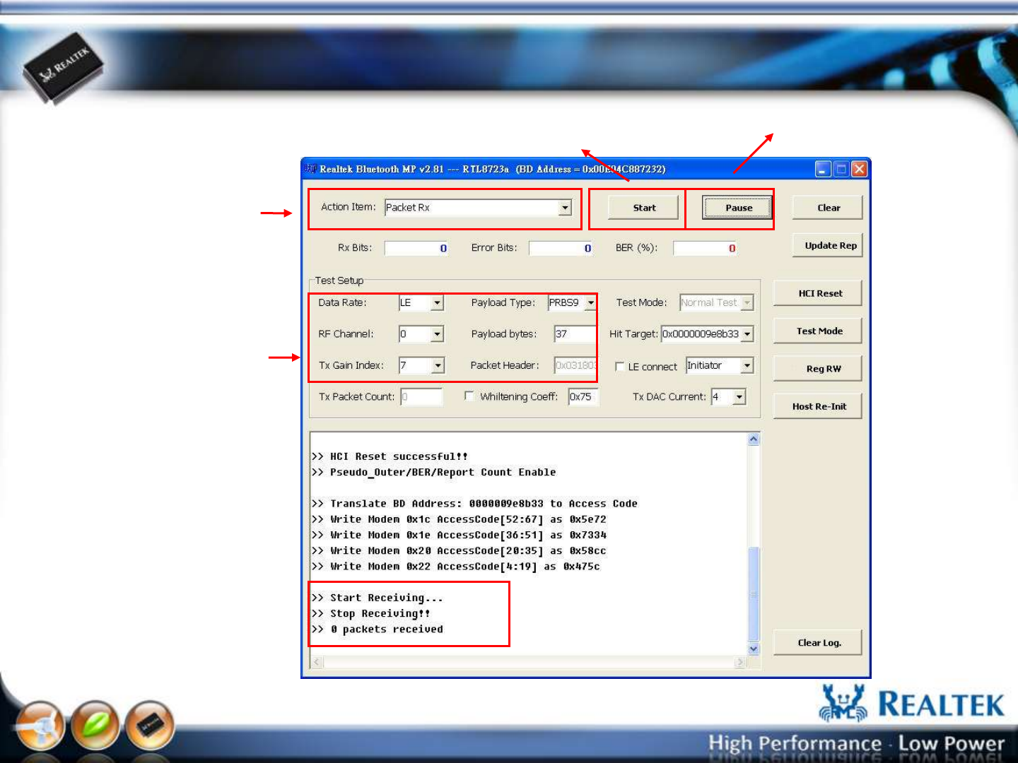
Packet-Rx Setup
Select “Packet-Rx” 1
2
3
Select “Data Rate”, “RF
Channel”, “Tx Gain Index”,
“Payload Type”, “Payload
bits”, “Whitening Coeff”,
“Hit Target”
“Hit Target” is BD address
that the BT tester used it to
generate the access code of
the test pattern.
These parameters must
meet with the BT tester’s
pattern.
Press “Start” button
-39-
Copyright © 2013 Realtek Semiconductor Corp.
www.realtek.com
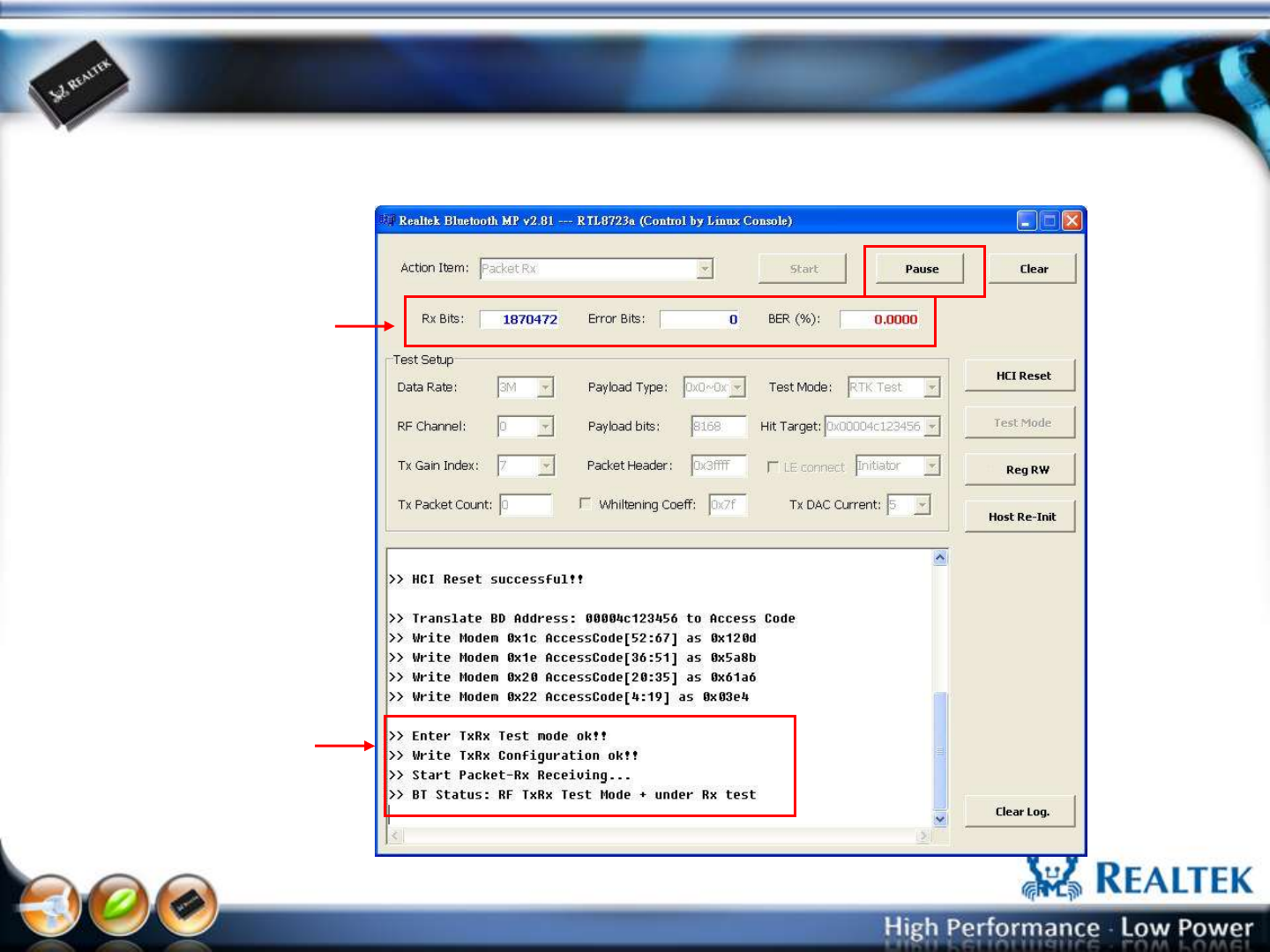
Packet-Rx Run
if “Packet-Rx” ok, the
message is shown as memo
“Packet-Rx” will stop after
press “Pause” button
“Packet-Rx” test result
-40-
Copyright © 2013 Realtek Semiconductor Corp.
www.realtek.com
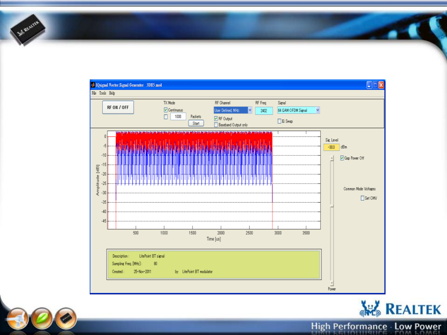
IQ view Vector Signal Generator
Used the IQ view Vector Signal Generator to generate test pattern (*.mod)

-41-
Copyright © 2013 Realtek Semiconductor Corp.
www.realtek.com
Bluetooth BT 4.0 LE
Direct Test Mode Setup
For RF/PHY Testing
-42-
Copyright © 2013 Realtek Semiconductor Corp.
www.realtek.com
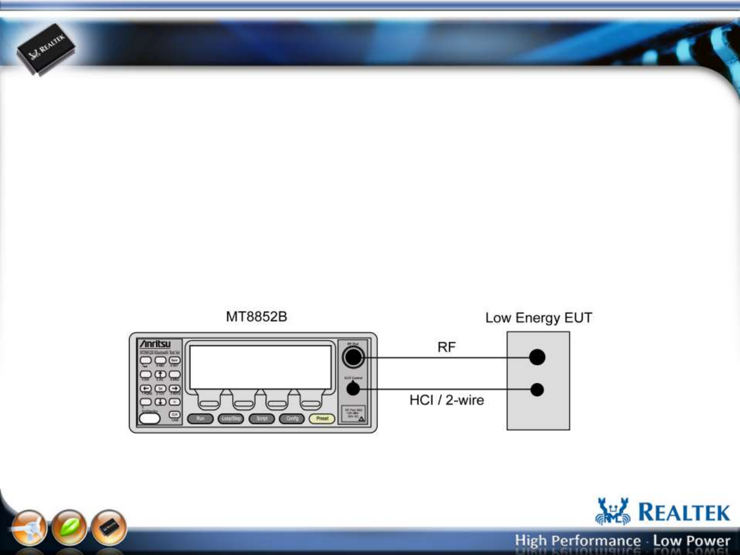
Most BT testers support host control port (USB,UART) that can be as
a ”upper tester” defined in the direct test mode of BT specifications. The
diagram shown as below is the MT8852B test configuration for LE RF/PHY test.
The BT MP also supports Tx and Rx test when the BT tester can not be a
“upper tester” (no host control port, ex: IQ view).
-43-
Copyright © 2013 Realtek Semiconductor Corp.
www.realtek.com
Tx Test Setup:
Select “Packet-Tx” 1
2
3
Select “Data Rate”, “RF
Channel”, “Tx Gain Index”,
“Payload Type”, “Payload
bytes”
“Date Rate” = [LE]
Press “Start” to start Tx and BT
tester can start measurement. 4
Press “Stop” to stop Tx.
-44-
Copyright © 2013 Realtek Semiconductor Corp.
www.realtek.com
Rx Test Setup:
Select “Packet-Rx” 1
2
3
Select “Data Rate”, “RF
Channel”, “Payload Type”,
“Payload bytes”
“Date Rate” = [LE]
Press “Start” to start Rx and BT
tester can start sending packet. 4
Press “Stop” to stop Rx.

-45-
Copyright © 2013 Realtek Semiconductor Corp.
www.realtek.com
BT 4.0 LE Setup
For FCC AFH Measurement
-46-
Copyright © 2013 Realtek Semiconductor Corp.
www.realtek.com
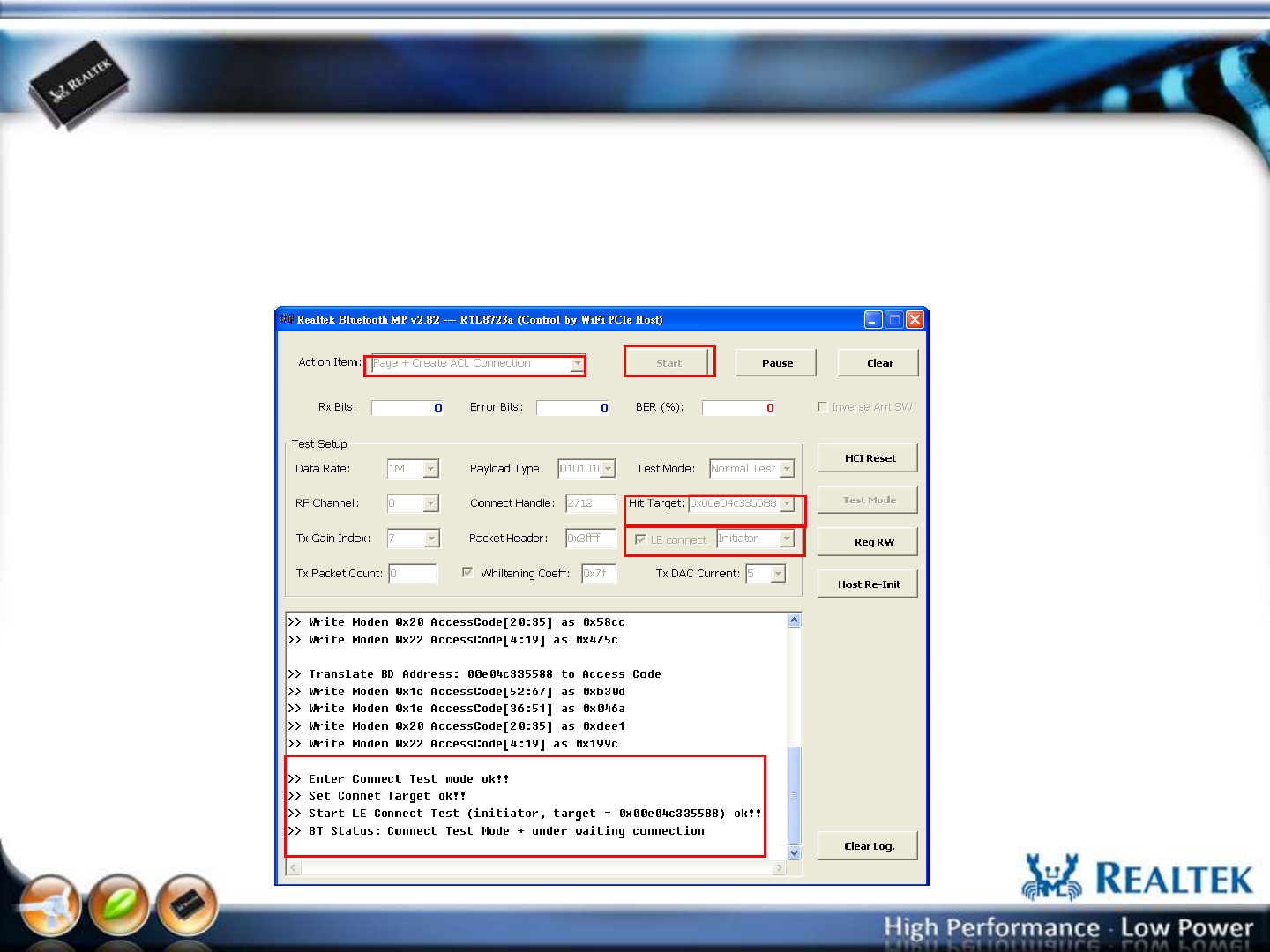
Step 1: Create LE connection (Initiator)
1. Checked [LE connect] and select “Initiator”.
2. Key in the Target BD Address in the [Hit Target] and press “Enter” key
3. In the Action Items, select “Page + Create ACL connection”
4. press [Start] button
1.
3. 4.
2.
-47-
Copyright © 2013 Realtek Semiconductor Corp.
www.realtek.com
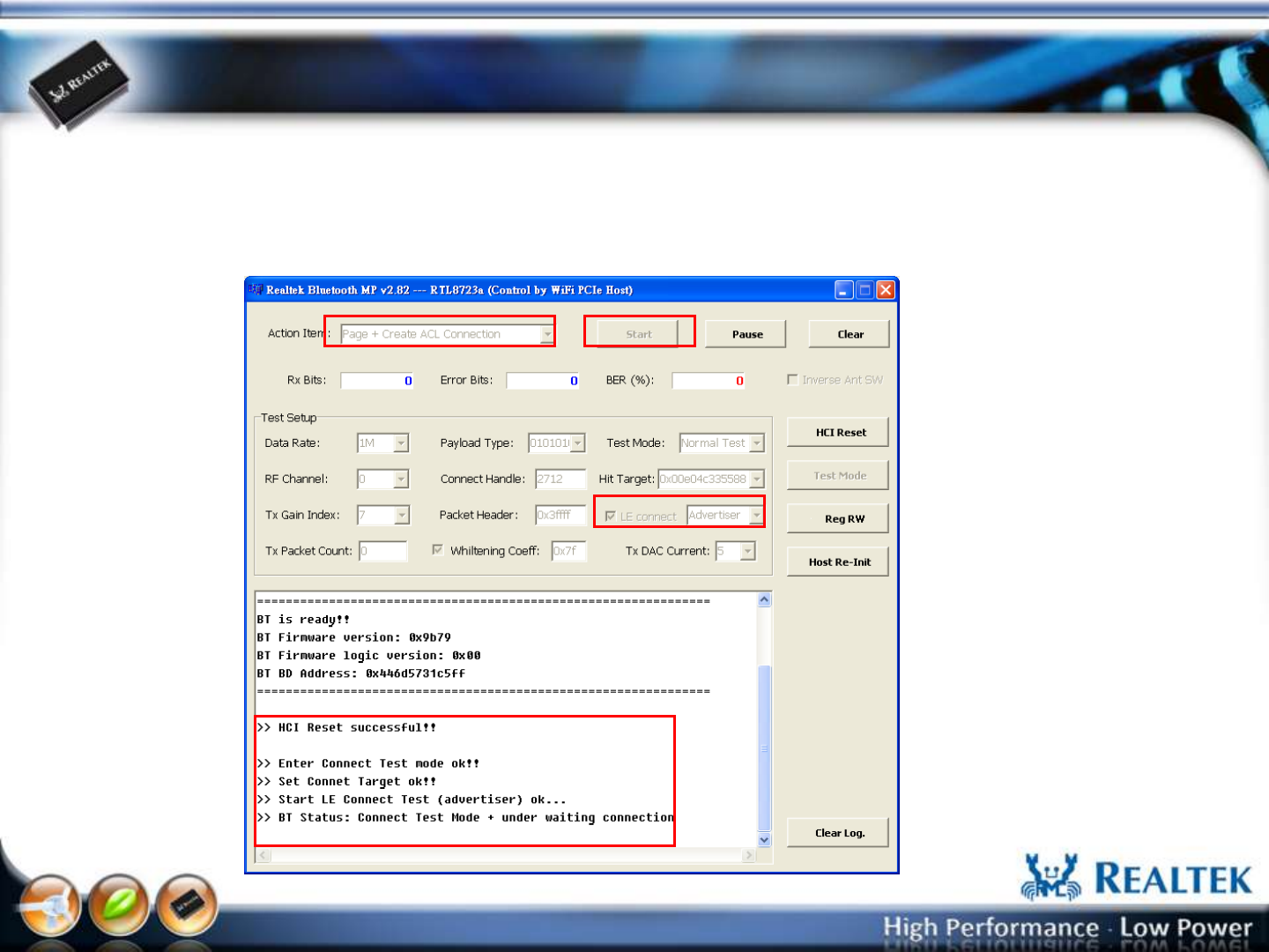
Step 2: Create LE connection (Advertiser)
1. Checked [LE connect] and select “Advertiser”.
2. In the Action Items, select “Page + Create ACL connection”
3. press [Start] button
1.
2. 3.
-48-
Copyright © 2013 Realtek Semiconductor Corp.
www.realtek.com
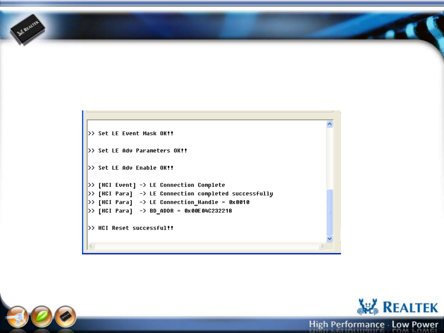
Step 3: Create LE connection
Initiator will create LE connection with Advertiser and AFH start running.
-49-
Copyright © 2013 Realtek Semiconductor Corp.
www.realtek.com
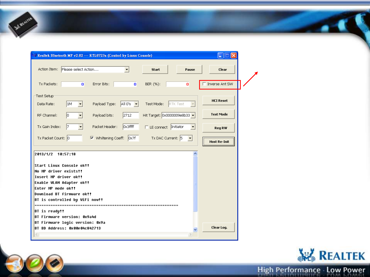
Setup Antenna Switch (support after v2.82)
If Checked: Main WiFi
else Main BT

FCC Warning Statement
Changes or modifications not expressly approved by the party responsible for complia nce could void the
user’s authority to operate the equipment. This equipment has been tested and found to comply with the
limits for a Class B digi tal device, pursuant to Part 15 of the FCC Rules. These limits are designed to provide
reasonable protection against harmful interference in a residential installation. This eq uipment generates uses
and can radiate radio frequency energy and, if not installed an d used in accordance with the instructions,
may cause harmful interference to radio co mmunications. However, there is no guarantee that interference
will not occur in a par ticular installation. If this equipment does cause harmful interference to radio or televi
sion reception, which can be determined by turning the equipment off and on, the user is encouraged to try
to correct the interference by one or more of the following measu res: ‐ Reorient or relocate the receiving antenna.
‐Increase the separation between the equipment and receiver.
‐ Connect the equipment into an outlet on a circuit different from that to which the receiver is connected.
‐ Consult the dealer or an experienced radio/TV technician for help.
This module is intended for OEM integrator. The OEM integrator is still responsible for the FCC compliance requirement
of the end product which integrates this module.
The final end product must be labeled in a visible area with the following" Contains TX FCC ID: 2AC23-WT4XR1210".
The FCC part 15.19 statement below has to also be available on the label: This device complies with Part 15 of FCC rules.
Operation is subject to the following two conditions: (1) this device may not cause harmful interference and
(2) this device must accept any interference received, including interference that may cause undesired operation.
The end user has to be informed that the FCC radio-frequency exposure guidelines for an uncontrolled environment can be satisfied. The end
user has to also be informed that any changes or modifications not expressly approved by the manufacturer could void the user's authority to
operate this equipment.