HUNAN FN LINK TECHNOLOGY F88FTUM13 Wifi Module User Manual
FN-LINK TECHNOLOGY LIMITED Wifi Module Users Manual
15_F88FTUM13 UserMan, r3.pdf
F88FTUM13

FN-LINK TECHNOLOGY LIMITED
http://www.fn-link.com Page2/12
CONTENTS
0 REVESION HISTORY.......................................................................................................................................3
1 INTRODUCTIONS.............................................................................................................................................4
1.1 OVERVEIW...................................................................................................................................................4
1.2 PRODUCT FEATURES.............................................................................................................................. 4
2 GENERAL SPECIFICATION............................................................................................................................4
2.1 WIFI RF SPECIFICATION..........................................................................................................................4
2.2 POWER CONSUMPTION..........................................................................................................................5
3 MECHANICAL SPECIFICATION.................................................................................................................... 6
3.1 OUTLINE DRAWING...................................................................................................................................6
3.2 PIN DEFINITION..........................................................................................................................................7
3.3 APPLICATION CIRCUIT............................................................................................................................. 8
4 ENVIRONMENTAL REQUIREMENTS...........................................................................................................8
4.1 OPERATING & STORAGE CONDITIONS.............................................................................................. 8
4.2 RECOMMENDED REFLOW PROFILE....................................................................................................8
4.3 NOTICE..........................................................................................................................................................9
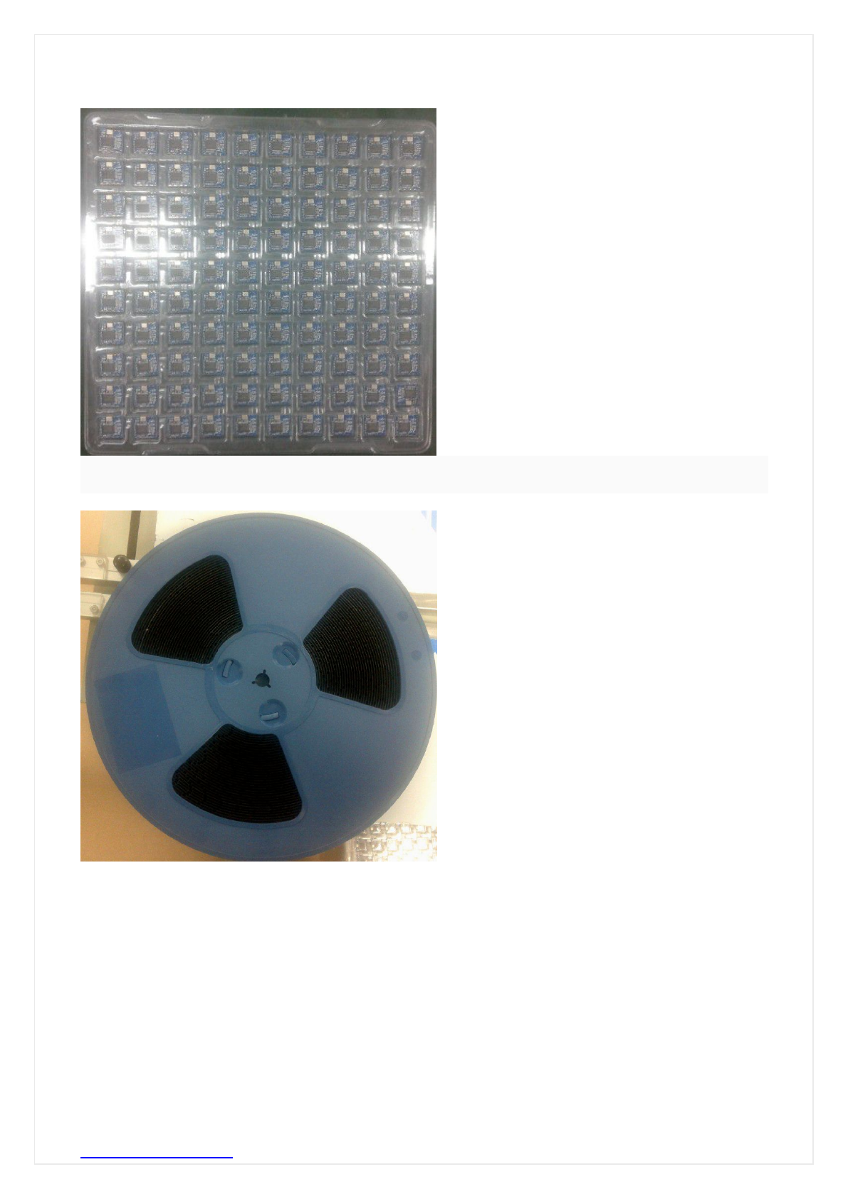
5 PACKING INFORMATION............................................................................................................................. 10
5.1 BLISTER PACKAGING............................................................................................................................. 10
5.2 COILING PACKAGING............................................................................................................................. 10
FN-LINK TECHNOLOGY LIMITED
http://www.fn-link.com Page4/12
1. Introduction
1.1 Overview
F88FTUM13 is a highly integrated and excellent performance Wireless LAN (WLAN) USB2.0
network interface device. High-speed wireless connection up to 150 Mbps.
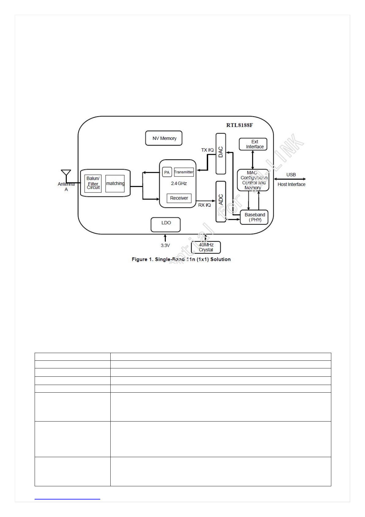
The general hardware for the module is shown in Figure 1. This WLAN Module design is based on
Realtek RTL8188FTV. It is a highly integrated single-chip 1*1 MIMO (Multiple In Multiple Out) Wireless
LAN (WLAN) USB2.0 network interface controller complying with the 802.11n specification. It combines
a MAC, a 1T1R capable baseband, and RF in a single chip. It is designed to provide excellent
performance with low power Consumption and enhance the advantages of robust system and
cost-effective.
1.2 Product Features
Operate at ISM frequency bands (2.4GHz)
USB Interface for WiFi
IEEE standards support: IEEE 802.11b, IEEE 802.11g, IEEE 802.11n,
Enterprise level security which can apply WPA/WPA2 certification for WiFi.
WiFi 1 transmitter and 1 receiver allow data rates supporting up to 150 Mbps downstream and 150
Mbps upstream PHY rates
2. GENERAL SPECIFICATION
2.1 WiFi RF Specifications
Features Descriptions
Main Chipset RTL8188FTV
Frequency Range 2.400~2.4835GHz
Operating Voltage 3.3Vdc ±10% I/O supply voltage
Host Interface WiFi: USB
Standards
WiFi:
IEEE 802.11b,
IEEE 802.11g,
IEEE 802.11n,
Modulation
WiFi:
802.11b(DSSS): CCK(11, 5.5Mbps), DQPSK(2Mbps), DBPSK(1Mbps);
802.11g(OFDM): BPSK(9,6Mbps), QPSK(18,12Mbps),
16QAM(36,24Mbps), 64QAM(54,48Mbps);
802.11n(OFDM): BPSK, QPSK, 16QAM, 64QAM(150Mbps)
PHY Data rates
WiFi:
802.11b: 11,5.5,2,1 Mbps
802.11g: 54,48,36,24,18,12,9,6 Mbps
802.11n: up to 150Mbps

FN-LINK TECHNOLOGY LIMITED
http://www.fn-link.com Page5/12
Transmit Output
Power
WiFi:
802.11b <16dBm
802.11g <14dBm
802.11n <13dBm
EVM
802.11b /11Mbps : EVM≦-9dB
802.11g /54Mbps : EVM≦-25dB
802.11n /65Mbps : EVM≦-28dB
Receiver Sensitivity
802.11b@8% PER
11Mbps -86dBm
802.11g@10% PER
54Mbps -73dBm
802.11n@10% PER
HT20_MCS 7 -70dBm
HT40_MCS 7 -66dBm
Operating Channel
WiFi 2.4GHz:
11: (Ch. 1-11) – United States(North America)
Media Access Control WiFi: CSMA/CA with ACK
Network Architecture
WiFi: Ad-hoc mode (Peer-to-Peer )
Infrastructure mode
Software AP
WiFi Direct
Security WiFi: WPA, WPA-PSK, WPA2, WPA2-PSK, WEP, AES, TKIP
Antenna Integral
OS Supported Android /Linux/ Win CE /iOS /XP/WIN7
Dimension Typical L12.90*W12.20*H1.6mm
2.2 Power Consumption
Power Consumption
(Typical by using
SWR)
WiFi only:
TX Mode: (Continuous mode) 185mA
RX Mode: (Continuous mode) 145mA
LINK:140mA
DISABLE:40mA
(1dBi Max)
FN-LINK TECHNOLOGY LIMITED
http://www.fn-link.com Page7/12
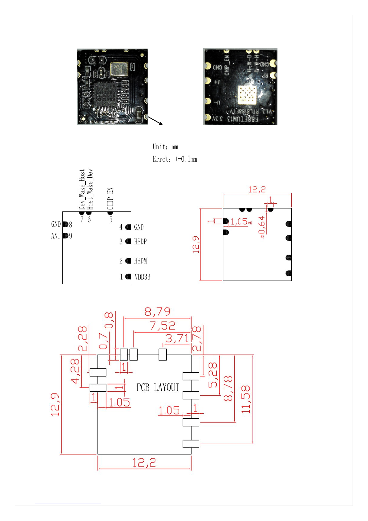
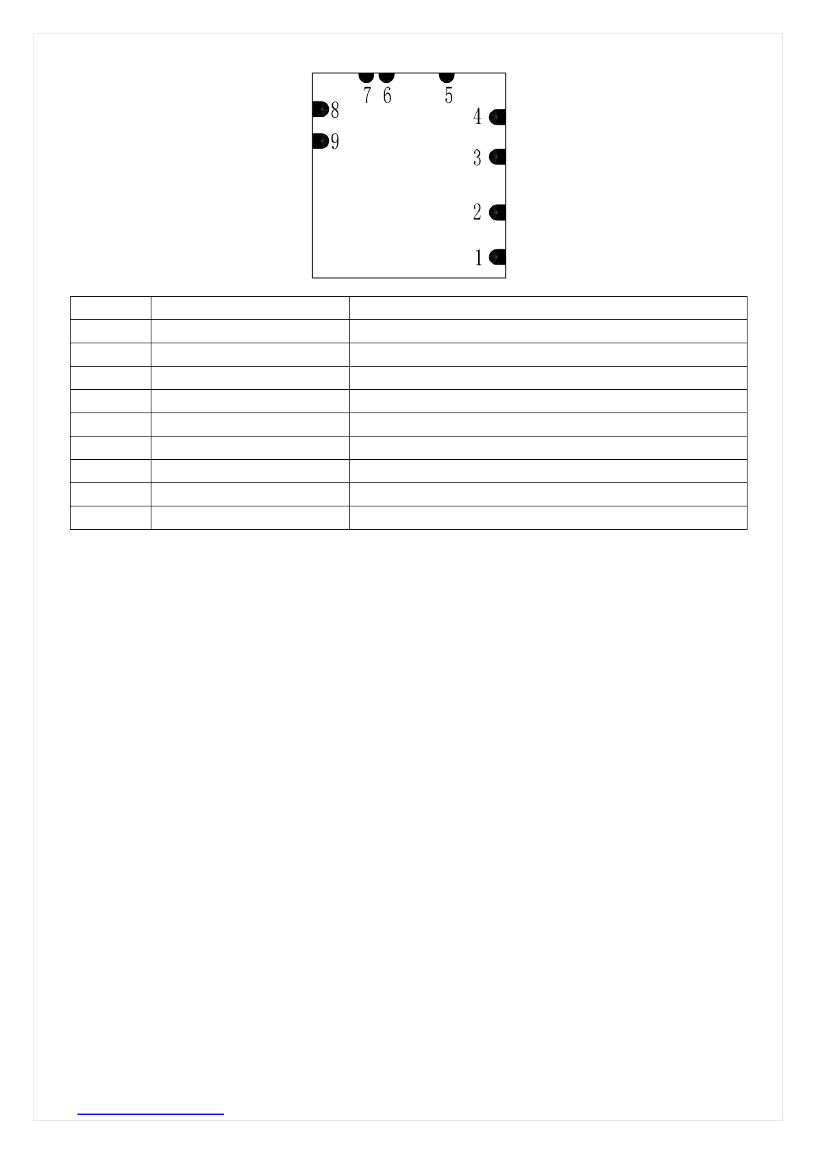
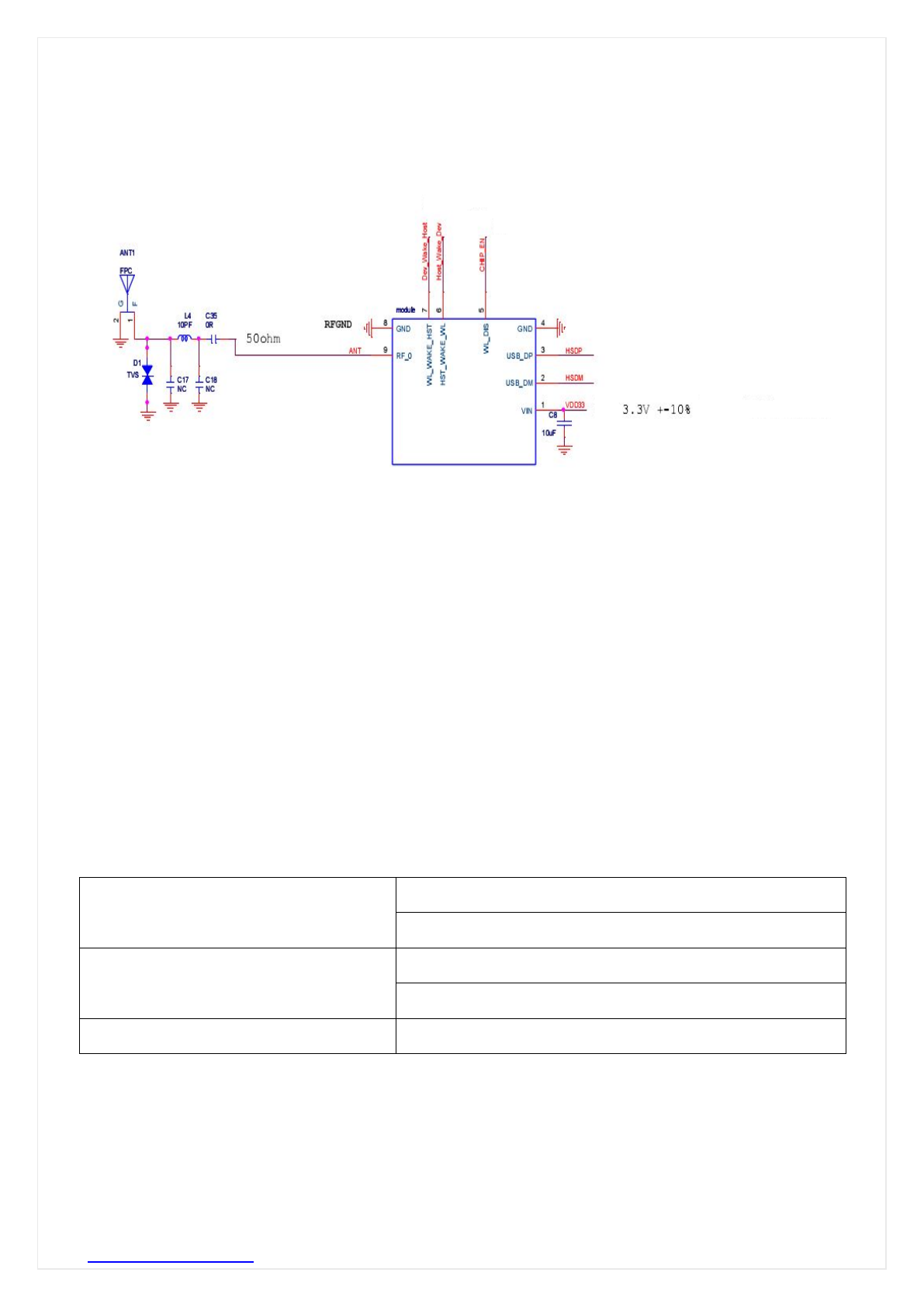
3.2 PIN Assignment
Pin # Name Description
1VDD33 3.3V DC power supply input
2HSDM USB DATA-
3HSDP USB DATA+
4GND Ground
5CHIP_EN This Pin Can Externally Shutdown RTL8188FTV
6Host_Wake_Dev Host Wake Device Input Pin
7Dev_Wake_Host Device Wake Host Output Pin
8GND RF GROUND
9ANT External Antenna (2.4GHz 50Ohm )
FN-LINK TECHNOLOGY LIMITED
http://www.fn-link.com Page8/12
3.3 Application Circuit
4. Environmental Requirements
4.1 Operating& Storage Conditions
Operating
Temperature: 0°C to +70°C
Relative Humidity: 10-90% (non-condensing)
Storage
Temperature: -40°C to +80°C (non-operating)
Relative Humidity: 5-90% (non-condensing)
MTBF (Mean Time Between Failures) Over 150,000hours
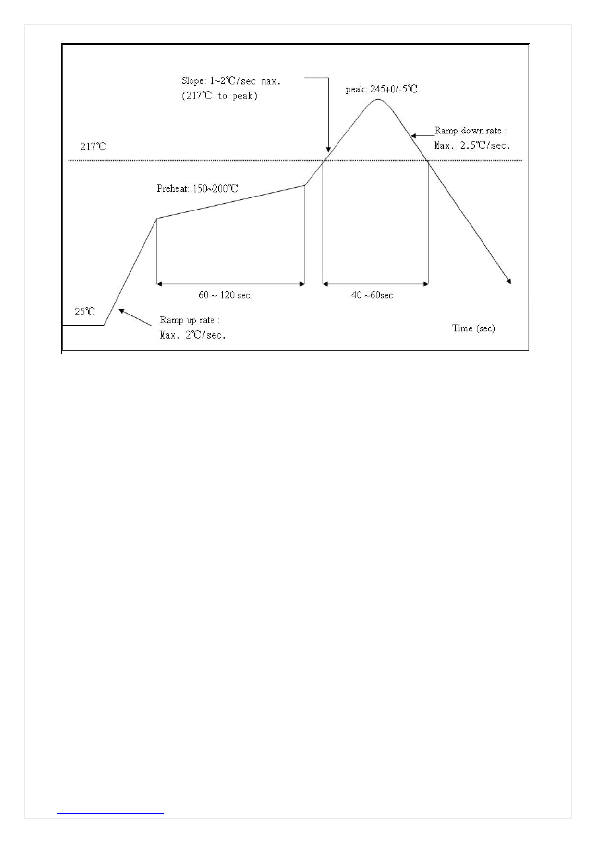
4.2 Recommended Reflow Profile
Referred to IPC/JEDEC standard.
Peak Temperature : <250°C
Number of Times : ≤2 times
FN-LINK TECHNOLOGY LIMITED
http://www.fn-link.com Page9/12
4.3 Patch WIFI modules installed before the notice:
WIFI module installed note:
1. Please press 1 : 1 and then expand outward proportion to 0.7 mm, 0.12 mm thickness When open a
stencil
2. Take and use the WIFI module, please insure the electrostatic protective measures.
3. Reflow soldering temperature should be according to the customer the main size of the products, such
as the temperature set at 250 + 5 ℃for the MID motherboard.
About the module packaging, storage and use of matters needing attention are as follows:
1. The module of the reel and storage life of vacuum packing: 1). Shelf life: 8 months, storage
environment conditions: temperature in: < 40 ℃, relative humidity: < 90% r.h.
2. The module vacuum packing once opened, time limit of the assembly:
Card: 1) check the humidity display value should be less than 30% (in blue), such as: 30% ~ 40% (pink),
or greater than 40% (red) the module have been moisture absorption.
2.) factory environmental temperature humidity control: ≦30% ℃,≦60% r.h..
3). Once opened, the workshop the preservation of life for 168 hours.
3. Once opened, such as when not used up within 168 hours:
1). The module must be again to remove the module moisture absorption.
2). The baking temperature: 125 ℃, 8 hours.
3.) After baking, put the right amount of desiccant to seal packages.
2AATL-F88FTUM13
FN-LINK TECHNOLOGY LIMITED
http://www.fn-link.com Page11/12
1
The module will be responsible to satisfy SAR/RF Exposure requirements, when the module integrated
into any (portable, mobile, fixed) host device.

FN-LINK TECHNOLOGY LIMITED
http://www.fn-link.com Page12/12
This devic has been evaluated and shown compliant with the FCC RF Exposure limits under fixed
exposure conditions (antennas are greater than 20cm from a person's body) when installed in certain
specific OEM configurations.
FCC Radiation Exposure Statement:
This modular complies with FCC RF radiation exposure limits set forth for an uncontrolled environment.
This transmitter must not be co-located or operating in conjunction with any other antenna or transmitter.
Due to missing shielding the module is strictly limited to integration by the Grantee himself or his dedicated
OEM integrator under control of the Grantee.However, the OEM integrator is still responsible for testing
their end-product for any additional compliance requirements required with this module installed.
Note 1: The wifi module has no shielding and tested stand alone.
This module is tested and approved as Limited modular approval with stand alone configuration, any OEM
incorporated this radio module into any system are require additional testing and evaluation.
Note 2: The module is only certified with the installed antenna. Any change of the antenna
will void the certification. The host device including this RF module need to undergo separate
cetification.
Attention:LimitedModularApproval‐thisRFModulemaynotbesoldtothegenericpublic
andrequiresprofessionalinstallation.
DuetothefactthatthisRFModuleisnotequippedwithanownshielding,theend‐product
incl.thisRFModulehastoshowcompliancetotheFCCrules(15C/radiatedemissions).
(OEM)Integratorhastoassurecomplianceoftheentireend‐product
incl.theintegratedRFModule.Additionalmeasurements(15C)and/orequipmentauthorizations
(e.g
mayneedtobeaddresseddependingonco‐locationorsimultaenous
transmissionissuesifapplicable.
Integratorisremindedtoassurethattheseinstallationinstructions
willnotbemadeavailabletotheend‐userofthefinalhostdevice.
integratedintoany(portable,mobile,fixed)hostdevice.
Thefinalhostdevice,intowhichthisRFModuleisintegrated"hastobelabelled
withanauxilliarylablestatingtheFCCIDoftheRFModule,suchas
"ContainsFCCID:
Dependingonthesizeofthefinalend‐product,the§15.19FCCstatement
"Thisdevicecomplieswithpart15oftheFCCrules.Operationissubjecttothefollowingtwo
conditions:
(1)thisdevicemaynotcauseharmfulinterference,and
(2)thisdevicemustacceptanyinterferencereceived,including
interferencethatmaycauseundesiredoperation."
shouldbeplacedalsoonthedeviceoralternativelywithinaprominentlocationoftheusers
manual
The§15.21"Changes or modifications to this unit not expressly
approvedbythepartyresponsibleforcompliancecould
voidtheuser’sauthoritytooperatetheequipment."statementhastobeincludedinaprominent
locationoftheusersmanual
"
)
either a complete new certification or a Class II Permissive Change.
the Integrator will be responsible to satisfy SAR/ RF Exposure requirements,
when the module
2AATL-F88FTUM13

