HUNG WAI DTEX-PS-M Product Selector Master Device User Manual
HUNG WAI PRODUCTS LIMITED Product Selector Master Device
UserManual.wiki
>
HUNG WAI
>
DTEX PS M User Manual
User manual
Navigation menu
Upload a User Manual
Namespaces
Wiki Guide
HTML
PDF
Info
Views
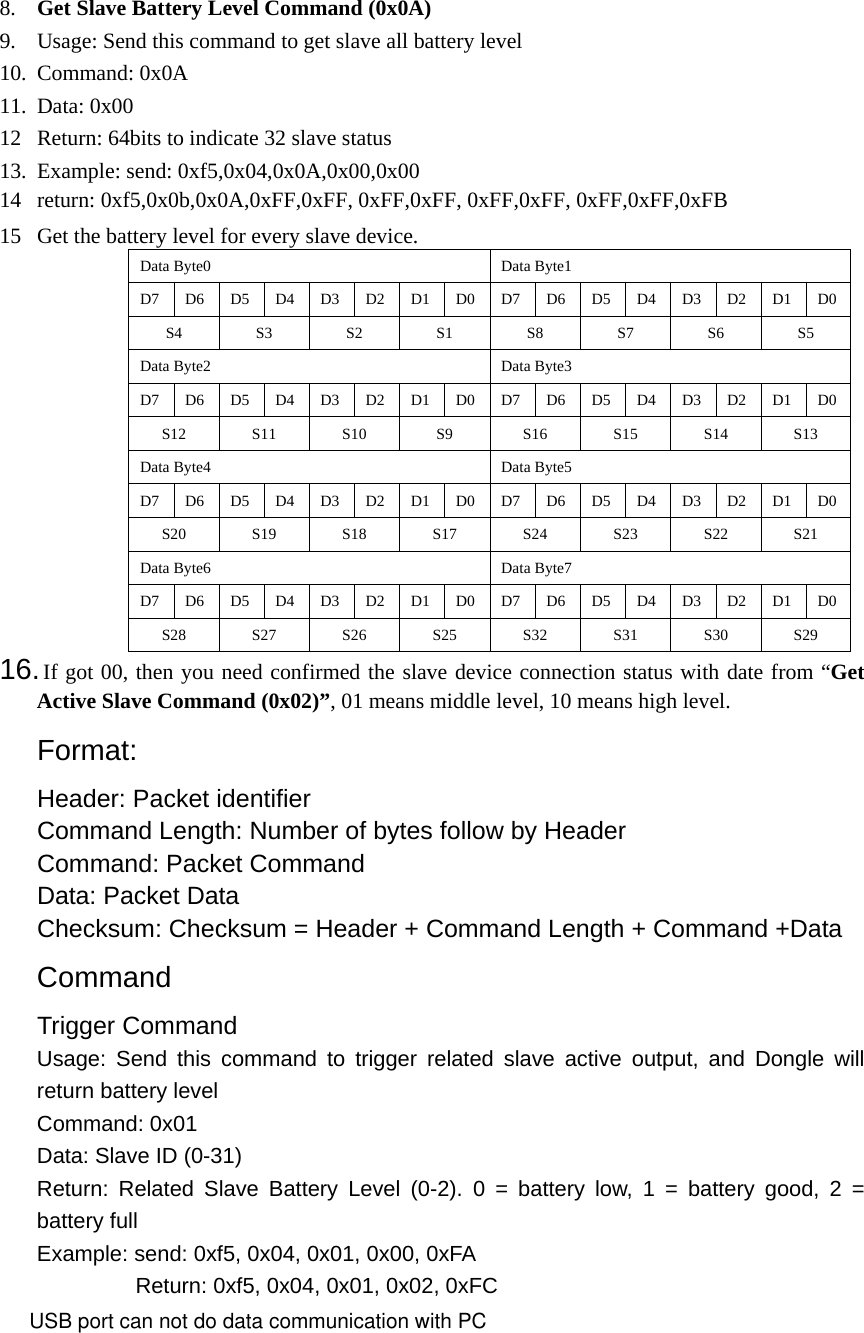
User Manual
Discussion / Help
Navigation