HUNG WAI DTEX-PS-M Product Selector Master Device User Manual
HUNG WAI PRODUCTS LIMITED Product Selector Master Device
HUNG WAI >
User manual
Specification for Product Selector V1.2
1. USB connector or 4pin 2.0 connector: connect to Media Player or
other unit to communicate with each other, also can get the power
from this connector(Just Host Device, and the protocol please see
point 9)
2. Pairing Key and Pairing Indicator: Pairing Key is used to pair the
host device and slave device, right now one host device can pair
with up to 32 pcs slave devices with ID from 1 to 32. Pairing
Indicator can indicate if the device is working on pairing mode and
success for pairing
Pairing: 2.1. Set the host mode and slave mode on the device
according to the below information(Point 6)
2.2. Press and hold th e Pairing Key, and then power on,
after 5 seconds, the Pairing Indicator will flash to indicate the
device are working in pairing mode
2.3. Setting the slav e device to pairing mode one by one
and then setting the host device to pairing mode.
2.4. After pairing succe ss, the Pairing Indicator will be on
2.5. After all the de vice pairing success, power off the
devices or wait 20seconds for auto reset.
3. Reset Key: Reset the system
4. Mode and ID setting switch:
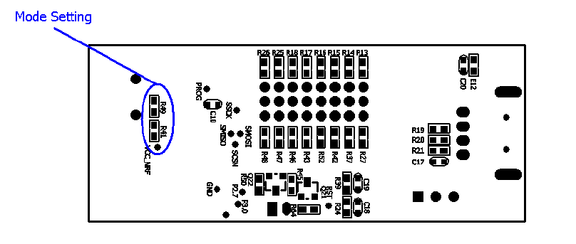
Host/Slave mode setting: There are two resistors for Host or Slave
mode setting. Shown as the pictures below:
When R41 is connected, the device is working on Host Mode;
and when R49 is connected, the device is working in Slave
mode.
When in host mode, there is a pin setting to set the bit rate to
9600bps or 19200bps. We used ID1 for this setting. When
ID1 is short, the bit rate is set to 19200bps, and when ID1 is
open, the bit rate is set to 9600bps.
When in host mode, there is 3 pin setting (ID4, 5, 6) to set
the quantity of slave device. When ID4 is short, the host
support to 8 pcs slave device; and when ID5 is short, the
host device support to 16 pcs slave device; when ID4 & 5 are
short, the host device support to 24 pcs slave device; and
when ID6 is short, the host device support to 32 pcs salve
device.
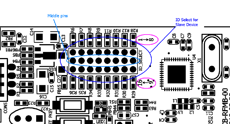
When device is working in Slave mode, the 8x3 jumper connector
is used for ID setting. As the picture below showed:
In the new device, we have change the ID setting mode. The ID
setting was divided to single digit and tens digit.
1-5 and 12-16, total 10 pins have changed to the single digit (1-1,
2-2, 3-3, 4-4, 5-5, 12-6, 13-7, 14-8,15-9, 16-10, none-0); and 6-8,
total 3pins have changed to tens digit (6-10, 7-20, 8-30).
When set the slave ID, we need to short the single digit and/or tens
digit.
Such as if we set the slave ID as ID9, then we need short the
current pin 15. If we set the salve ID as ID10, then we need short
the pin 16 (or short pin 6). If we set the salve ID as ID20,then we
need short the pin 7 (or short pin 6 and pin 16); If we set the slave
ID as ID32, then we need short the pin 8 and pin 2.
5. Push Button switch for output: this switch is just used on the slave
device, for a switch signal which can trigger other device as our
Media players, Audio box and etc.
6. LED Indicator for Slave device: When the module is setting for
slave, this LEDs indicator will be off in standby, if Slave device N
receive a command from the Host device, LED Indicator N will be
on for 1second and PB switch for output will trigger as a push
button function.
7. The host device can communicate with other device through UART
protocol:
UART Protocol V3.2(Add descriptions for the command)
Interface
UART 9600bps 8N1
Command Length: Number of bytes follow by Header
Command: Packet Command
Data: Packet Data Checksum:
Checksum=Header+Command Length+Command+Data
Command Trigger Command
Active Slave Command (0x01)
Usage: Send this command to trigger related slave active ouput, and Dongle will return battery
level
Command: 0x01
Data: Slave ID (0-15)
Return: Related Slave Battery Level (0-2). 0=battery low, 1=battery good, 2=battery full
Example: send: 0xf5,0x04,0x01,0x00,0xFA
return: 0xf5,0x04,0x01,0x02,0xFC
Get Active Slave Command (0x02)
Usage: Get active wireless slave
Command: 0x02
Return: 32bits to indicate 32slave status
Example: send: 0xf5,0x04,0x02,0x00,0xFB

return: 0xf5,0x07,0x02,0xFF,0xFF,0xFF,0xFF,0xFA
D7 D6 D5 D4 D3 D2 D1 D0
0xf5,0x07,0x02 S7 S6 S5 S4 S3 S2 S1 S0, S15 S14 S13 S12 S11 S10 S9 S8,
S23 S22 S21 S20 S19 S18 S17 S16, S31 S30 S29 S28 S27 S26 S25 S24,
Data Byte0 Data Byte1
D7 D6 D5 D4 D3 D2 D1 D0 D7 D6 D5 D4 D3 D2 D1 D0
S8 S7 S6 S5 S4 S3 S2 S1 S16 S15 S14 S13 S12 S11 S10 S9
Data Byte2 Data Byte3
D7 D6 D5 D4 D3 D2 D1 D0 D7 D6 D5 D4 D3 D2 D1 D0
S24 S23 S22 S21 S20 S19 S18 S17 S32 S31 S30 S29 S28 S27 S26 S25
Get the connection status for the slave device: S1 for Slave Device 1,S2 for Slave
Device 2, ……, S32 for Slave Device 32,0 means didn’t find the device, 1 for find
the device.
Wakeup Command (0x03)
Usage: Send this command to wakeup related slave
Command: 0x03
Data: Slave ID (32bits to indicate 32 slave)+Wakeup Time(0-255sec)
Return: 32bits to indicate 32 slave status
Example: send: 0xf5,0x08,0x03,0x00,0x01,0x00,0x00,0x05,0x04
return: 0xf5,0x07,0x03,0xFF,0xFF, 0xFF,0xFF,0xFB
The first 4bytes means the ID for the Slave Device, The fifth byte means the wake
time for the device. If you want the device wake in the next several seconds, you can
use this command to keep the required device keep waking in the next setting times.
In this setting time, the device will respond the active faster than from sleep mode,
however, the working current will also be bigger than sleep device.

8. Get Slave Battery Level Command (0x0A)
9. Usage: Send this command to get slave all battery level
10. Command: 0x0A
11. Data: 0x00
12 Return: 64bits to indicate 32 slave status
13. Example: send: 0xf5,0x04,0x0A,0x00,0x00
14 return: 0xf5,0x0b,0x0A,0xFF,0xFF, 0xFF,0xFF, 0xFF,0xFF, 0xFF,0xFF,0xFB
15 Get the battery level for every slave device.
Data Byte0 Data Byte1
D7 D6 D5 D4 D3 D2 D1 D0 D7 D6 D5 D4 D3 D2 D1 D0
S4 S3 S2 S1 S8 S7 S6 S5
Data Byte2 Data Byte3
D7 D6 D5 D4 D3 D2 D1 D0 D7 D6 D5 D4 D3 D2 D1 D0
S12 S11 S10 S9 S16 S15 S14 S13
Data Byte4 Data Byte5
D7 D6 D5 D4 D3 D2 D1 D0 D7 D6 D5 D4 D3 D2 D1 D0
S20 S19 S18 S17 S24 S23 S22 S21
Data Byte6 Data Byte7
D7 D6 D5 D4 D3 D2 D1 D0 D7 D6 D5 D4 D3 D2 D1 D0
S28 S27 S26 S25 S32 S31 S30 S29
16.
If got 00, then you need confirmed the slave device connection status with date from “Get
Active Slave Command (0x02)”, 01 means middle level, 10 means high level.
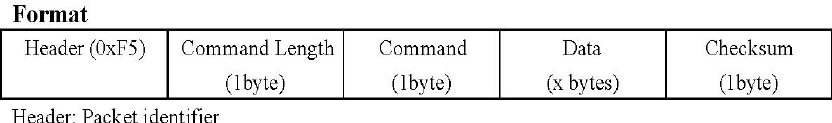
Format:
Header: Packet identifier
Command Length: Number of bytes follow by Header
Command: Packet Command
Data: Packet Data
Checksum: Checksum = Header + Command Length + Command +Data
Command
Trigger Command
Usage: Send this command to trigger related slave active output, and Dongle will
return battery level
Command: 0x01
Data: Slave ID (0-31)
Return: Related Slave Battery Level (0-2). 0 = battery low, 1 = battery good, 2 =
battery full
Example: send: 0xf5, 0x04, 0x01, 0x00, 0xFA
Return: 0xf5, 0x04, 0x01, 0x02, 0xFC
USB port can not do data communication with PC
FCC Statement
1. This device complies with Part 15 of the FCC Rules. Operation is subject to the following two
conditions:
(1) This device may not cause harmful interference.
(2) This device must accept any interference received, including interference that may cause undesired
operation.
2. Changes or modifications not expressly approved by the party responsible for compliance could void
the user's authority to operate the equipment.
NOTE:
This equipment has been tested and found to comply with the limits for a Class B digital device, pursuant
to Part 15 of the FCC Rules. These limits are designed to provide reasonable protection against harmful
interference in a residential installation.
This equipment generates uses and can radiate radio frequency energy and, if not installed and used in
accordance with the instructions, may cause harmful interference to radio communications. However,
there is no guarantee that interference will not occur in a particular installation. If this equipment does
cause harmful interference to radio or television reception, which can be determined by turning the
equipment off and on, the user is encouraged to try to correct the interference by one or more of the
following measures:
Reorient or relocate the receiving antenna.
Increase the separation between the equipment and receiver.
Connect the equipment into an outlet on a circuit different from that to which the receiver is connected.
Consult the dealer or an experienced radio/TV technician for help.