HYT Science and Technology Co TC-580V FM Handheld Transceiver User Manual
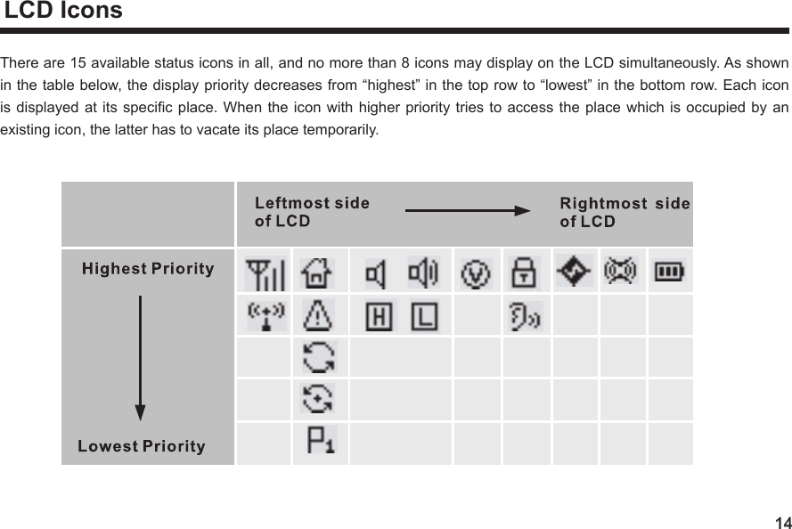
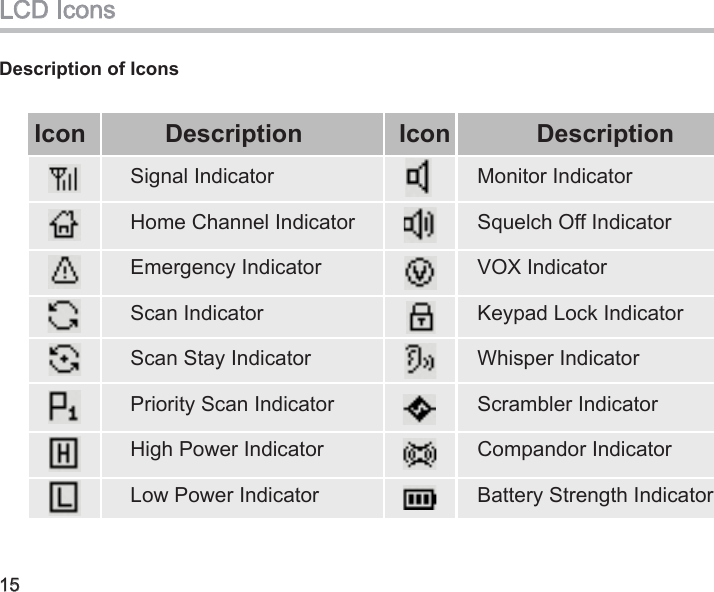
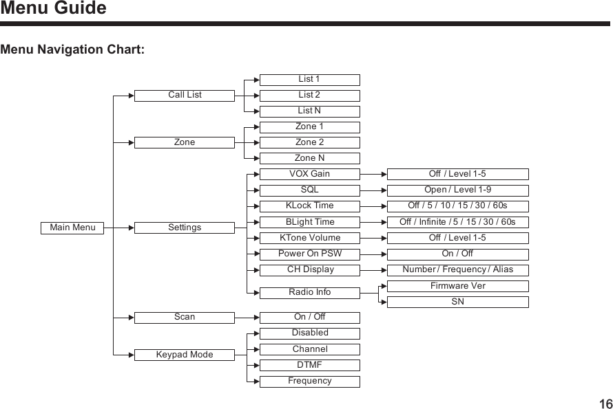
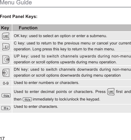
Shenzhen HYT Science &Technology; Co Ltd FM Handheld Transceiver Users Manual
UserManual.wiki
>
HYT Science and Technology Co
>
TC 580V User Manual
Users Manual
Navigation menu
Upload a User Manual
Namespaces
Wiki Guide
HTML
PDF
Info
Views
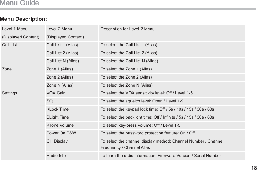
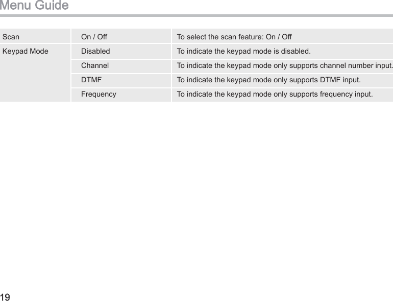
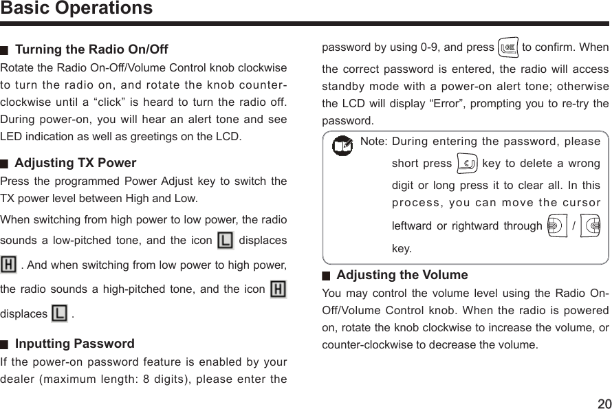
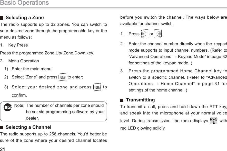
User Manual
Discussion / Help
Navigation