HYT Science and Technology Co TC-580V FM Handheld Transceiver User Manual
Shenzhen HYT Science &Technology; Co Ltd FM Handheld Transceiver Users Manual
Users Manual

1
Preface:
Thank you for purchasing HYT TC-580 Professional Portable Radio.
This easy-to-use radio will deliver you secure, instant and reliable
communication services at peak efciency. Please read this manual
carefully before use. The information presented herein can help you
to derive optimum performance from your radio.

SAFETYTRAINING INFORMATION
Your HYT radio generates RF electromagnetic energy during
transmit mode. This radio is designed for and classified as
“Occupational Use Only”, meaning it must be used only during
the course of employment by individuals aware of the hazards,
and the ways to minimize such hazards. This radio is NOT
intended for use by the “General Population” in an uncontrolled
environment.
This radio has been tested and complies with the FCC RF exposure limits for
“Occupational Use Only”. In addition, your HYT radio complies with the following
Standards and Guidelines with regard to RF energy and electromagnetic energy levels
and evaluation of such levels for exposure to humans:
FCC OET Bulletin 65 Edition 97-01 Supplement C, Evaluating Compliance with FCC
Guidelines for Human Exposure to Radio Frequency Electromagnetic Fields.
American National Standards Institute (C95.1-1992), IEEE Standard for Safety Levels
with Respect to Human Exposure to Radio Frequency Electromagnetic Fields, 3 kHz
to 300 GHz.
American National Standards Institute (C95.3-1992), IEEE Recommended Practice
for the Measurement of Potentially Hazardous Electromagnetic Fields– RF and
Microwave.
The following accessories are authorized for use with this product. Use of accessories
other than those (listed in the instruction) specified may result in RF exposure levels
exceeding the FCC requirements for wireless RF exposure.
To ensure that your expose to RF electromagnetic
energy is within the FCC allowable limits for
occupational use, always adhere to the following
guidelines:
DO NOT operate the radio without a proper antenna attached, as this may damaged
the radio and may also cause you to exceed FCC RF exposure limits. A proper
antenna is the antenna supplied with this radio by the manufacturer or antenna
specifically authorized by the manufacturer for use with this radio.
DO NOT transmits for more than 50% of total radio use time (“50%duty cycle”).
Transmitting more than 50% of the time can cause FCC RF exposure compliance
requirements to be exceeded. The radio is transmitting when the “TX indicator” lights
red. You can cause the radio to transmit by pressing the “PTT” switch.

ALWAYS keep the antenna at least 2.5 cm (1 inch) away from the body when
transmitting and only use the HYT belt-clip which is listed in instructions when
attaching the radio to your belt, etc., to ensure FCC RF exposure compliance
requirements are not exceeded. To provide the recipients of your transmission the
best sound quality, hold the antenna at least 5 cm (2 inches) from your mouth, and
slightly off to one side.
The information listed above provides the user with the information needed to make him
or her aware of RF exposure, and what to do to as-sure that this radio operates with the
FCC RF exposure limits of this radio.
Electromagnetic Interference/Compatibility
During transmissions, your HYT radio generates RF energy that can possibly cause
interference with other devices or systems. To avoid such interference, turn off the radio in
areas where signs are posted to do so. DO NOT operate the transmitter in areas that are
sensitive to electromagnetic radiation such as hospitals, aircraft, and blasting sites.
Occupational/Controlled Use
The radio transmitter is used in situations in which persons are exposed as consequence
of their employment provided those persons are fully aware of the potential for exposure
and can exercise control over their exposure.
IMPORTANT
READ ALL INSTRUCTIONS carefully and completely before using the
transceiver
SAVE THIS INSTRUCTION MANUAL- This instruction manual contains
important operating instructions for the Two-Way Radio
EXPLICIT DEFINITIONS
WORD DEFINITION
WARNING Personal injury, fire hazard or electric shock
may occur.
CAUTION Equipment damage may occur.
NOTE If disregarded, inconvenience only. No risk
of personal injury, fire or electric shock.

OPERATING NOTES
When transmitting with a portable radio, hold the radio in a vertical position with its
microphone 5 to 10 cm (2 to 4 inches) away from your mouth. Keep the antenna at
least 2.5 cm (1 inch) from your head and body.
If you wear a portable two-way radio on your body, ensure that the antenna is at least
2.5 centimeters (1 inch) from your body when transmitting.
PRECAUTIONS
WARNING! NEVER hold the transceiver so that the antenna is very close to, or touching
exposed parts of the body, especially the face or eyes, while transmitting. The transceiver
will perform best if the microphone is 5 to 10 cm (2 to 4 inches) away from the lips and the
transceiver is vertical.
WARNING! NEVER operate the transceiver with a headset or other audio accessories at
high volume levels.
CAUTION! NEVER short the terminals of the battery pack.
NEVER connect the transceiver to a power source other than the Battery listed below
Such a connection will ruin the transceiver.
DO NOT push the PTT when not actually desiring to transmit.
AVOID using or placing the transceiver in direct sunlight or in areas with temperatures
below –30°C (–22°F) or above +60°C (+140°F).
DO NOT modify the transceiver for any reason.
MAKE SURE the flexible antenna and battery pack are securely attached to the
transceiver, and that the antenna and battery pack are dry before attachment. Exposing
the inside of the transceiver to water will result in serious damage to the transceiver.
BE CAREFUL! The series transceivers employ waterproof construction, which
corresponds to IPX7 of the international standard IEC 60529 (2001), 1 m depth for 30
minutes. However, once the transceiver has been dropped, waterproofing cannot be
guaranteed due to the fact that the transceiver may be cracked, or the waterproof seal
damaged, etc.
The use of non-HYT battery packs/chargers may impair transceiver performance and
invalidate the warranty.
FCC CAUTION:
Changes or modifications to this device, not expressly approved by HYT, could void
your authority to operate this transceiver under FCC regulations.
FCC INFORMATION FOR R74TC-580V
This device compliance with Part 90 of the FCC rules. Operation is subject to the
following two conditions: (1) This device may not cause harmful interference, and (2)
This device must except any interference received, including interference that may
cause undesired operation.
FCC ID: R74TC-580V

2
Icon Information
The following icons are available through this manual:
Copyright Information
HYT and CRS are registerred trademarks of HYT in P.R.C and other coutries and/or areas. We retain
the ownership of our own trademarks and products only. All other product names and trademarks
mentioned herein are the property of their respective owners.
Disclaimer
HYT endeavors to achieve the accuracy and completeness of this manual, but no warranty of accuracy
or reliability is given. All the above specications and designs are subject to change without notice due
to continuous development. No part of this manual may be copied, reproduced, translated, stored in a
retrievable system, distributed, or transmitted in any form or by any means, electronic or mechanical,
for any purpose without the express written permission of HYT.
Caution: indicates situations that could cause damage
to your radio.
Note: indicates tips that help you make better use of
your radio.

3
Safety Information --------------------------------------------- 1
Product Inspection --------------------------------------------- 3
Radio Overview ------------------------------------------------ 4
Battery Information -------------------------------------------- 7
Assembly and Disassembly --------------------------------- 11
Attaching/Removing the Battery ------------------------------- 11
Attaching/Removing the Antenna ------------------------------ 12
Attaching/Removing the Belt Clip ------------------------------ 13
Attaching/Removing the External Earpiece/Microphone - 13
LCD Icons-------------------------------------------------------- 14
Menu Guide ----------------------------------------------------- 16
Basic Operations ----------------------------------------------- 20
Turning the Radio On/Off ---------------------------------------- 20
Adjusting TX Power ----------------------------------------------- 20
Inputting Password ------------------------------------------------ 20
Adjusting the Volume --------------------------------------------- 20
Selecting a Zone --------------------------------------------------- 21
Selecting a Channel ----------------------------------------------- 21
Transmitting --------------------------------------------------------- 21
Receiving ------------------------------------------------------------ 22
Programmable Auxiliary Functions ------------------------ 23
Advanced Operations ----------------------------------------- 24
CTCSS/CDCSS ---------------------------------------------------- 24
DTMF ----------------------------------------------------------------- 24
Channel Scan ------------------------------------------------------- 26
Emergency ---------------------------------------------------------- 29
Time-out Timer (TOT) --------------------------------------------- 29
Battery Save -------------------------------------------------------- 30
Compandor ---------------------------------------------------------- 31
Display Mode Switch ---------------------------------------------- 31
Home Channel------------------------------------------------------ 31
Keypad Mode ------------------------------------------------------- 32
Monitor---------------------------------------------------------------- 33
Monitor Momentary ------------------------------------------------ 33
Scrambler ------------------------------------------------------------ 33
Squelch Off ---------------------------------------------------------- 34
Squelch Off Momentary ------------------------------------------ 34
Voice-operated Transmit (VOX) -------------------------------- 34
Whisper--------------------------------------------------------------- 35
Reverse Display ---------------------------------------------------- 36
Troubleshooting ------------------------------------------------ 37
Care and Cleaning -------------------------------------------- 39
Optional Accessories ----------------------------------------- 40
Contents

1
Safety Information
We would like to extend our sincere thanks for your in-
terest in HYT products. To help you ward off bodily injury
and property loss resulting from improper operation,
please read all safety information in this manual care-
fully.
Rules on Applicable Environments
1. In a location with fuel, chemicals, explosive
atmospheres and other flammable/explosive
materials, only approved Ex-protection radios are
allowed for use;
2. Turn off your radio before entering a blasting area;
3. Turn off your radio before boarding an aircraft;
4. Do not operate your radio near any medical or
electronic device that is vulnerable to RF signals;
5. Do not operate your radio in any area where use of
wireless communication equipment is completely
prohibited to avoid potential electromagnetic
interference and/or compatibility conicts.
Operating Instructions
1. Please only use accessories approved by HYT.
Unauthorized use of other accessories may result in
bodily injury and property loss due to compatibility
conict;
2. For your health, make sure the antenna is at least 2.5
cm away from your body;
3. Do not use any portable radio that has a damaged
antenna. A minor burn may result if the damaged
antenna comes into contact with your skin;
4. Please operate your radio at specied temperature
range; otherwise, it may suffer physical damage or
performance reduction;
5. Continuous transmission for a long time may
lead to heat accumulation within its body. In this
case, please keep your radio at a proper location
for cooling to avoid potential damage by high
temperature;
2
6. Exposure to high-level volume for a long time may
pose hazards to your hearing capability, so be sure
to select the right volume level;
7. Do not operate a portable radio while driving to
ensure your safety. When such operation is a must,
please park your vehicle at a proper place rst;
8. For vehicles with an air bag, do not place a radio
over an air bag or in the air bag deployment area.
Air bags inate with great force, which may impulse
the radio and cause serious injury to occupants of
the vehicle;
9. Avoid operating the radio with a wet hand to derive
the optimal performance;
10. Operate the radio key and keypad with proper force
to prolong their lifespan; clean them with soft brush
on a regular basis for the accumulated dust and dirt
may disable normal use;
11. Users wearing a pacemaker, a hearing aid or other
medical devices shall abide by the following rules:
Make sure the radio is at least 20 cm away from
your medical device during power-on;
Receive signals at a farther place from your
medical device. This can help reduce potential
interference;
When your medical device can not work normally
due to radio interference, turn off your radio
immediately and consult the manufacturer of
medical device for help;
12. Do not expose the radio to direct sunlight for a long
time or place it close to other heating sources,
which may cause performance reduction;
13. Do not disassemble, modify or repair your radio for
any reason, which may result in function failure or
even explosion hazards in the blasting area;
14. To avoid any potential hazard, keep your radio and
its accessories out of the reach of your children and
pets.
Safety Information
3
Item
Li-Ion Battery
Rapid-Rate Charger
Switching Power
Belt Clip
Strap
Antenna
Owner’s Manual
Qty. (PCS)
1
1
1
1
1
1
1
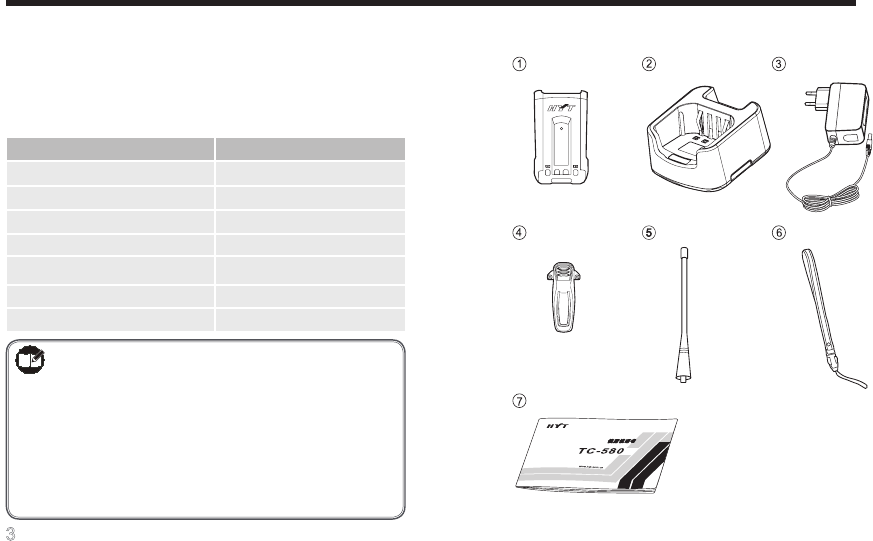
Product Inspection
Before using this radio, please unpack the package box
carefully and check that all shipped items are received;
report any missing or damaged items to your dealer.
Accessories supplied with the radio:
Note:
1) The pictures are for reference only.
2) The antenna may vary with different
frequency bands. And the frequency band
is marked on the label of antenna; if not,
please refer to the label on the radio unit
for frequency band information.
Li-Ion Battery Rapid-Rate Charger Switching Power
Belt Clip Antenna Strap
Owner's Manual
4
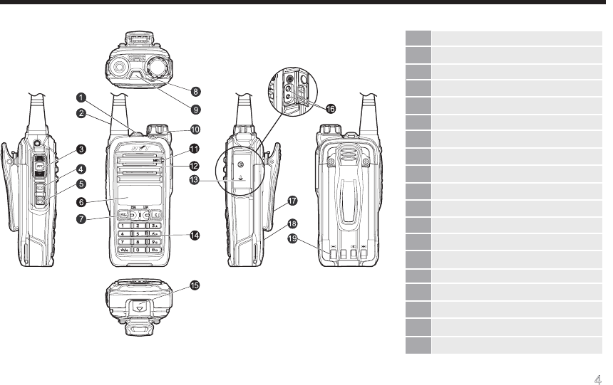
Radio Overview
(1) Strap Hole
(2) Antenna
(3) PTT (Push-to-Talk) Key
(4) SK1 (programmable)
(5) SK2 (programmable)
(6) LCD Display
(7) Function Keypad
(8) LED Indicator
(9) TK (programmable)
(10) Radio On-Off/Volume Control Knob
(11) Microphone
(12) Speaker
(13) Accessory Jack Cover
(14) Numeric Keypad
(15) Battery Latch
(16) Accessory Jack
(17) Belt Clip
(18) Battery
(19) Charging Piece
5
PTT (Push-to-Talk) Key
Press and hold down the PTT key to transmit, and
release it to receive.
SK1/ SK2/ TK
Used to be programmed with auxiliary functions (long or
short press) by your dealer.
LCD Display
Used to display information about radio operation.
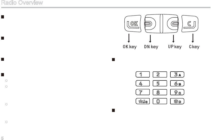
Function Keypad
OK key: to access a menu or to select an option.
DN key: to switch channels downwards during
non-menu operation or to scroll options
downwards during menu operation.
UP key: to switch channels upwards during non-
menu operation or to scroll options upwards
during menu operation.
C key: to return to the previous menu. Long press
this key to return to the main menu.
Numeric Keypad
Used to enter information for programming the radio.
Radio On-Off/Volume Control Knob
Used to turn the radio on/off, and to adjust the volume.
Radio Overview
6
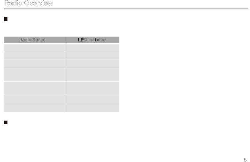
LED Indicator
Descriptions of LED indicator are as follows:
Accessory Jack
Used to connect accessories such as an earpiece, or a
programming cable for radio programming or software
upgrade.
Radio Status LED Indicator
Transmitting
Receiving
Low battery alert
When a call is transmitted
(within the Auto Reset Time)
When a call is received (within
the Auto Reset Time)
Missed call alert
Scanning
Solidly glows red
Solidly glows green
Flashes red
Solidly glows orange.
Slowly ashes orange
Rapidly ashes orange
Flashes green
Radio Overview

7
Battery Information
Operating Instructions
1. Please only use the battery approved by HYT;
unauthorized use of other batteries may result in
explosion and re hazards;
2. Do not remove and replace the battery in explosive
areas to avoid explosion, re and other hazards;
3. Do not discard the battery in re which may lead to
explosion, re and other hazards;
4. Do not expose the battery to direct sunlight for a
long time or place it close to other heating sources,
which may cause performance reduction even re/
explosion hazard;
5. Separate the battery from other metal parts to avoid
potential hazards resulting from short circuit;
6. Do not squeeze or penetrate the battery to prevent
potential battery leakage causing damage to other
people or to our living environment;
7. Do not treat the worn battery as household garbage.
Recycling of the battery shall comply with your local
laws and regulations.
Charging Instructions
1. New batteries shipped from the factory are partially
charged. Three complete charge-discharge cycles
would optimize the capacity and performance of
your battery;
2. Do not charge your battery in an area with explosive
hazards. Please only use the charger approved by
HYT;
3. Charge the battery at a temperature of 5℃-40℃.
Violation of the said limit may result in the battery
not being fully charged or even battery damage;
4. To charge the battery attached to a radio, turn off
the radio to ensure a full charge;
5. Do not charge a battery that is wet. Please dry it
with soft cloth prior to charge to avoid electric shock,
short circuit and other hazards;

8
Battery Information
6. Do not remove the battery or unplug the power
cable during charging to ensure a smooth charging
process;
7. Overcharge shall always be prohibited for it may
shorten the normal life of your battery.
Maintenance Instructions
1. Battery performance will go down when the ambient
temperature is below 0oC, so a spare battery is
necessary in cold weather;
2. Accumulated dust on charging piece may cause the
battery to work or charge abnormally. Please use a
clean and dry cloth to wipe it when necessary;
3. Batteries would gradually self-discharge. Therefore,
please fully charge the battery to be stored for a
long time; then wrap it up with a plastic bag and
keep it in a dry and cool place. This can provide
defense against moisture intrusion and any damage
caused by over self-discharge.
4. To avoid battery capacity reduction due to over self-
discharge, recharge the battery fully after storing it
for a certain period of time (approximately 3 months
for Ni-MH batteries and 6 months for Li-Ion & Li-
polymer batteries);
5. Prevent the battery from dropping down to the
ground or colliding with other objects; otherwise, the
battery performance will degrade signicantly;
6. Recharge the battery only when its power is
exhausted. This is helpful to prolong its life.
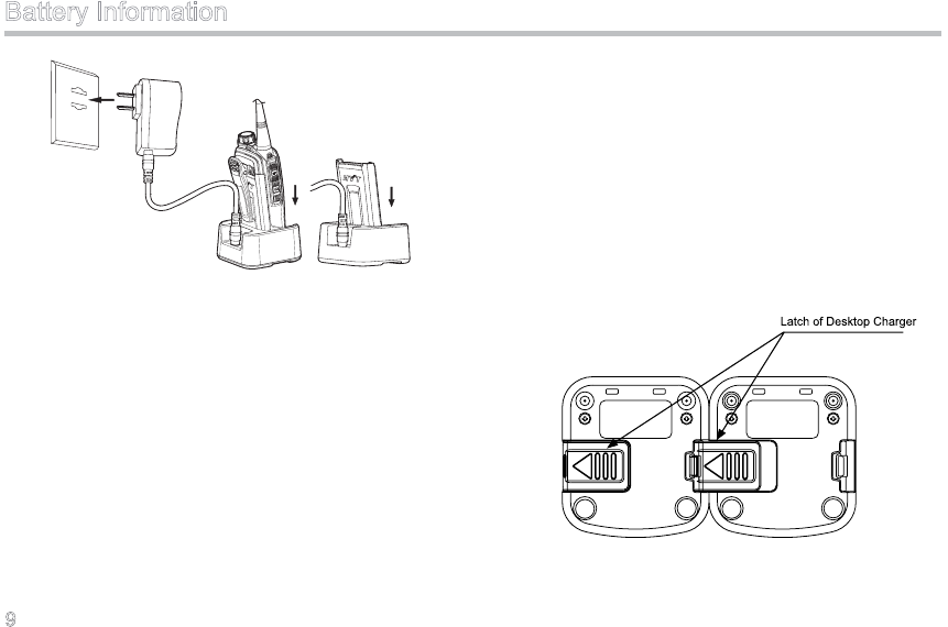
Charging the Battery
Use only the chargers specified by HYT. See figures
below for detailed charging methods:
Charging Method I
9
Battery Information
Please follow the steps below to charge your battery:
1. Plug the AC connector of the adapter into the AC
outlet socket.
2. Plug the DC connector of the adapter into the DC
socket on back of the charger. And the charger LED
solidly glows green.
3. Place the radio with the battery attached, or the
battery alone, into the charger.
4. Make sure that the battery is in good contact with
the charging terminals. The charging process begins
when the charger LED solidly glows red.
5. When charging is completed, the charger LED
solidly glows green (when charging is about to be
completed, the LED glows orange). Then remove
the battery or the radio from the charger.
Charging Method II
You may connect multiple desktop charges in parallel to
create a multi-unit charger. Assembly Method: Slide the
latch of a charger into the slot on the bottom of another
charger, as shown in Figure 1.
Figure 1 Diagram of Multi-Unit Charger Assembly
10
Battery Information
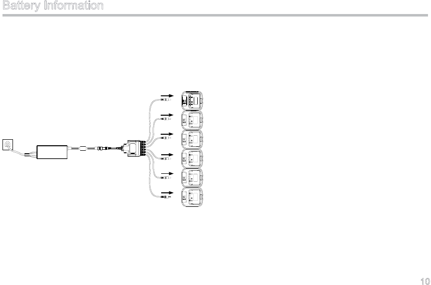
You can use HYT Six-Unit Switching Power to charge up
to six batteries assembled as above simultaneously, as
shown in Figure 2. Please refer to the Owner’s Manual
for Six-Unit Switching Power for detailed operation
instructions.
Figure 2 Schematic Diagram of Six-Unit Charger
11
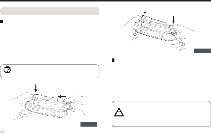
Assembly and Disassembly
Attaching/Removing the Battery
Attaching the Battery
1. Press the belt clip, and push the battery into the
radio’s slot;
2. Press the battery bottom gently until a click is heard,
which indicates that the battery is properly attached
to the radio.
Figure 1
Note:If the battery is loose or unsecured,
please remove and attach it again.
Figure 2
Removing the Battery
1. Turn off the radio rst.
2. Press the belt clip, and lift the battery latch in the
direction as shown below;
3. When the battery bottom gets tilted, release the
latch and remove the battery.
Caution: Make sure the battery bottom is
slightly tilted to avoid severe abrasions
between the battery tab and the slot in the
top part of the radio.
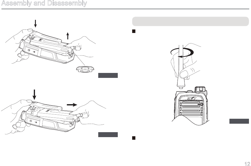
12
Assembly and Disassembly
Figure 3
Figure 4
Attaching/Removing the Antenna
Attaching the Antenna
Turn the antenna clockwise to fasten it.
Figure 5
Removing the Antenna
Turn the antenna counter-clockwise to remove it.
13
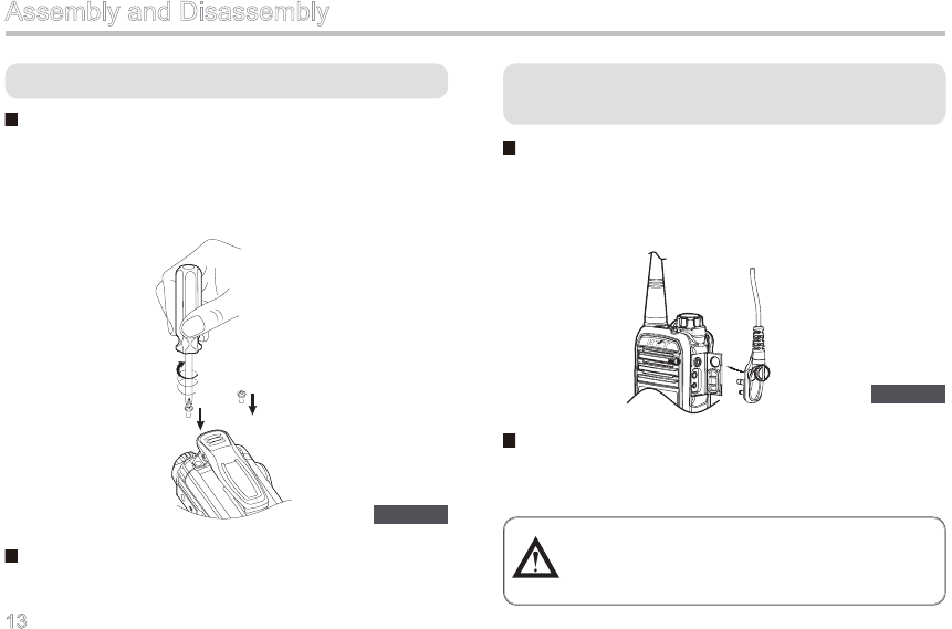
Attaching/Removing the Belt Clip
Attaching the Belt Clip
1. Loosen and remove the screws for belt clip;
2. Align the screw holes in the belt clip with those on the
radio body. And then use a screwdriver to secure the
screws as shown below.
Figure 6
Assembly and Disassembly
Attaching/Removing the External Earpiece/
Microphone
Attaching the External Earpiece/Microphone
1. Uncover (not remove) the accessory jack cover;
2. Insert the earpiece/microphone plug into the jack,
and secure the screw.
Removing the External Earpiece/Microphone
Unfasten the screw and unplug the external earpiece/
microphone.
Figure 7
Caution: When you are using the external
earpiece/microphone, waterproof
performance of the radio may get affected.
Removing the Belt Clip
Unfasten the screws and remove the belt clip.
14
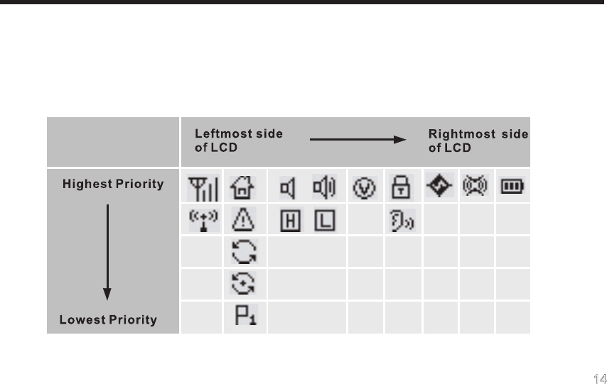
LCD Icons
There are 15 available status icons in all, and no more than 8 icons may display on the LCD simultaneously. As shown
in the table below, the display priority decreases from “highest” in the top row to “lowest” in the bottom row. Each icon
is displayed at its specic place. When the icon with higher priority tries to access the place which is occupied by an
existing icon, the latter has to vacate its place temporarily.
15
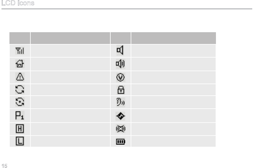
LCD Icons
Description of Icons
Icon Description
Signal Indicator
Home Channel Indicator
Emergency Indicator
Scan Indicator
Scan Stay Indicator
Priority Scan Indicator
High Power Indicator
Low Power Indicator
Monitor Indicator
Squelch Off Indicator
VOX Indicator
Keypad Lock Indicator
Whisper Indicator
Scrambler Indicator
Compandor Indicator
Battery Strength Indicator
Icon Description
16
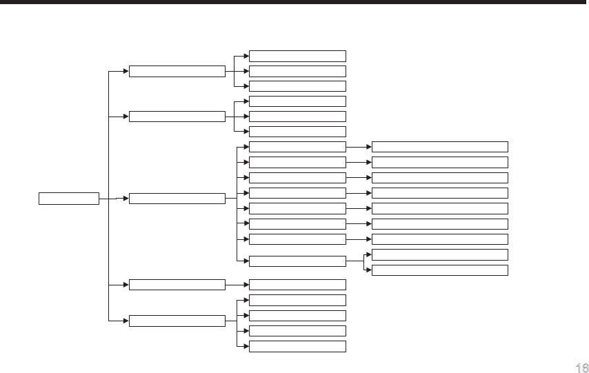
Menu Guide
Menu Navigation Chart:
Zone
1
Zone
2
Zone
N
Zone
VOX Gain
SQL
KLock Time
BLight
Time
KTone Volume
Power On PSW
CH
Display
Radio Info
On / Off
Settings
Disabled
Scan
Channel
DTMF
Frequency
Keypad Mode
Main Menu
Off / Level 1-5
Open
/ Level 1-9
Off / 5 / 10 / 15 / 30 / 60s
Off / Infinite / 5 / 15
/ 30 / 60s
Off / Level 1-5
On / Off
Number / Frequency / Alias
Firmware Ver
SN
List N
List 2
List 1
Call
List
17
Menu Guide
Key Function
OK key: used to select an option or enter a submenu.
C key: used to return to the previous menu or cancel your current
operation. Long press this key to return to the main menu.
UP key: used to switch channels upwards during non-menu
operation or scroll options upwards during menu operation.
DN key: used to switch channels downwards during non-menu
operation or scroll options downwards during menu operation
Used to enter numbers or characters.
Used to enter decimal points or characters. Press first and
then immediately to lock/unlock the keypad.
Used to enter characters.
0-9
Front Panel Keys:

18
Level-1 Menu Level-2 Menu Description for Level-2 Menu
(Displayed Content) (Displayed Content)
Call List Call List 1 (Alias) To select the Call List 1 (Alias)
Call List 2 (Alias) To select the Call List 2 (Alias)
Call List N (Alias) To select the Call List N (Alias)
Zone Zone 1 (Alias) To select the Zone 1 (Alias)
Zone 2 (Alias) To select the Zone 2 (Alias)
Zone N (Alias) To select the Zone N (Alias)
Settings VOX Gain To select the VOX sensitivity level: Off / Level 1-5
SQL To select the squelch level: Open / Level 1-9
KLock Time To select the keypad lock time: Off / 5s / 10s / 15s / 30s / 60s
BLight Time To select the backlight time: Off / Innite / 5s / 15s / 30s / 60s
KTone Volume To select key-press volume: Off / Level 1-5
Power On PSW To select the password protection feature: On / Off
CH Display To select the channel display method: Channel Number / Channel
Frequency / Channel Alias
Radio Info To learn the radio information: Firmware Version / Serial Number
Menu Guide
Menu Description:

19
Scan On / Off To select the scan feature: On / Off
Keypad Mode Disabled To indicate the keypad mode is disabled.
Channel To indicate the keypad mode only supports channel number input.
DTMF To indicate the keypad mode only supports DTMF input.
Frequency To indicate the keypad mode only supports frequency input.
Menu Guide
20
Turning the Radio On/Off
Rotate the Radio On-Off/Volume Control knob clockwise
to turn the radio on, and rotate the knob counter-
clockwise until a “click” is heard to turn the radio off.
During power-on, you will hear an alert tone and see
LED indication as well as greetings on the LCD.
Adjusting TX Power
Press the programmed Power Adjust key to switch the
TX power level between High and Low.
When switching from high power to low power, the radio
sounds a low-pitched tone, and the icon displaces
. And when switching from low power to high power,
the radio sounds a high-pitched tone, and the icon
displaces .
Inputting Password
If the power-on password feature is enabled by your
dealer (maximum length: 8 digits), please enter the
Basic Operations
password by using 0-9, and press to conrm. When
the correct password is entered, the radio will access
standby mode with a power-on alert tone; otherwise
the LCD will display “Error”, prompting you to re-try the
password.
Adjusting the Volume
You may control the volume level using the Radio On-
Off/Volume Control knob. When the radio is powered
on, rotate the knob clockwise to increase the volume, or
counter-clockwise to decrease the volume.
Note: During entering the password, please
short press key to delete a wrong
digit or long press it to clear all. In this
process, you can move the cursor
leftward or rightward through /
key.
21
Selecting a Zone
The radio supports up to 32 zones. You can switch to
your desired zone through the programmable key or the
menu as follows:
1. Key Press
Press the programmed Zone Up/ Zone Down key.
2. Menu Operation
1) Enter the main menu;
2) Select “Zone” and press to enter;
3) Sele c t your desired zone and press to
conrm.
Selecting a Channel
The radio supports up to 256 channels. You’d better be
sure of the zone where your desired channel locates
before you switch the channel. The ways below are
available for channel switch.
1. Press or .
2. Enter the channel number directly when the keypad
mode supports to input channel numbers. (Refer to
“Advanced Operations → Keypad Mode” in page 32
for settings of the keypad mode. )
3. Press the programmed Home Channel key to
switch to a specific channel. (Refer to “Advanced
Operations → Home Channel” in page 31 for
settings of the home channel. )
Transmitting
To transmit a call, press and hold down the PTT key,
and speak into the microphone at your normal voice
level. During transmission, the radio displays with
red LED glowing solidly.
Note: The number of channels per zone should
be set via programming software by your
dealer.
Basic Operations
22
Receiving
Release the PTT key to receive audio signals. If any
audio signal is received, the icon will appear with
green LED glowing solidly.
TK, SK1 and SK2 are programmable function buttons.
Note: Hold the radio approximately 2.5 to 5
centimeters away from your mouth to
reduce the rate of RF energy absorption
and ensure an optimal sound volume of
the receiving radio.
Basic Operations

23
Programmable Auxiliary Functions
Your dealer may assign one of the following auxiliary
functions to a short or long, momentary or toggle
programmable button-press.
◇ None ◇ Power Adjust
◇ Call 1 ◇ Call 2
◇ Call 3 ◇ Call 4
◇ Call 5 ◇ Compandor
◇ Display Mode Switch ◇ Emergency Off
◇ Emergency On ◇ Home Channel
◇ Keypad Mode ◇ Monitor
◇ Monitor Momentary ◇ Scan
◇ Scrambler ◇ Squelch Off
◇ Squelch Off Momentary ◇ VOX
◇ Whisper ◇ Zone Up
◇ Zone Down ◇ Reverse Display
Note: See Advanced Operations for details.
24
CTCSS/CDCSS
You ma y set up talkgro u ps with unique CDCSS /
CTCSS to prevent unwanted conversations at the
same frequency. If CTCSS/CDCSS is set on a certain
channel, you can only receive voice calls from radios
with matching CTCSS/CDCSS. Otherwise you will
receive voice calls from all users operating at the same
frequency.
Advanced Operations
DTMF
Methods to transmit DTMF signaling:
During transmission, the LCD displays “Call in PROG”
with red LED glowing solidly; after transmission, the LED
solidly glows orange. There are three ways available for
transmitting:
1. Enter the Call List from the menu, select the desired
contact entry, and press PTT to transmit;
2. Use one of the programmed keys Call 1 – Call 5 to
transmit;
Note: If the following ranges are exceeded,
your radio performance will not be
guaranteed:
Recommended range for CTCSS:
67Hz~254.1Hz
Recommended range for CDCSS:
023~754
Note: To enable this feature, the TX signaling
must be set to DTMF on the current
channel via programming software by
your dealer.
3. Enter the DTMF code by using 0-9 when the radio
is in standby mode, and then press PTT to transmit.
25
Methods to receive DTMF signaling:
When a channel is programmed to receive DTMF
signaling, the preset functions on it will not work unless
a matching DTMF signaling is received.
During receiving, the LED solidly glows green; after
successful receiving, the LED keeps flashing orange
until the pre-dened time expires.
1. Receiving an Emergency Alarm
You may customize the Emergency ID. The radio will
sound a fixed Emergency alert when it receives an
Emergency Alarm.
2. Receiving an Individual Call
You may customize your Individual Call ID. The radio will
sound a special alert when it receives an Individual Call.
3. Receiving a Group Call
You may customize your Group Call ID. The radio will
sound a special alert when it receives a Group Call.
4. Receiving Other Types of Codes
If the radio supports ID display, other types of codes
received will be displayed on the LCD.
5. Types of Response
Your radio may be set to give any of the following types
of response, when it receives an individual call or group
call:
1) No Response
2) Silent Alert: The LCD will display “Alert Call
Received” but no sound alert will be given.
3) Sound Alert: The LCD will display “Alert Call
Received” with sound alert. And only the sound
alert will automatically reset.
Note: The numeric keypad must be set to the
DTMF keypad. (Refer to “Advanced
Operations → Keypad Mode” in page 32
for settings of the keypad mode.)
Advanced Operations
26
4) Select Call: The LCD will display “Select Call
Received” with sound alert. Both the sound alert
and displayed text will automatically reset.
6. ACK (Acknowledge)
When the ACK feature is enabled, the radio will send
back a single tone to the calling party, after it receives
an individual call or group call.
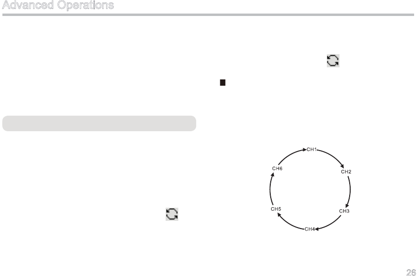
Channel Scan
T he S c a n f e a t u r e e na b le s a t wo - wa y r ad i o to
continuously scan each channel for activity. It can be
programmed by your dealer.
When entering Scan mode, the radio sounds an alert
tone (programmable), and then scan starts from the
current channel and goes in order of the channel
number. During scanning, the LCD displays with
green LED ashing. If any signal is received on a certain
channel with matching signaling, the radio will switch
to this channel for the conversation; meanwhile, green
LED solidly glows.
When exiting from Scan mode, the radio also sounds an
alert tone (programmable) and disappears.
No Priority Channel
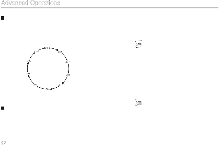
Suppose there is a scan list of 6 channels and all
channels are non-prioritized, the normal scan operation
may proceed in the following sequence, as shown in
Figure 1.
Advanced Operations
Figure 1 Normal Scan Sequence
27
Priority Channel Scan
Suppose there is a scan list of 5 channels and CH2 is
prioritized as Priority Channel 1, the scan operation may
proceed in the following sequence, as shown in Figure 2.
Figure 2 Priority Scan Sequence
Scan On/Off
There are three ways to access Scan mode:
1. When the radio is in Standby mode, press the
programmed Scan key on the channel assigned
with a scan list.
2. When Auto Scan is enabled for the channel
assigned with a scan list, the radio will start to scan
automatically when it switches to the channel.
3. Enter the main menu, select “Scan → On”, and
press to conrm.
There are seven ways to exit from Scan mode:
1. Press the programmed Scan key again during
scanning.
2. The radio will automatically exit from Scan mode
when switches to a channel with no scan list or with
Auto Scan off.
3. Enter the main menu, select “Scan → Off”, and
press to conrm.
4. Press the Call key to transmit.
5. Press the PTT to transmit (except PTT ID).
6. Start the Emergency function.
7. Turn the radio off.
Advanced Operations
28
Scan Stay
If a matching signal is detected on a Scan List member,
or the PTT or Monitor key is pressed, the radio will stay
on the channel. At this time, the LCD displays and
the corresponding channel number. When the scan
stays on a priority channel, “ ” (Priority Channel 1)
will appear on the LCD.
Talk Back
With this feature enabled, you can talk back on the
channel where scanning pauses.
Enabled: When the radio is staying on a scanned
channel, it transmits on the scanned channel;
when the radio is not staying on a scanned channel, it
transmits on a preset channel.
Disabled: During scanning, the radio transmits on the
preset channel.
Priority Scan
With this feature enabled, you can scan the most
frequently used channel so that information will not be
missed. These priority channels can be programmed by
your dealer via programming software. Please contact
your dealer for more information.
The radio supports only one priority channel. When
scan stays on a non-priority channel, the radio will keep
detecting activities on the priority channel. Once any
activity is detected, it will jump to the priority channel.
Advanced Operations
Note:
1. You can create one scan list for each channel and
32 channels at most can be included in the list.
2. During scanning, the radio will not respond to
operation of the following functions: Power Adjust,
Compandor, Scrambler, Whisper and Keypad
Mode.
3. To ensure fast scan speed, the frequency of
adjacent channel should not exceed 30MHz.
29
Emergency
When encountering any emergency or unforeseen
situations, you can signal for immediate help by
activating this feature. It can be programmed by your
dealer.
Emergency Start
Press the programmed Emergency On key, and the icon
appears to indicate the successful entry.
Emergency Exit
The radio will return to the previous operating channel
after it exits from Emergency mode. And the icon
disappears accordingly. Ways to exit from Emergency
mode include:
1. Press the programmed Emergency Off key.
2. The radio will automatically exit the Emergency
mode after the programmed number of Emergency
Alarm Cycle is used up.
Advanced Operations
3. Turn the radio off.
Emergency Mode
If the radio enters Emergency mode, it will switch to the
preset Emergency Revert Channel. The alarm process
includes four stages: Transmit ID, Transmit Alarm,
Transmit Background Audio, and Forcibly Receive. Your
dealer can program times and duration that the radio
cycles during each stage. Please ask your dealer to
program one of the following characteristics:
1. No alarm tone available ;
2. Alarm tone audible for the transmitting party only;
3. Alarm tone audible for the receiving party only ;
4. Alarm tone audible for both parties.
Time-out Timer (TOT)
The purpose of TOT is to prevent any single user
from using a channel for an extended period, and to
protect the radio against damage caused by prolonged

30
Advanced Operations
transmission. If the preset time expires, the radio will
automatically terminate transmission and keep beeping
until the PTT key is released.
Your dealer may program a pre-alert function, so as to
alert you to the TOT expiration in advance.
Time-out Time
If the programmed time-out time expires, the radio will
automatically terminate transmission and keep beeping
until the PTT key is released.
TOT Pre-Alert Time
The radio will generate pre-alert tone before the
programmed TOT pre-alert time expires, to make you
aware that transmission will be prohibited soon.
TOT Re-Key Time
After the PTT key is released, transmission will remain
inhibited until TOT Re-Key Time expires.
TOT Reset Time
Two transmissions with time interval shorter than the
programmed TOT Reset Time will be deemed as a
continuous transmission.
Battery Save
With this feature enabled, your radio can conserves
batt er y power t o exten d it s du ty ti me . It ca n be
programmed by your dealer.
In standby mode, if the radio is inactive (no key press/
transmission/reception) for 10 seconds (programmable),
it will automatically enter Battery Save mode. And it
would exit the Battery Save mode and get activated
once any key is pressed or any signal is received.
Note: This feature is null in Emergency mode.
31
Compandor
With this feature enabled, you can hear clear and crisp
voice even in noisy environment. Press the programmed
Compandor key to toggle this function on or off. You
can also ask your dealer to assign this feature to a xed
channel. When this feature is enabled, the alert tone
sounds once and appears; when it is disabled, the
alert tone sounds twice and the icon disappears.
Display Mode Switch
This feature allows you to change the display mode of
channel information: Number, Alias or Frequency. Ways
to switch the display mode are shown as below:
Press the programmed Display Mode Switch key;
Enter “Settings → CH Display” through the main
menu, select your desired display mode, and press
to conrm.
Advanced Operations
Home Channel
You can ask your dealer to assign the frequently used
channel as the Home channel. This feature allows you to
fast switch to the Home channel. Ways to switch include:
Manual Entry
Press the programmed Home Channel key to switch;
and appears on the LCD accordingly. Press this key
again to return to the previous channel.
Auto Entry
You can ask your dealer to assign this feature to a xed
channel. If the non-home channel is inactive, the radio
will switch to the Home channel upon expiration of
the programmed auto reset time, and will appear
accordingly.
Note:The radio supports only one Home
channel.
32
Keypad Mode
This feature enables you to choose one of the keypad
input modes: Disabled, Frequency, Channel and DTMF.
Ways to switch the modes include:
Press the programmed Keypad Mode key.
Enter “Keypad Mode” through the main menu,
select your desired keypad mode, and press to
conrm.
According to these four keypad modes, the radio
supports the following operations in Standby mode:
Disabled:
The numeric keypad is disabled. You can only press
/ to switch channels.
Channel:
You can input a Channel Number through the numeric
keypad, and press to go on the channel. If the
channel does not exist, an Error alert will sound. And
you may also press / to switch channels.
DTMF:
You can input a DTMF code through the numeric keypad
(To create A, B, C and D, respectively double-press 3, 6,
9 and #), and press PTT to transmit. You should set the
time and TX signaling (The TX signaling must be set to
DTMF) via the programming software at rst.
Frequency:
You can input a frequency through the numeric keypad
(press to input a decimal point), and press to
switch to the desired frequency. Simultaneously, LCD
displays the frequency compulsively. Press / to
switch the channel, and the LCD restores the previous
display mode. If any illegal frequency is detected, you
will be warned of the wrong input by an alert.
Advanced Operations
33
Please note that if the radio power is restored, the input
frequency remains valid. However, if the channel is
switched, this frequency will become invalid.
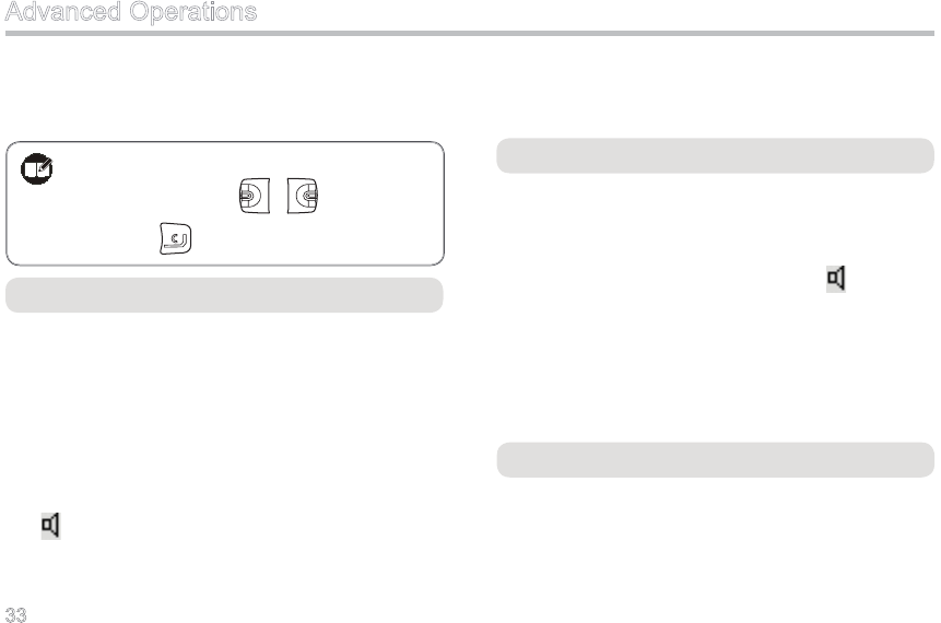
Monitor
In this mode, the receiving party can receive incoming
calls regardless of CTCSS/CDCSS condition. However,
if the frequency consistency between two radios is
not satised, the receiving party will fail to receive any
incoming calls.
In non-auto reset mode, press the programmed Monitor
key to enable this feature; the alert tone will sound once
and will appear accordingly. Press this key again to
disable this feature; at this time, the alert tone will sound
twice and the icon will disappear.
In auto reset mode, press Monitor to cancel a call.
Monitor Momentary
Refer to Monitor for purpose of Monitor Momentary.
In non-auto reset mode, press and hold down the
programmed Monitor Momentary key to enable this
feature; the alert tone will sound once and will appear
accordingly. Release this key to disable this feature; at
this time, the alert tone will sound twice and the icon will
disappear.
In auto reset mode, press Monitor Momentary to cancel
a call.
Scrambler
This technology can encrypt audio signals, and provide
sound security for privacy between communication
parties.
Advanced Operations
Note:You can move the cursor to a wrong
character using / key, and then
press key to delete it.
34
Press the programmed Scrambler key to toggle this
function on or off. You can also ask your dealer to assign
this feature to a fixed channel. When this feature is
enabled, the alert tone sounds once and appears;
when it is disabled, the alert tone sounds twice and the
icon disappears.
Squelch Off
In this mode, the speaker is unmuted in any condition so
as to receive any sound on the current channel. When
audio signal is received on the channel, audio will be
heard. Otherwise, background noise will be heard.
In non-auto reset mode, press the programmed Squelch
Off key to enable this feature; the alert tone will sound
once and will appear accordingly. Press this key
again to disable this feature; at this time, the alert tone
will sound twice and the icon will disappear.
In auto reset mode, press Squelch Off to cancel a call.
Squelch Off Momentary
Refer to Squelch Off for purpose of Squelch Off
Momentary. When audio signal is received on the
channel, audio will be heard. Otherwise, background
noise will be heard.
In non-auto reset mode, press the programmed Squelch
Off Momentary key to enable this feature; the alert
tone will sound once and will appear accordingly.
Release this key to disable this feature; at this time, the
alert tone will sound twice and the icon will disappear.
In auto reset mode, press Squelch Off Momentary to
cancel a call.
Voice-operated Transmit (VOX)
With a dedicated earpiece, the radio can automatically
begin to transmit when you speak, and terminate
transmitting when you stop talking. If VOX is enabled,
appears on the LCD, and you may follow steps
below in Conventional mode:
Advanced Operations
35
1. Set the PTT/VOX Switch on the earpiece to VOX;
2. Plug the earpiece into the accessory jack;
3. Press the programmed VOX key to activate VOX;
4. Speak into the earpiece microphone and your voice
will be transmitted.
Operation Instruction:
1. Press the programmed VOX key to activate or
deactivate VOX.
2. The VOX feature may get disabled automatically if
the radio is turned off or programmed.
3. Yo u c a n s e t t h e V O X s e n s i t i v i t y t h r o u g h
programming software or menu operation to inhibit
VOX.
Note:
1. If the PTT/VOX Switch on the earpiece is set to
PTT, you can only transmit by pressing the external
PTT, no matter whether VOX is activated.
2. When the PTT/VOX Switch is set to PTT, you are
not allowed to switch it from PTT to VOX directly;
otherwise, continuous transmission may occur.
If continuous transmission occurs unexpectedly,
you can restore the radio to normal operation by
pushing the switch from VOX to PTT, or turning the
radio off and back on.
3. You can select an appropriate VOX sensitivity
according to the operating environment. If VOX
is activated under heavy noise, continuously
transmission may occur.
Advanced Operations
36
Reverse Display
With this feature, the displayed text can be reversed by
180 degrees.
Press the programmed Reverse Display key to reverse
the displayed text; and the alert tone will sound once.
Press the key again to restore normal display; and the
alert tone will sound twice.
Advanced Operations
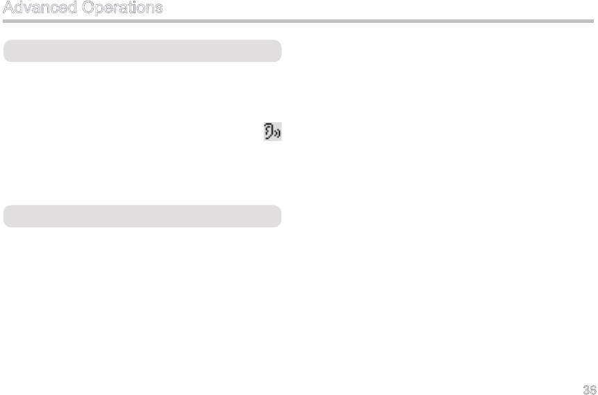
Whisper
With this feature, even if you speak at a low voice, your
voice can be heard clearly.
Press the programmed Whisper key to enable this
feature; then the alert tone sounds once and
appears. Press the key again to disable this feature;
at this time, the alert tone sounds twice and the icon
disappears.

37
Troubleshooting
The radio can not be The battery may have been improperly installed. Remove the battery and attach it again.
powered on.
The battery may have run out. Recharge or replace the battery.
The battery contacts may have been damaged Send the battery to your dealer or
(for example, deformed or broken). authorized service center for inspection
and repair.
During receiving signals, The battery strength may have been too low. Recharge or replace the battery.
the voice is weak, The volume may have been set to a low level. Increase the volume.
discontinuous or totally The antenna may have got loose or it may have Power off the radio, re-install the
inactive. been improperly installed. antenna and power on the radio again.
The Mic may have been blocked or damaged. Send the battery to your dealer or
authorized service center for inspection
and repair.
You can not communicate The frequency or CTCSS/CDCSS may Set your CTCSS/CDCSS the same as
with other members. have been inconsistent with that of other that of other members.
members.
Phenomena Analysis Solution

38
Phenomena Analysis Solution
You can not communicate You may have been too far away from the Move towards other members. And
with other members. group members. make sure that you are within the
communication range.
Irrelevant communications The radio may have not been set with Set your CTCSS/CDCSS signaling the
or noises are heard on the CTCSS/CDCSS. same as that of other members.
channel. (Go to the dealer for this programming.)
The noise is too loud. You may have been too far away from other Move towards other members, power
members. off your radio and then restore its
power.
You may have been at an unfavorable Move to an open and at area, and
position. For example, your communication restore the radio power.
may have been blocked by high buildings or
frustrated in the underground areas.
Troubleshooting
If the above solutions can not x your problems, or you may have some other troubles, please contact us or your local
dealer for more technical support.

39
Care and Cleaning
Please try the following care and cleaning tips to guarantee
optimal performance of your radio.
■ Radio Care
Do not hold the radio by its antenna or earpiece directly.
Keep the radio far away from substances that can corrode
the electronic circuit.
Attach the accessory jack cover when the radio is not in use.
■ Radio Cleaning
Clean up the dust and ne particles on the radio surface and
charging piece with a clean and dry lint-free cloth or a brush
regularly.
Use neutral cleanser and a non-woven cloth to clean the
keys, control knobs and front case after long-time use. Do
not use chemical preparations such as stain removers, alco-
hol, sprays or oil preparations, so as to avoid surface case
damage. Make sure the radio is completely dry before use.
40
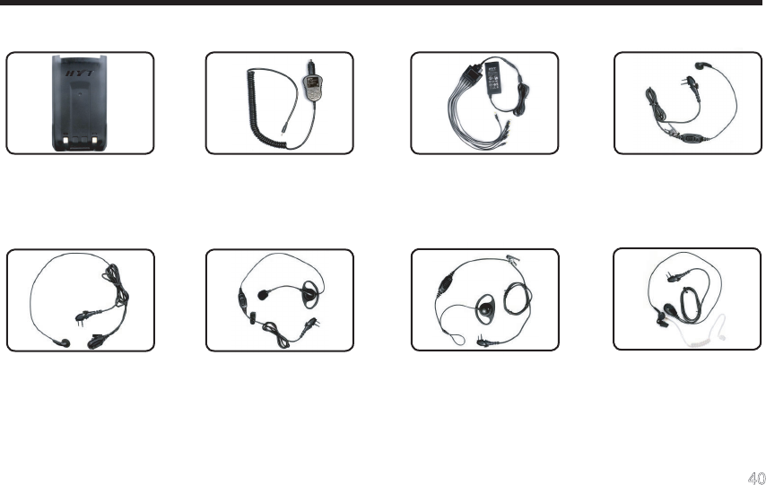
Optional Accessories
Li-Ion Battery (2000mAh)
BL2003
Vehicle Desktop Adapter
CHV09
Earbud with in-Line PTT &
VOX ESM11
Earbud with on-MIC PTT
& VOX ESM12
D-earset with Boom MIC &
VOX EHM16
Earpiece with on-MIC
PTT & VOX& Transpar-
ent Acoustic Tube EAM12
D-earset with in-Line
MIC & VOX EHM15
Six-unit Switching Power
PS7002 (The power cable
may vary in different coun-
tries and areas)
41
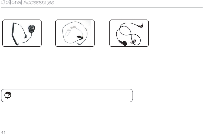
Remote Speaker Mi-
crophone SM08M3
Receive-Only Ear-
piece with Transparent
Acoustic Tube (for use
with remote speaker
microphone) ESS08
Receive-Only Earbud
(for use with remote
speaker microphone)
ESS07
Note:Pictures above are for reference only and may vary from actual
product. However, featuring functions shall be held.
Optional Accessories