HYT Science and Technology Co TC1600 FM Handheld Transceiver User Manual TC 1600 User s Manual
Shenzhen HYT Science &Technology; Co Ltd FM Handheld Transceiver TC 1600 User s Manual
Users Manual
THANK YOU!
We are grateful for your purchase of HYT product. We believe this easy–to-use
radio will provide you with dependable and reliable communications. This HYT
portable two-way radio is a precision device. Treat it with care, and you will enjoy
years of reliable operation.
MODELS COVERED IN THIS MANUAL
TC-1600 UHF Two-way Radio

TC-1600 Owner’s Manual
1
CONTENTS
User Safety, Training, and General Information
Compliance with RF Energy Exposure Standards
FCC Compliance
Precautions
Product Inspection
Battery Information
Accessory Installation
Getting Started
LCD Display
Features and Operations
Basic Operation
Turning On/Off the Radio
Operations under Radio Modes
Conventional Mode
Clock and Alarm Clock Setting Mode
Channel Setting Mode
Menu Mode
PC Programming Mode
Wired Clone Mode
Default Setting Mode
Appendix 1: Channel Frequency
Appendix 2: CTCSS Table
Appendix 3: CDCSS Table
Troubleshooting Guide
Care and Cleaning
Optional Accessories
Frequency Chart

TC-1600 Owner’s Manual
2
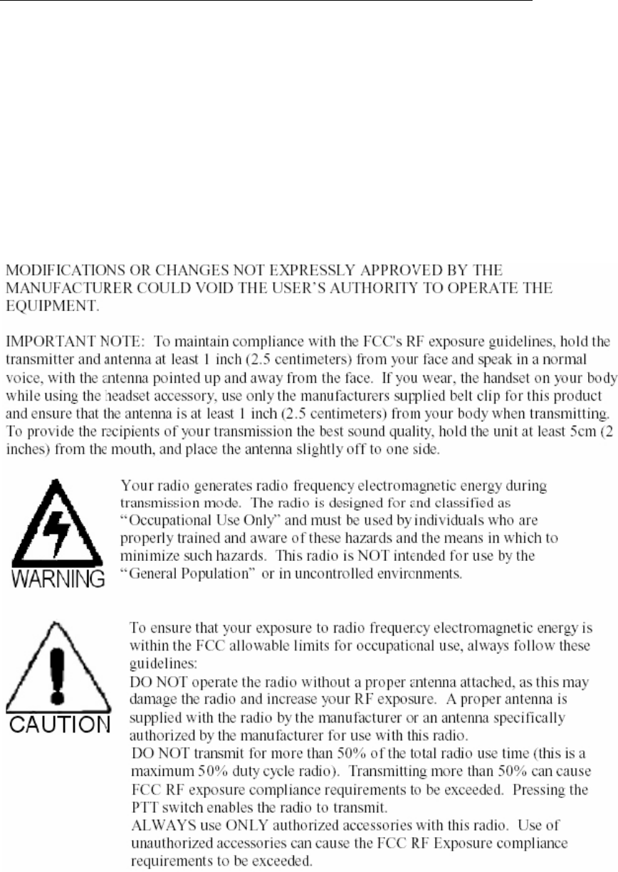
User Safety, Training, and General Information
READ THIS IMPORTANT INFORMATION ON SAFE AND EFFICIENT OPERATION
BEFORE USING YOUR HYT PORTABLE TWO-WAY RADIO.
Compliance with RF Energy Exposure Standards
Your HYT two-way radio is designed and tested to comply with a number of national and
international standards and guidelines (listed below) regarding human exposure to radio
frequency electromagnetic energy. This radio complies with the IEEE (FCC) and ICNIRP
exposure limits for occupational/controlled RF exposure environment at duty cycles of up
to 50% talk-50% listen and should be used for occupational use only. In terms of
measuring RF energy for compliance with the FCC exposure guidelines, your radio
radiates measurable RF energy only while it is transmitting (during talking), not when it is
receiving (listening) or in standby mode.
Note: The approved batteries supplied with this radio are rated for a 5-5-90 duty cycle
(5% talk-5% listen-90% standby), even though this radio complies with the FCC
occupational RF exposure limits at duty cycles of up to 50% talk.
Your HYT two-way radio complies with the following of RF energy
exposure standards and guidelines:
z United States Federal Communications Commission, Code of Federal Regulations;
47CFR part 2 sub-part J
z American National Standards Institute (ANSI)/Institute of Electrical and Electronic
Engineers (IEEE) C95. 1-1992
z Institute of Electrical and Electronic Engineers (IEEE) C95. 1-1999 Edition
z International Commission on Non-Ionizing Radiation Protection (ICNIRP) 1998
Operational Instructions and Training Guidelines
To ensure optimal performance and compliance with the occupational/controlled
environment RF energy exposure limits in the above standards and guidelines, users
should transmit no more than 50% of the time and always adhere to the following
procedures:
Transmit and Receive
To transmit (talk), push the Push-To-Talk (PTT) button; to receive, release the PTT button.
Hand-held radio operation
Hold the radio in a vertical position with the microphone one to two inches (2.5 to 5 cm)
away from the lips.
Body-worn operation
z Always place the radio in an HYT approved clip, holder, holster, case, or body
harness for this product. Use of non-HYT-approved accessories may exceed FCC
RF exposure guidelines.
TC-1600 Owner’s Manual
3
Antennas & Batteries
z Use only HYT approved, supplied antenna or HYT approved replacement antenna.
Unauthorized antennas, modifications, or attachments could damage the radio and
may violate FCC regulations.
z Use only HYT approved, supplied batteries or HYT approved replacement batteries.
Use of non- HYT -approved batteries may exceed FCC RF exposure guidelines.
Approved Accessories
For a list of HYT approved accessories, see the accessories page of this user manual or
visit the following website which lists approved accessories: http://www.HYT.com.cn
FCC Information

TC-1600 Owner’s Manual
4
User Safety Information
READ THIS IMPORTANT INFORMATION ON SAFE AND EFFICIENT OPERATION
BEFORE USING YOUR HYT PORTABLE TWO-WAY RADIO.
◇ Only qualified technicians are allowed to maintain this product.
◇ To avoid electromagnetic interference and/or compatibility conflicts, turn off your radio
in any place where posted notices instruct you to do so. Hospitals or health care
facilities may be using equipment that is sensitive to external RF energy. When on
aircraft, turn off your radio when airline crew instruct you to do so.
◇ When in vehicles with an airbag, do not place a portable radio in the area over an
airbag or in the airbag deployment area.
◇ Turn off your radio prior to entering any area with a potentially explosive atmosphere.
Do not remove, install, or charge batteries in such areas.
◇ To avoid possible interference with blasting operations, turn off your radio when you
are near electrical blasting caps.
◇ Do not use any portable radio that has a damaged antenna. If a damaged antenna
comes into contact with your skin, a minor burn may result.
◇ Do not expose the radio in direct sunlight for a long time or place it close to a heating
source.
◇ When transmitting with a portable radio, hold the radio in a vertical position with its
microphone about 5 centimeters away from your mouth.
◇ If you wear a portable two-way radio on your body, ensure that the antenna is at least
2.5 centimeters from your body when transmitting.
◇ The communication range will be impacted in rainy or cloudy days or when you are in
forest.
TC-1600 Owner’s Manual
5
Product Inspection
Thank you for your use of HYT portable two-way radio TC-1600. Before use, you are
recommended to inspect the product as follows.
First check the shipping carton for any signs of damage. If any damage has occurred,
please contact your dealer immediately. Confirm the supplied product against the packing
slip to assure accuracy.
Available Accessories
Item Qty. (pcs)
Battery 1
Desktop Charger 1
Switch power 1
Belt Clip 1
Strap 1
Owner’s Manual 1

TC-1600 Owner’s Manual
6
Battery Information
Initial Use of the Battery
The battery is not fully charged at the factory. Please charge the new battery before initial
use. In general, the battery should be charged for 12 hours before initial use, which is
suitable for Ni-Cd, Ni-MH or Li-ion battery charged with slow or rapid charger. It is
recommended to take this step during the first three times of use. When the battery power
is low, it needs to be charged.
Applicable Battery Packs
Charge only the HYT approved battery packs. Other batteries may burst and cause
personal injury.
Safety attention
1. Conductive metals including jewelry, key, etc, may result in short circuit, discharge,
generation of a large quantity of heat, or leakage when coming into contact with battery
contacts or electrodes. To avoid damage to articles or human injury, treat any battery with
care.
2. Do not short out the battery terminals or dispose of the battery in fire. Never attempt to
disassemble the battery. If discarded, the battery should be thrown into dedicated battery
recycle box.
Normal operation
★ Please charge the battery indoor to ensure the optimal charging effect.
★ In general, the battery can be removed if the charger indicator turns from red to green.
★ Turn off the radio when charging the battery inside the radio.
★ Do not charge the battery if its power hasn’t been used up (if the power used up, the
battery meter flashes), otherwise, the battery life will be shortened.
★ Do not return fully charged batteries to the charger for an “extra boost”. This action will
significantly reduce cycle life.
To prolong battery life
★ Battery performance will be greatly decreased under -20℃ temperature. Please use
back-up battery in cold weather. The cold battery unable to work in this situation may work
under room temperature, so keep it for later use.
★ The dust on the battery contact may affect the life cycle of the battery. Please use
clean dry cloth to wipe it before the insertion of the battery into the radio.
Battery storage notice
1. Due to the self-discharge, the battery which will not be used for a long time should be
stored after full charge to avoid the damage to the battery because of over-discharge.
TC-1600 Owner’s Manual
7
2. Take out the battery stored for about 6 months to charge it, to avoid the influence of
electrolyte over-discharge on battery capacity.
3. Notice the ambient humidity and temperature for the battery storage. Please store it in
cool dry area with room temperature, to decrease self-discharge.
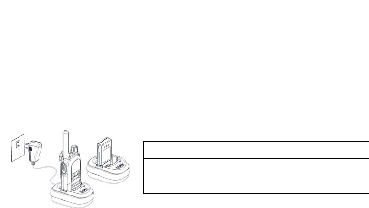
Battery charging
You are recommended to use HYT-approved, supplied charger; Charger LED will indicate
the charging status.
1. Plug the power cable into the adapter.
2. Plug the DC socket of adapter into the DC jack on the rear of the charger.
3. Insert the battery or the radio with battery into the charger cup.
4. Plug the AC socket of adapter into an AC outlet.
5. Make sure that the battery connectors are in contact with the charging terminals; the
charger LED glows red and charging begins.
6. The charger LED glows green when the battery is fully charged in about 2 hours,
please remove the battery or the radio with battery from the charger.
NOTE:
1. When a fully charged battery is inserted into the charger:
¾ LED glows red, indicating charge is in absorption stage, which helps to charge
the battery to its full capacity. In this stage, the charging current is very small
and the stage will last about less than 5 minutes and then LED turns green.
¾ LED glows green.
¾ LED goes from red to orange and finally to green. And the LED glows orange
for about 10 seconds.
Any status is possible and normal and will not affect normal operation.
LED Indication
Red Charging
Green Fully charged or no battery inserted
TC-1600 Owner’s Manual
8
Accessory Installation
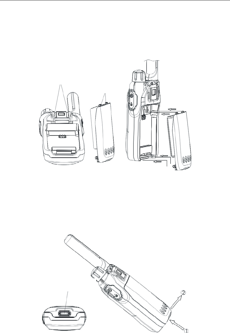
Battery
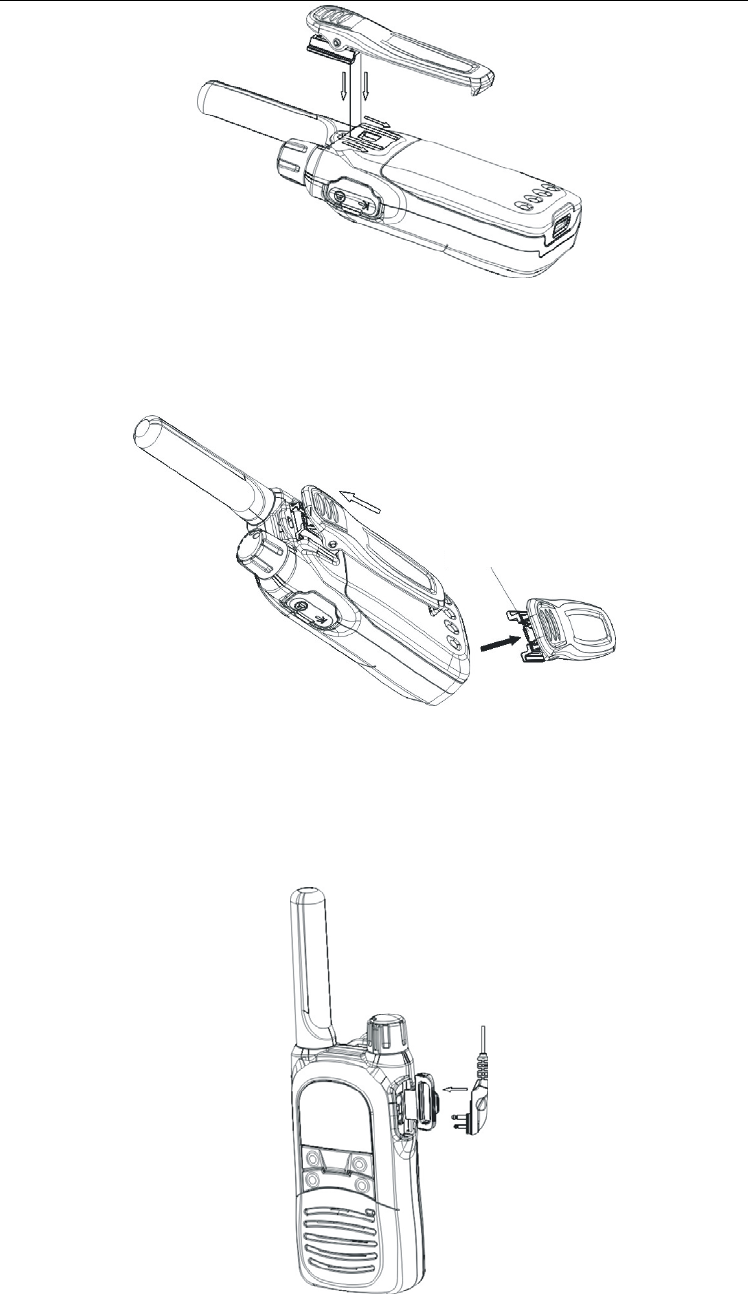
Attaching the battery:
Insert the two tabs on bottom of the battery into the slots at the bottom of the radio. Push
the top of the battery towards the radio until a click is heard. (See figure 1)
卡槽
卡骨
(Fig1)
Removing the battery:
Turn off the radio. Push the battery latch on the bottom of the radio upwards for 1-2mm to
remove the upper side of the battery away from the radio and then remove the battery.
(See figure 2)
电池推钮
(Fig2)
Belt Clip
Attaching Belt Clip:
Push the grooves of the belt clip along those at the top of the radio chassis and pull the
clip along the indicated direction until a click is heard. (See fig.3)
Slot
Tab
Battery Latch
TC-1600 Owner’s Manual
9
(Fig 3)
Press the tab between the battery cover and the belt clip along the indicated direction.
Slide the belt clip upwards along the radio chassis to detach the clip from the radio. (See
fig.4)
(Fig4)
External Earphone/Microphone (Optional)
Open the earphone/microphone Jack cover (unnecessary to remove) and plug your
earphone/microphone into the jack (See fig 5).
(Fig 5)
Metal holder of belt clip
TC-1600 Owner’s Manual
10
Getting Started
1
2
3
4
5
6
7
10
11
12
13
14
15
16
17
MON
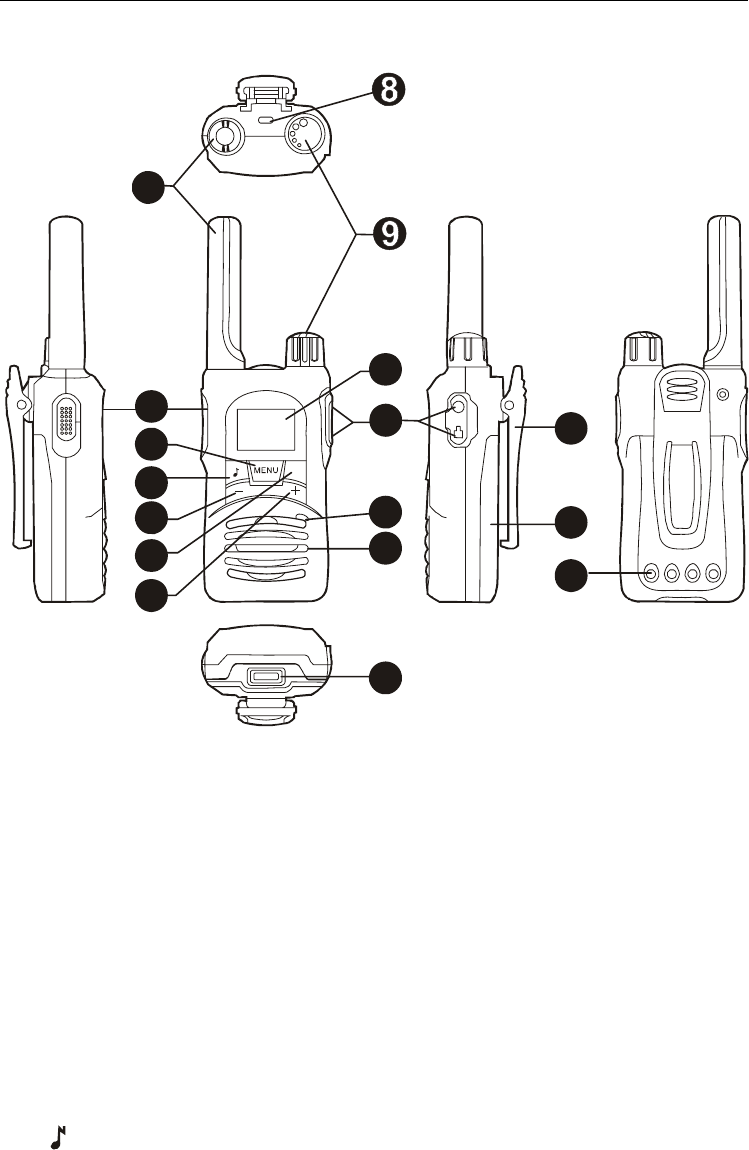
1. Antenna
2. PTT key
In normal work mode, press the key to transmit (no button beep) either in standby or
menu mode. When the key is pressed in menu mode, the channel information will be
displayed on the screen at the same time. And the display returns to its original
display when the PTT key is released.
3. MENU key
Press the key in standby mode to display current channel information. Press and hold
the key to enter setting mode. When setting the parameters, press the key to confirm
your setting and move to another setting item,.
4. “ “ key
Press the key in standby mode to transmit CALL signal (Special frequency or
frequency combination code). Press and hold the key to lock/unlock the keypad. In
menu mode or setting mode, press the key to confirm the setting and return to the
first item. Press the key when setting the first item to exit.
5. DOWN (-) key
Down key or minus key. The key is also used as channel or interference-eliminate

TC-1600 Owner’s Manual
11
code (CTCSS or CDCSS) selector. Press the key in menu mode to go to your
required setting item. When channel information is displayed on the screen in
standby mode, press the key to go to next channel. Press and hold the key to scroll
the channels at the speed of 250ms per channel.
6. Moni key
Press the key in standby mode to enter channel-scan mode. Press and hold the key
to monitor the activities on current channel.
7. Up (+) key
Up or plus key. The key is also used as channel or interference-eliminate code
(CTCSS or CDCSS) selector. Press the key in menu mode to go to your required
setting item. When channel information is displayed on the screen in standby mode,
press the key to go to next channel. Press and hold the key to scroll the channels at
the speed of 250ms per channel.
8. Strap hole
9. Power/Volume Knob
Turn the knob clockwise until a “click” is heard to turn the radio on; fully counter
clockwise to turn it off. When the radio is on, turn clockwise to adjust volume up and
counter clockwise to volume down.
10. Display
Used to display channel number, frequency code and interference-elimination code
and other parameters.
Please refer to Display section for details.
11. Earphone Jack and programming port
12. Microphone Jack (MIC)
Used to input voice.
13. Speaker Jack (SPK)
Used to output voice.
14. Battery Latch
Press and push the latch to release the battery.
15. Belt Clip
Used to wear your radio on the belt for easy carry.
16. Battery
17. Charging Connectors
Contact the connectors with the electrode piece oUsed to wear your radio on the belt
for easy carry.
TC-1600 Owner’s Manual
12
LCD Display
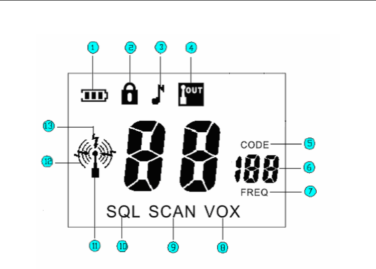
1. Battery Meter, used to indicate the battery power.
2. Appears when keypad is lock.
3. Appears when setting the call tone.
4. Communication Range Alarm, flashes when your companion is out of range; appears
when setting communication range alarm or communication range alarm is enable.
5. Interference Delete Code Icon: CTCSS and CDCSS are called interference delete
code. There are 38 CTCSS groups of CTCSS code numbered from 1-38 and 83 groups
CDCSS code numbered from 39-121.Indicate that the number on the LCD displays
interference eliminator code.
6. Two large “8” , a small “1” and two small “8” display the current channel number,
frequency number, interference eliminator code, status of current setting.
7. Frequency Number Icon: Indicate that the number on the LCD displays frequency
number or frequency number. The number under it indicates current frequency number.
8. VOX Icon: Appears when setting VOX or VOX feature is enabled.
9. Scan Icon: Appears when setting scan add/delete or when scanning channels.
10. Appears when setting squelch level.
11. Antenna Icon: Appears when the radio is standby, transmission and receive,
indicating that both receive and transmission are available.
12. Transmission Icon: Appears when transmitting
13. Receive Icon: Appears when receiving signal from current channel.

TC-1600 Owner’s Manual
13
Features and Operation
Basic Operation
Turn On/Off the radio
1. Turn on the radio, the radio emits a power-on tone and LCD fully displays
simultaneously. The radio is on about 2 seconds. Due to different key pressing, the radio
enters different modes:
A No key pressing and the radio enters conventional mode.
B Press MON key and PTT key together and hold for 2 seconds, the radio enters
channel setting mode.
C Press CALL key and NON key together and hold for 2 seconds, the radio enters
wired clone mode.
D Press “+” key and “-” key together and hold for 2 seconds, the radio enters default
setting mode.
If the keys are hold less then 2 seconds and released ahead of time, the operation will be
invalid and the radio enters conventional mode.
2. Fully rotate the power knob counter clockwise to power the radio off.
Conventional Mode
In conventional mode, LCD displays is shown as figure 1. Operations available are listed
as following:
Fig 1 LCD displays channel number
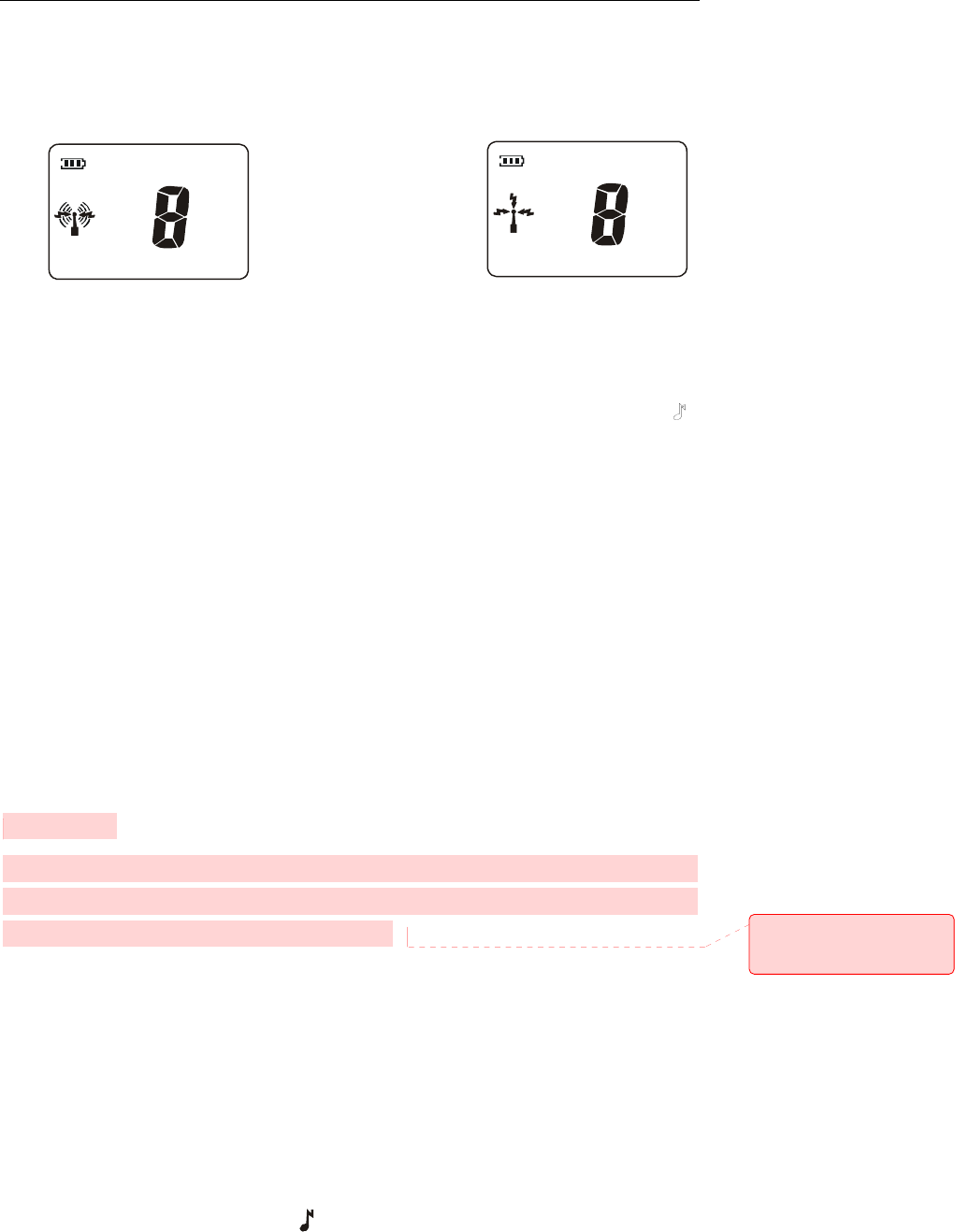
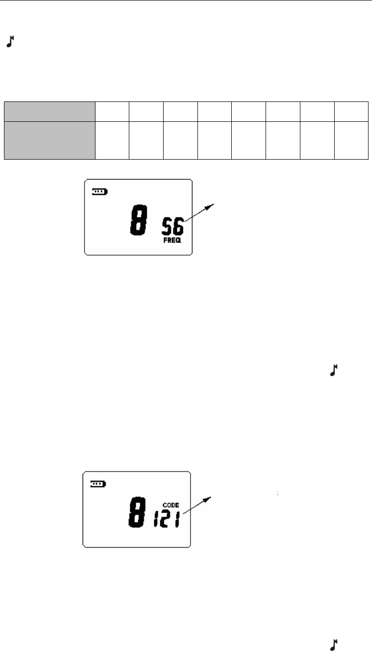
Receive and Transmission
Press the PTT key and talk into the microphone. “ ” appears on the LCD. See figure 2.
Release the PTT key or when transmission exceeds preset time, the radio return to
receive mode and “ ” disappears.
The receiving icon “ ” appears when the selected channel receives a signal (See
figure2(b), the speaker is opened and you can hear the voice. If interference eliminator
code is set on the channel, you will only hear the voice of the user with the same
interference eliminator code as you.
You can talk without holding the radio by using PTT on external earphone.
TC-1600 Owner’s Manual
14
Insert plug of earphone (with external PTT) into the accessory jack of the radio. Put on the
earphone and press PTT. Speak into the microphone to talk.
Fig 2 (a) Tx Interface Fig 2 (b) Rx Interface
Call Tone
The call tone feature is valid only when you have set a call tone in the menu mode. You
can send a call tone to your partner before begin talking with him/her. Briefly press “ ”
key to transmit a call. The call tone will sound when you receive a call.
This feature can be enabled/disabled by the dealer.
VOX Feature
This feature is valid only when the radio is connected with external audio accessory.
Insert plug of VOX accessory into the accessory jack of the radio, set the VOX Sensitivity
Level in the menu mode, and then speak into the microphone to talk. When transmitting
using VOX feature, you will hear yourself talking through the accessory speaker. VOX
feature allows you to talk hands-free.
Press PTT key on the radio to disable VOX feature. This feature is enabled when you turn
on the power next time.
This feature can be enabled/disabled by the dealer.
TOT Function
This feature defines the time period of transmission on certain channel, which avoids
possible damage to the radio caused by long-time transmission. The time period can be
set as one minute, 5 minutes or off by your dealer.
Channel Select
In conventional mode, pressing “+” / “-” key can select your wanted channel. The
maximum number you can select is decided by the number of available channels and the
minimum number is 1. Holding down “+” / “-” key can increase/decrease the channel
number continuously.
Keypad Lock
In conventional mode, holding down “ ” key can lock/unlock keypad. When keypad lock
批注 [w1]: 07.27 根据中文
第三次确认修改,增加内容
TC-1600 Owner’s Manual
15
is on, “ ” icon appears on the display and “+” / “-” and MON key are invalid. Holding
down MENU key and briefly pressing “ ” key are both invalid. The user can
transmit/receive through PTT key, briefly press MENU key to display channel information,
or hold down “ ” key to unlock the keypad.
This feature can be enabled/disabled by the dealer.
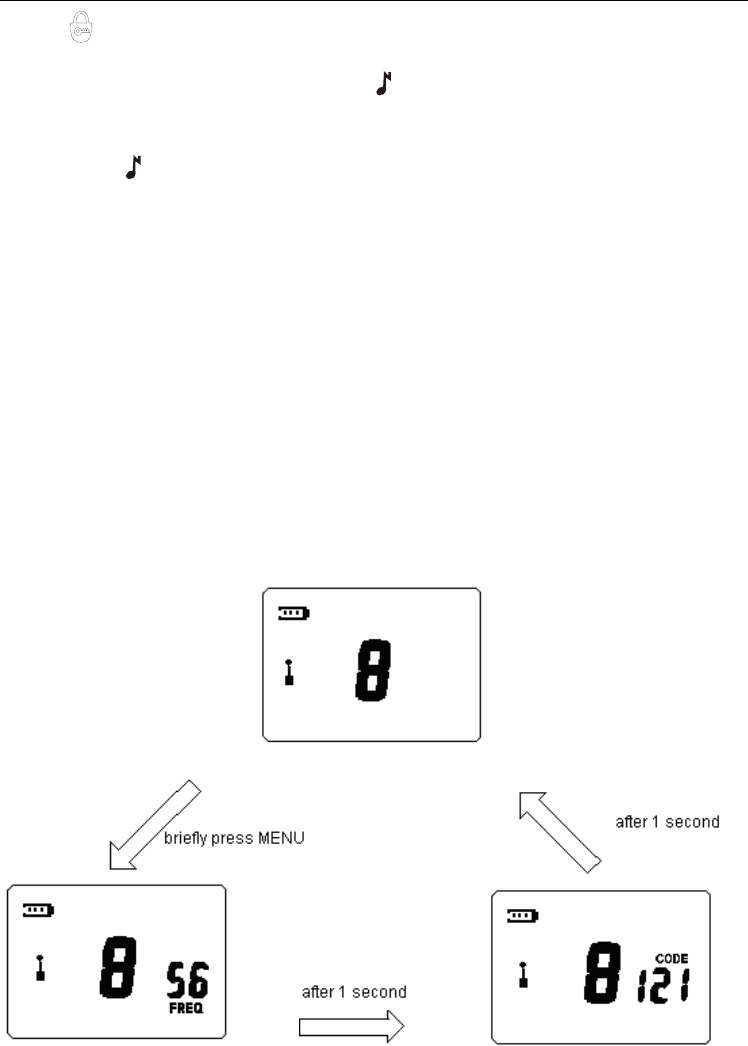
Channel Information Display
In channel number display mode, briefly press MENU key, LCD will display channel
number, frequency number and interference eliminator code of current channel.
For example, if LCD displays channel number in standby mode (See figure 3), and then:
Briefly press MENU key, LCD will display frequency number of current channel at bottom
right corner. “FREQ” icon glows at the same time. LCD switches to interference eliminator
code display automatically after 1 second and “CODE” icon glows at the same time. LCD
returns to display clock after another 1 second.
(Channel number display)
(Channel Number and Frequency Number display)
(Channel Number and Interference Eliminator Code display)
Fig 3 Channel Information Display
If the frequency indicated by the frequency number is changed through PC programming
software, LCD will display channel number and frequency number with an “n” in front of
the channel number indicating non-standard frequency number. (See figure 4)
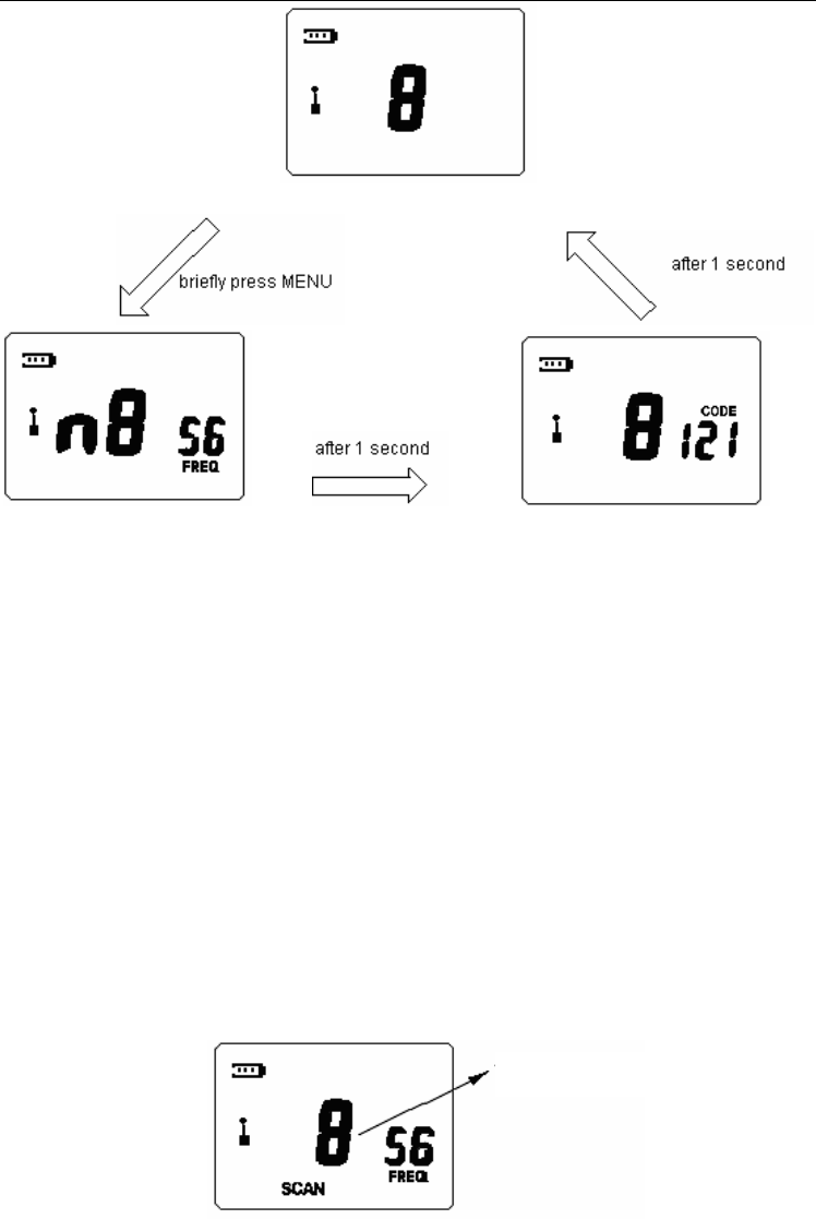
TC-1600 Owner’s Manual
16
(Channel Number display)
(Channel Number and non-stand Frequency Number display)
(Channel Number and Interference Eliminator Code display)
Fig 4 Channel Information Display
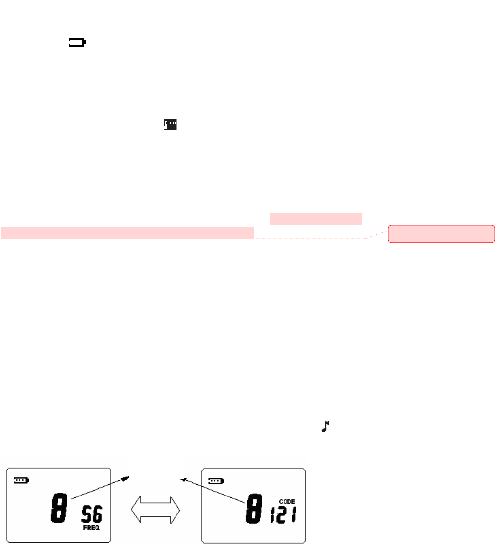
Channel Scan
Briefly press MON key in conventional mode to begin channel scanning. (See figure 5)
LCD displays “SCAN” icon, channel number and frequency number of the channel. The
radio will stay on the active channel when detecting a valid signal and then continue to
scan upwards. You can press “+” / “-” to scroll through the active channel and resume
scanning upwards.
Press PTT during scanning to transmit on the selected channel before scanning and LCD
displays channel information; release PTT to receive on the same channel and then return
to scan mode.
Briefly press MON key to stop scanning.
Fig 5 Channel Scan Status
Monitor
Press and hold MON key in conventional mode to begin monitoring.
This feature is used to receive weak signals, but will be interfered in by other noises
and/or unwanted signals.
Press MON key again to stop monitoring.
Channel number changes upwards
TC-1600 Owner’s Manual
17
Low Battery Detect and Battery Power Indication
The radio detects battery voltage periodically and indicates the battery power. The battery
power indicator “ ”on the top left corner of LCD will flash when the battery power is low.
You should recharge the battery or replace it with a fresh one.
Communication Range Alarm
The feature is valid only when you have enabled communication range alarm feature in
the menu mode.
The communication range alarm icon “ ” flashes and the radio beeps when you are
almost out of range during receiving. The beeps and flashing icon continue until you are
within the range again or turn the communication range alarm off.
This feature can be enabled/disabled by the dealer.
Battery Save
In conventional mode, when no activity is on channel and no key is pressed for 10
seconds, the battery save feature will be turned on automatically. In this mode, the radio
works normally for 200ms then turns to sleep mode for 600ms.
This feature can be enabled/disabled by the dealer.
Channel Setting Mode
Turn the power on while holding down MON and PTT key simultaneously. The radio
enters channel setting mode after 2 seconds. The current setting of channel setting will
flash when entering this mode. You can make settings as following:
Select Channel Number
During setting, the channel number flashes (See figure 6-1). LCD displays frequency
number and interference eliminator code of the current channel alternately. Press “+” / “-”
key to select channel number. The maximum number you can select is decided by the
number of available channels and the minimum number is 1.
Press MENU key to confirm the setting and switch to the next setting. Press “ ” key to
save the setting and to exit channel setting mode.
(a) Channel Number & Frequency Number display (b) Channel Number. & Interference Eliminator Code display
Fig.6 Channel Number Select
Set Frequency Number
When setting frequency number of the channel, “FREQ” icon appears on LCD and the
Blink
批注 [w2]: Translated
TC-1600 Owner’s Manual
18
frequency number flashes (See figure7). Press “+” / “-” key to select frequency number
from 1 to 56. Press MENU key to confirm the setting and switch to the next setting. Press
“” key to save the setting and return to the first setting or to exit channel setting mode.
This feature can be enabled/disabled by the dealer.
The factory default setting for frequency number of each channel is shown as following:
Channel Number 1 2 3 4 5 6 7 8
Frequency Number
7
15
16
31
34
45
48
52
Fig 7 Set Frequency Number
Set Interference Eliminator Code
When setting interference eliminator code of the channel, “CODE” icon appears on LCD
and the interference eliminator code flashes (See figure8). Press “+” / “-” key to select
interference eliminator code from 0 to 121. If “0” is selected, interference eliminator code
is not set in a channel.
Press MENU key to confirm the setting and switch to the next setting. Press “ ” key to
save the setting and return to the first setting or exit the channel setting mode.
This feature can be enabled/disabled by the dealer.
In factory default setting, interference eliminator code is not set in all channels.
Fig 8 Set Interference Eliminator Code
Set the number of available channels
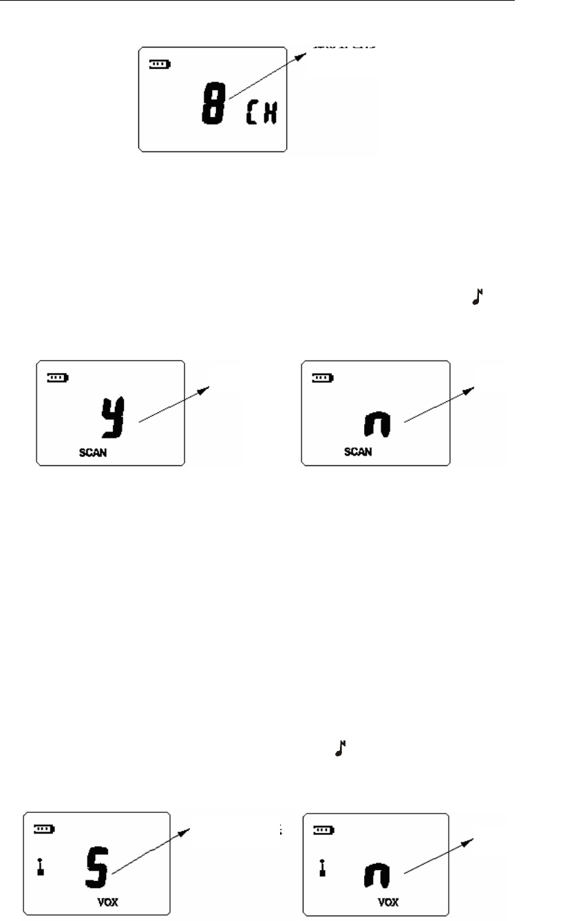
When setting the number of available channels, “CH ”icon appears on LCD and the
channel number flashes (See figure9). Press “+” / “-” key to select number of available
channels from 1 to 8.
Press MENU key to confirm the setting and switch to the next setting. Press “ ” key to
save the setting and return to the first setting or exit the channel setting mode.
Blink
Blink
TC-1600 Owner’s Manual
19
In factory default setting, the number of available channels is 8
Fig 9 Set the Number of Available Channels
Set Channel Scan Add/Delete
When setting channel scan add/delete, “SCAN” icon appears on the bottom of LCD and
the character “y” or “n” flashes (See figure10 (a) and 10 (b). “y” indicates channel scan
add while “n” indicates channel scan delete. Press “+” / “-” key to select between “y” and
“n”. Press MENU key to confirm the setting and switch to the next setting. Press “ ” key
to save the setting and return to the first setting or exit the channel setting mode.
In factory default setting, all the channels are added to scan list.
Fig 10 (a) Set Channel Scan Add Fig 10 (b) Set Channel Scan Delete
Menu Mode
The current setting of menu mode will flash when entering this mode. You can make
settings as following:
Set VOX Feature
When setting VOX feature, “VOX” icon appears on LCD and the VOX sensitivity level or
character “n” flashes (See figure11 (a)).
There are five sensitivity levels (level 1 to level 5). The higher the sensitivity level is, the
lower audio needed to trigger a transmission. The VOX feature is disabled when “n” is
selected.
Press “+” / “-” key to select sensitivity level or disable VOX feature. Press MENU key to
confirm the setting and switch to the next setting. Press “ ” key to save the setting and
return to the first setting or exit the menu mode.
In factory default setting, the VOX feature is disabled.
Blink Blink
Blink
Blink Blink
TC-1600 Owner’s Manual
20
a. Select VOX Sensitivity Level b. Disable VOX Feature
Fig 11 Set VOX Feature
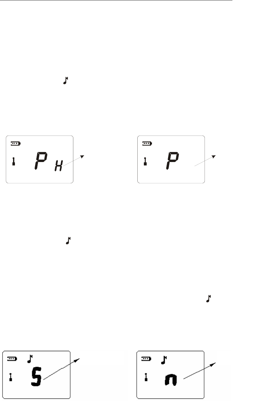
Select Power Level
When setting high-low level, character “P” appears on the left of LCD and Character “L” or
“H" blinks at the same time. “L” indicates low power while “H” indicates high power. Press
“+” / “-“to select between “L” and “H”. Press “MENU” key to confirm the setting and switch
to next one. Or press “ to confirm the setting and return to the first setting or to exit
menu mode (Press “CALL” to confirm and exit menu mode when setting the first item).
The feature can be enabled/disabled by your dealer.
In factory default setting, high level is on and the power level set as low power.
L
(a) High Power (b) Low Power
Fig 12 Select Power Level
Set Call Tone
When setting call tone, “ ” icon appears on LCD and the call tone number or character
“n” flashes (See figure13 (a)).
There are five distinct call tones (1-5). The call tone feature is disabled when “n” is
selected.
Press “+” / “-” key to choose from call tones 1-5 or disable call tone. The radio plays a
sample of each call tone as you select them.
Press MENU key to confirm the setting and switch to the next setting. Press “ ” key to
save the setting and return to the first setting or exit the menu mode.
In factory default setting, the call tone 1 is selected.
(a) select Call Tone (b) Disable Call Tone
Fig13 Set Call Tone
Blink Blink
Blink Blink
TC-1600 Owner’s Manual
21
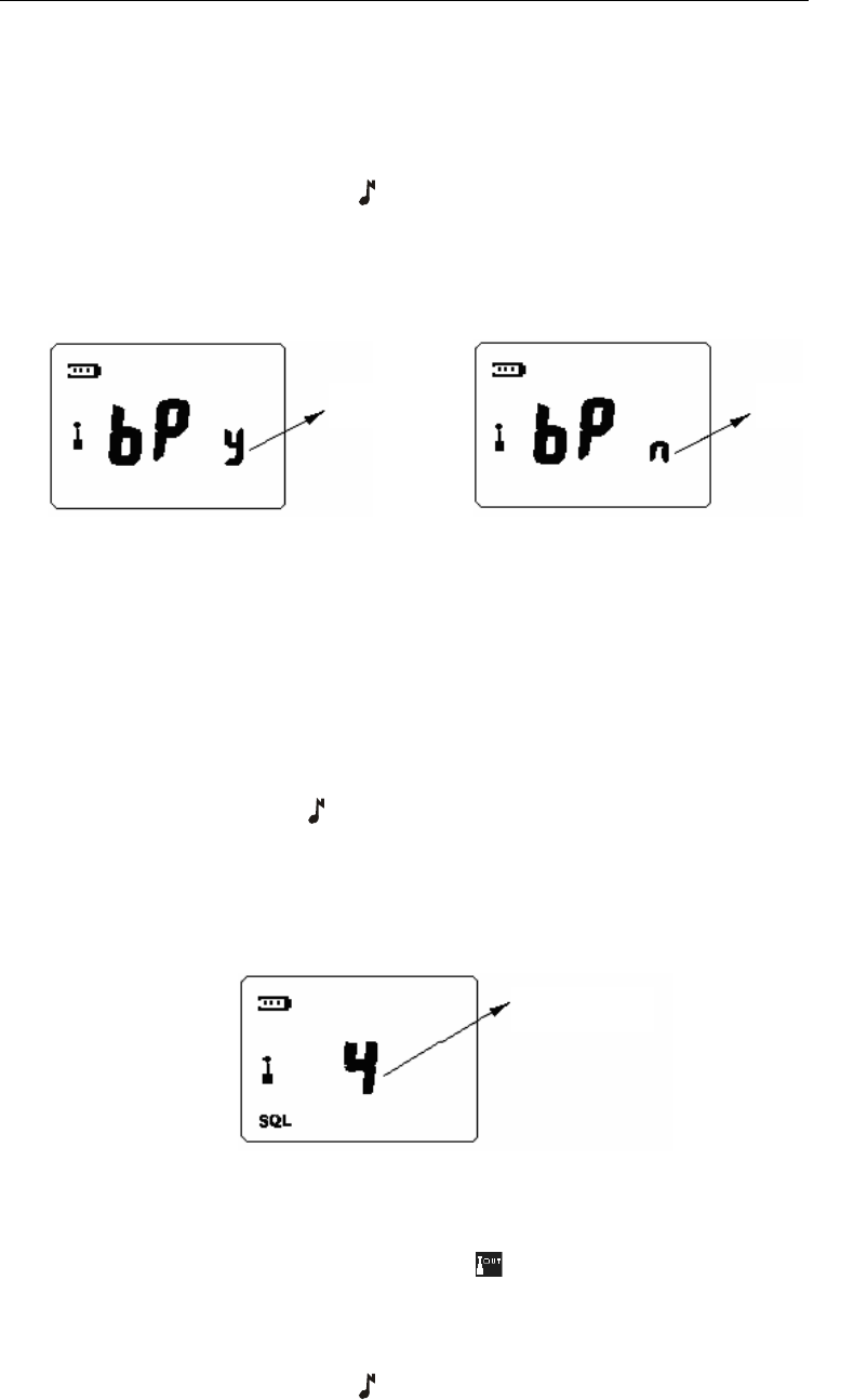
Set Button Beep
When setting button beep, “bP” icon appears on LCD and the character “y” or “n” flashes
(See figure20-1). “y” indicates enabling button beep and “n” indicates disabling.
Press “+” / “-” key to select between “y” and “n”. Press MENU key to confirm the setting
and switch to the next setting. Press “ ” key to save the setting and return to the first
setting or exit menu mode.
In factory default setting, the button beep is enabled.
a. Enable Button Beep b. Disable Button Beep
Fig 14 Set Button Beep
Set Squelch Level
When setting squelch level, “SQL” icon appears on bottom left corner of the LCD and the
squelch level flashes (See figure15).
There are four squelch levels (1-4). Higher squelch level makes it harder for the radio to
receive weak signals and avoid interference of noises and/or unwanted signals.
Press “+” / “-” key to select squelch level. Press MENU key to confirm the setting and
switch to the next setting. Press “ ” key to save the setting and return to the first setting
or exit the menu mode.
In factory default setting, squelch level is set as 2.
Fig15 Set Squelch Level
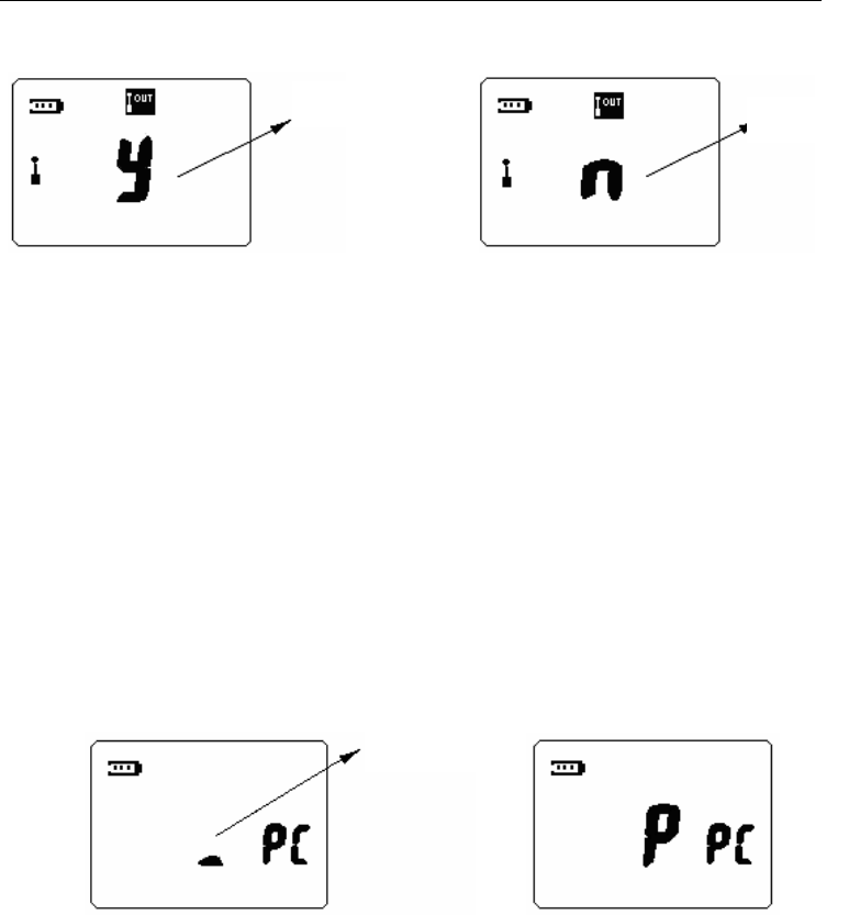
Set Communication Range Alarm
When setting communication range alarm feature, “ ” icon appears on the left of LCD
and the character “y” or “n” flashes (See figure16). “y” indicates enabling communication
range alarm and “n” indicates disabling.
Press “+” / “-” key to select between “y” and “n”. Press MENU key to confirm the setting
and switch to the next setting. Press “ ” key to save the setting and return to the first
setting or exit menu mode.
Blink Blink
Blink
TC-1600 Owner’s Manual
22
In factory default setting, the communication range alarm is disabled.
a. Enable Communication Range Alarm b. Disable Communication Range Alarm
Figure16: Set Communication Range Alarm
PC Programming Mode
In standby mode, connect the radio and a PC with programming cable and then
programme the radio through programming software, the radio enters PC programming
mode. LCD display is shown as figure17. During programming, the black cursor in the
center of LCD will scroll. When programming is complete, the character “P” will be
displayed on the center of LCD. In the PC programming mode, the radio communicate
with PC through UART port, all the commands are carried out via PC. After programming,
the radio should be turned off and back on again to use.
a. Programming b. Programming Over
Fig17 PC Programming Mode
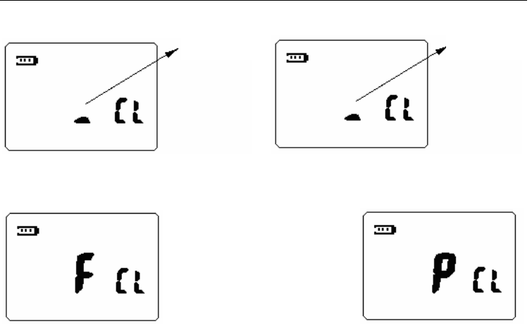
Wired Clone Mode
Connect the radio with cloning cable and then turn the power on while holding down CALL
and MON key simultaneously. After 2 seconds, the radio enters wired clone mode (source
side).
When the radio enters wired clone mode, LCD display is shown as figure18. The black
cursor in the center of LCD flashes. When the target radio is ready, press MON key to
begin cloning. The black cursor in the center of LCD will scroll. During cloning, if an error
occurs or the target radio has no response, the cloning stops and LCD displays error
prompt. “F” (FAIL) indicates that wired clone is failed. If data is cloned successfully, “P”
(PASS) appears.
Blink Blink
Scroll
TC-1600 Owner’s Manual
23
a. Wired Clone Ready b. Cloning
c. Clone Failure d. Clone Successfully
Fig18 Wired Clone
Default Setting Mode
This feature is used to enter conventional mode and restore all the radio settings to
factory default setting.
This feature can be enabled/disabled by the dealer.
Scroll Flash

TC-1600 Owner’s Manual
24
Annex 1. Frequency Chart (460MHz—470MHz)
Frequency No. Frequency (MHz)
Frequency No.
Frequency (MHz)
1 464.5000 29 462.9125
2 464.5500 30 464.4875
3 467.7625 31 464.5125
4 467.8125 32 464.5375
5 467.8500 33 464.5625
6 467.8750 34 466.0375
7 467.9000 35 466.0625
8 467.9250 36 466.0875
9 461.0375 37 466.1125
10 461.0625 38 466.1375
11 461.0875 39 466.1625
12 461.1125 40 466.1875
13 461.1375 41 466.2125
14 461.1625 42 466.2375
15 461.1875 43 466.2625
16 461.2125 44 466.2875
17 461.2375 45 466.3125
18 461.2625 46 466.3375
19 461.2875 47 466.3625
20 461.3125 48 467.7875
21 461.3375 49 467.8375
22 461.3625 50 467.8625
23 462.7625 51 467.8875
24 462.7875 52 467.9125
25 462.8125 53 469.4875
26 462.8375 54 469.5125
27 462.8625 55 469.5375
28 462.8875 56 469.5625

TC-1600 Owner’s Manual
25
Annex 2 CTCSS Table (38)
No. Frequency (Hz) No. Frequency (Hz)
1 67.0 20 131.8
2 71.9 21 136.5
3 74.4 22 141.3
4 77.0 23 146.2
5 79.7 24 151.4
6 82.5 25 156.7
7 85.4 26 162.2
8 88.5 27 167.9
9 91.5 28 173.8
10 94.8 29 179.9
11 97.4 30 186.2
12 100.0 31 192.8
13 103.5 32 203.5
14 107.2 33 210.7
15 110.9 34 218.1
16 114.8 35 225.7
17 118.8 36 233.6
18 123.0 37 241.8
19 127.3 38 250.3

TC-1600 Owner’s Manual
26
Annex 3 CDCSS Table (83)
No. CDCSS No. CDCSS
39 023 82 331
40 025 83 343
41 026 84 346
42 031 85 351
43 032 86 364
44 043 87 365
45 047 88 371
46 051 89 411
47 054 90 412
48 065 91 413
49 071 92 423
50 072 93 431
51 073 94 432
52 074 95 445
53 114 96 464
54 115 97 465
55 116 98 466
56 125 99 503
57 131 100 506
58 132 101 516
59 134 102 532
60 143 103 546
61 152 104 565
62 155 105 606
63 156 106 612
64 162 107 624
65 165 108 627
66 172 109 631
67 174 110 632
68 205 111 654
69 223 112 662
70 226 113 664
71 243 114 703
72 244 115 712
73 245 116 723
74 251 117 731
75 261 118 732
76 263 119 734

TC-1600 Owner’s Manual
27
77 265 120 743
78 271 121 754
79 306
80 311
81 315

TC-1600 Owner’s Manual
28
Troubleshooting Guide
Care and Cleaning
Do not carry your radio by the antenna or remote microphone;
Wipe the battery contacts with a lint-free cloth to remove dirt, grease, or other
material that may prevent good electrical connection;
When not in use, keep the accessory jacks covered with the protective caps;
Clean the shell, controls and keys of your radio with neutral detergent and warm
water after a long period of usage. Avoid using strong chemicals.
Trouble Solution
No power
z Battery may be used up. Please replace or
recharge the battery.
z Battery may not be attached properly. Remove
the battery and attach again.
Power doesn’t last long even if fully
charged.
z Battery life cycle is over. Please replace it with a
new one.
Can’t talk to or hear other users in
your group.
z Make sure you are using the same frequency
and CTCSS/DCS tone as other users in your
group.
z Other users may be too far away. Make sure you
are within the communication range.
Voice of other users (non-group
user) appears on the channel.
z Please change your CTCSS/DCS tone. Be sure
to change the tone on all the other radios in your
group.

TC-1600 Owner’s Manual
29
Optional Accessories
ESM05 Two-wire Earbud
ECM02 Light Headset
ESM02 Series earbud
EHM03 Series earset with boom microphone
EHM04 Series earset without boom microphone
SM08M2 Speaker Microphone
MCL09 TC1600 series rapid MUC (for Li-ion Battery)
LCBN25 TC1600 Leather Carry Case (black)
LCBN26 TC1600 Nylon Carry Case (black)

TC-1600 Owner’s Manual
30
Frequency Chart
Model:
Serial Number:
CH
Tx
Frequency
Tx
CTCSS/DCS
Tx
ANI/DTMF
Rx
Frequency
Rx
CTCSS/DCS
1
2
3
4
5
6
7
8
HYT endeavors to achieve the accuracy and completeness of this manual, but cannot
guarantee its accuracy at all times. All the above specifications and design are subject to
change by HYT without notice.
All the reproduction and translation of this manual without authorization of HYT is not
allowed.

TC-1600 Owner’s Manual
31
Revision History:
第一次:(蓝色)
FCC 认证内容修改。修改前版本为 AWC 的FCC 认证说明,改为 HYT。
电池充电步骤更改,且增加 NOTE
信道信息显示、时钟显示、VOX 设置三处,共四张图修改。
按键说明补充。
频率表删除 9-16,TC-1600 仅含 8个信道。
第二次:(紫色)07.27
LCD 显示图改变,删除图中 5、6、7 三个图标,相应文字说明删除。
文中所有图替换。
增加 TOT 功能说明。
第三次:(紫红色, P6-7)08.01
充电操作更改
Precaution 中关于天线部分删除
第四次:08.08
可选配件删除 EHM07 EAM03 EAM02 LCBN13 LCBY03
频率表中删除 Tx 2-Tone/5-Tone, Rx 2-Tone/5-Tone.