HYT Science and Technology Co TC1688P Two Way Radio User Manual users manaul
Shenzhen HYT Science &Technology; Co Ltd Two Way Radio users manaul
UserManual.wiki
>
HYT Science and Technology Co
>
TC1688P User Manual
users manaul
Navigation menu
Upload a User Manual
Namespaces
Wiki Guide
HTML
PDF
Info
Views
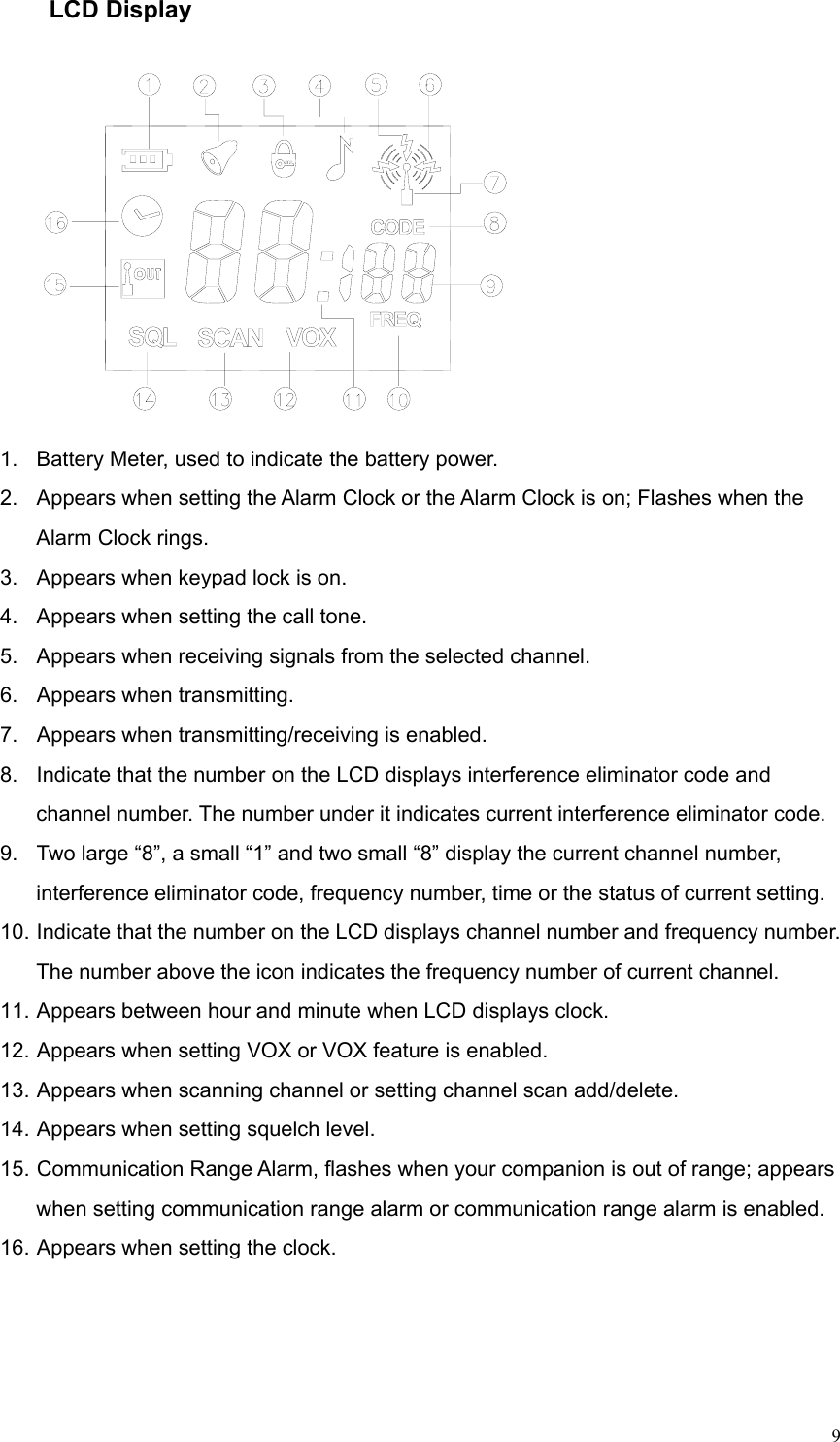
User Manual
Discussion / Help
Navigation