HYT Science and Technology Co TC1688P Two Way Radio User Manual users manaul
Shenzhen HYT Science &Technology; Co Ltd Two Way Radio users manaul
users manaul
1
Forward
Manual Scope
This manual is intended for use by experienced technicians familiar with similar types of
communication equipment. It contains all service information required for the equipment
and is current as of the publication date.
2
Product Safety and RF Exposure for Portable Two-Way Radios
Compliance with RF Energy Exposure Standards
NOTICE: This radio is intended for use in occupational/controlled applications where users have
been made aware of the potential for exposure and can exercise control over their exposure. This
radio device is NOT authorized for general population, consumer or similar use.
BEFORE USING THIS RADIO, READ THE TRAINING MATERIAL BELOW WHICH
CONTAINS IMPORTANT OPERATING INSTRUCTIONS FOR SAFE USAGE AND RF
ENERGY AWARENESS AND CONTROL INFORMATION FOR COMPLIANCE WITH RF
ENERGY EXPOSURE LIMITS IN APPLICABLE NATIONAL AND INTERNATIONAL
STANDARDS.
Federal Communication Commission (FCC) Regulations
The FCC has established limits for safe exposure to radio frequency (RF) emissions from
portable two-way radios. The FCC requires manufacturers to demonstrate compliance
with RF exposure limits before portable two-way radios can be marketed in the U.S. When
two-way radios are approved for occupational/controlled environment exposure limits, the
FCC requires users to be fully aware of, and exercise control over, their exposure.
Awareness and control of RF exposure can be accomplished by the use of labels, or by
education and training through appropriate means, such as information and instructions in
user manuals or safety booklets. Your HYT two-way radio has an RF exposure information
label in the battery compartment. The training material below includes useful information
about RF exposure and helpful instructions on how to control your RF exposure.
Your HYT two-way radio is designed and tested to comply with a number of national and
international standards and guidelines (listed below) regarding human exposure to RF
electromagnetic energy. In terms of measuring RF energy for compliance with FCC
exposure guidelines, your radio radiates measurable RF energy only while it is
transmitting (during talking), not when it is receiving (listening) or in standby mode.
Compliance and Control Guidelines and Operating Instructions for Portable
Two-Way Radios
To control your exposure and ensure compliance with the occupational/controlled
environment exposure limits, always adhere to the following procedures:
* Transmit no more than 50% of the time. To transmit (talk), push the Push-To-Talk (PTT)
button. To receive calls, release the PTT button. Transmitting 50% of the time or less is

3
important since the radio generates measurable RF energy exposure only when
transmitting (in terms of measuring standards compliance).
* Hold the radio in a vertical position in front of the face with the microphone positioned
at least one inch (2.5 cm) away from the lips. Keeping the radio at the proper distance is
important since RF exposure decreases with increasing distance from the antenna.
* For body-worn operation, always use the radio with the HYT Belt-Clip. HYT-approved
accessories, antennas, and device combinations have been tested and comply with the
occupational/controlled environment RF exposure limits. The use of non–HYT approved
accessories may result in exposure levels that may exceed the RF exposure limits for the
occupational/controlled environment.
* If you are not using a body-worn accessory and are not using the radio held in front of
the face, ensure the radio is kept a minimum of 0.7 cm from the body when transmitting.
Keeping the radio at a proper distance is important since RF exposure decreases with
increasing distance from the antenna.
FCC license Information
Your HYT radio operates on communications frequencies which are subject to FCC
(Federal Communications Commission) Rules & Regulations. FCC Rules require that all
operators using Private Land Mobile radio frequencies obtain a radio license before
operating their equipment. Application for license must be made on FCC form 601, and
schedules D, E, and G.
FAX: Forms can be obtained by fax from the FCC Fax-On-Demand system. Call
1-202-418-0177 from your fax machine and request document number 000600 for the
form, schedules, and instructions.
MAIL: Forms can be ordered by telephone, and will be sent to you by first class mail. Call
the FCC Forms Hotline at 1-800-418-FORM (1-800-418-3676).
INTERNET: Form 601 and instructions can be downloaded from the FCC Forms website at:
http://www.fcc.gov/Forms/Form601/601.html
Before filling out your Form 601 application Technical Data section, you must decide
which frequency (or frequencies) you will operate on. Refer to the frequency chart on page
16.
Questions? Call the FCC for license application questions at
1-888-CALL-FCC (1-888-225-5322).

4
Notices to The User
This device complies with Part 15 of the FCC Rules. Operation is subject to the following
two conditions:
(1) this device may not cause harmful interference, and
(2) this device must accept any interference received, including interference that may
cause undesired operation.
One or more of the following statements may be applicable:
FCC WARNING
This equipment generates or uses radio frequency energy. Changes or modifications to this
equipment may cause harmful interference unless the modifications are expressly approved
in the instruction manual. The user could lose the authority to operate this equipment if an
unauthorized change or modification is made.

5
SAFETY INFORMATION:
Your HYT portable two-way radio has been designed using a low power transmitter.
When the PTT switch is pressed, the radio generates radio frequency (RF)
electromagnetic energy (EME). This radio is designed to comply with the FCC Report and
Order
FCC 96-326 (August, 1996).
User Safety Information
The following precautions are recommended for personnel safety:
z DO NOT transmit until all RF connectors are verified secure and any open connectors
are properly terminated.
z SHUT OFF and do not operate this equipment near electrical blasting caps or in an
explosive atmosphere.
z When in vehicles with an airbag, do not place a portable radio in the area over an
airbag or in the airbag deployment area.
z Do not expose the radio to direct sunlight for a long time nor place it close to a heating
source.
z Do not use any portable radio with a damaged antenna. If a damaged antenna comes
into contact with your skin, a minor burn may result.
z This equipment should be serviced by a qualified technician only.
INFORMATION TO THE DIGITAL DEVICE USER REQUIRED BY THE FCC
This equipment has been tested and found to comply with the limits for a Class B digital
device, pursuant to Part 15 of the FCC Rules. These limits are designed to provide
reasonable protection against harmful interference in a residential installation. This
equipment generates, uses and can generate radio frequency energy and, if not installed
and used in accordance with the instructions, may cause harmful interference to radio
communications. However, there is no guarantee that the interference will not occur in a
particular installation. If this equipment does cause harmful interference to radio or television
reception, which can be determined by turning the equipment off and on, the user is
encouraged to try to correct the interference by one or more of the following measures:
• Reorient or relocate the receiving antenna.
• Increase the separation between the equipment and receiver.
• Connect the equipment to an outlet on a circuit different from that to which the receiver is
connected.
• Consult the dealer for technical assistance.
6
Contents
Brief Introduction
LCD Display
Software Description
Circuit Description
CPU Pins
Adjustment Description
Part List 1
Assembly and Disassembly for Repair
Exploded View
Part List 2
Packing
TC1688P PC Board View
TC1688P Block Diagram
TC1688P Schematic Diagram
Specifications
7
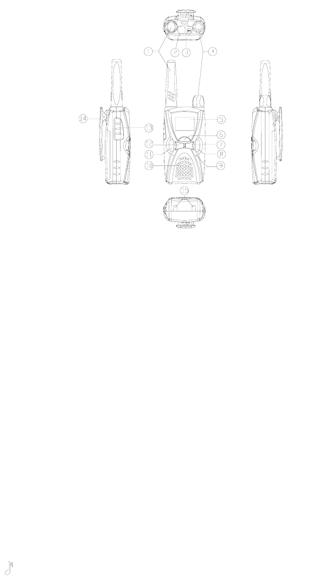
Brief Introduction
1. Antenna
2. Programming Jack
3. Speaker/Mic Jack
4. Power/Volume Knob
Rotate the Power/Volume Knob clockwise until a “click” is heard to turn the radio on, fully
counter clockwise to turn the radio off. When the radio is on, turn the knob to adjust
volume.
5. LCD Display
Indicate operation status of the radio. (Refer to “LCD Display” for details)
6. MENU key
In standby mode, briefly press MENU key to display current channel information and hold
down this key to enter menu mode. During setting, press MENU key to save and switch to
the next setting.
7. “-” key
Used to select the channel/interference eliminator code downwards or change menu
settings.
8. MON key
In standby mode, briefly press MON key to begin channel scanning; hold down MON key
to begin monitoring.
9. MIC
10. Speaker
11. “ ”key (CALL key)
If Call feature is enabled, briefly press the CALL key to transmit a call signal; During
setting, press CALL key to save and return to the first setting or exit; Hold down the CALL
key to lock/unlock keypad.
12. “+” key
8
Used to select the channel/interference eliminator code upwards or change menu
settings.
13. PTT button
Press and hold PTT, radio operates in transmit mode. Release PTT, radio returns to
receive mode.
14. Belt Clip
Used to clip radio on your belt.
15. Charging Connectors
Connect the charging connectors with that on the charger to begin charging.
9
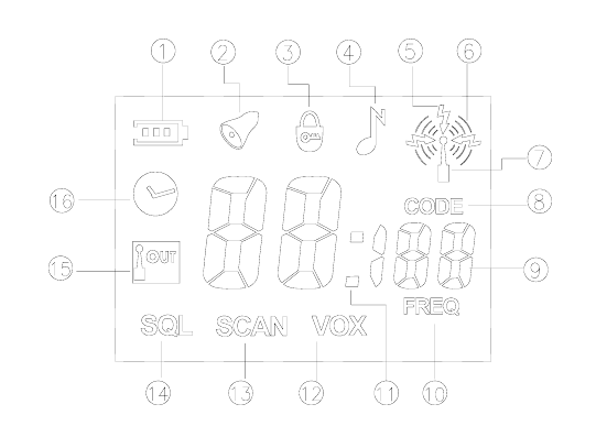
LCD Display
1. Battery Meter, used to indicate the battery power.
2. Appears when setting the Alarm Clock or the Alarm Clock is on; Flashes when the
Alarm Clock rings.
3. Appears when keypad lock is on.
4. Appears when setting the call tone.
5. Appears when receiving signals from the selected channel.
6. Appears when transmitting.
7. Appears when transmitting/receiving is enabled.
8. Indicate that the number on the LCD displays interference eliminator code and
channel number. The number under it indicates current interference eliminator code.
9. Two large “8”, a small “1” and two small “8” display the current channel number,
interference eliminator code, frequency number, time or the status of current setting.
10. Indicate that the number on the LCD displays channel number and frequency number.
The number above the icon indicates the frequency number of current channel.
11. Appears between hour and minute when LCD displays clock.
12. Appears when setting VOX or VOX feature is enabled.
13. Appears when scanning channel or setting channel scan add/delete.
14. Appears when setting squelch level.
15. Communication Range Alarm, flashes when your companion is out of range; appears
when setting communication range alarm or communication range alarm is enabled.
16. Appears when setting the clock.

10
Software Description
Radio Feature Description
Feature Description
1 56 UHF frequencies available Frequency Range: 461 – 470 MHz
2 Selectable number of available
channels 1-8
User can select 1-8 frequencies from 56
available frequencies
3 Selectable 121 Interference Eliminator
Codes
Include 38 CTCSS and 83 CDCSS
4 LCD Display Display operation status and setting
modes
5 LCD Backlight
6 Keypad Lock Pressing any key is invalid except PTT,
briefly pressing MENU key and holding
down CALL key.
7 VOX Feature Only available when connected with
external audio accessory.
8 Five VOX Sensitivity Levels Available The lower the level, the higher the
sensitivity.
9 Battery Power Indicator
10 Low Battery Alert The radio will sound alert when the
battery voltage is lower than preset
threshold value.
11 Channel Scan The radio will only scan the selected 1-8
channels. If 4 channels are selected, the
radio will scan these 4 channels only.
12 Battery Save (Sleep Mode) The radio will enable battery save
feature if no button is pressed and no
operation takes place within 25 seconds.
The radio will switch between 200ms
standby mode and 600ms sleep mode.
13 Clock Display and Alarm Clock
14 Five CALL TONES available The radio will sound call tone when
receiving a valid call. User can disable
the call tone.
15 PC Programmable In this mode, MCU is connected with PC
via UART port.
16 Enable/Disable Certain Features
(through PC programming)
17 Wired Clone MCU transfer the data in one radio to
another via UART port.
18 Monitor
19 Time Out Timer TOT time: 1 minute or 5 minutes. This
feature can be disabled.
20 Auto Squelch 4 squelch levels available. Higher
squelch level makes it harder for the
radio to receive weak signals
21 Communication Range Alarm The radio will sound alert when you are
almost out of communication range.
11
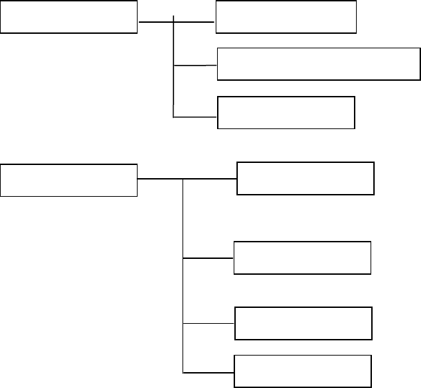
Radio Modes
Functions and Operations
1. Conventional Mode
Turn the power on. If no key is pressed, the radio will enter conventional mode. In this
mode, you can operate as following:
z Receive or press PTT to transmit;
z Display clock (It’s set by your dealer) or channel number;
z Low battery detect and battery power indication;
z VOX feature (Only valid when connecting with external audio accessory) (It’s set by
your dealer);
z Communication Range Alarm (It’s set by your dealer);
z Alarm Clock (It’s set by your dealer);
z Briefly press CALL key to transmit a CALL (It’s set by your dealer);
z Press and hold CALL key to enable/disable keypad lock (It’s set by your dealer);
z Briefly press MENU key to display current channel information (frequency number
and interference eliminator code); Press and hold MENU key to enter setting menu;
z Press UP/DOWN key to increase/decrease channel number;
z Briefly press MONI key to enter channel scan mode; Press and hold MONI key to
begin monitor;
z Battery Save feature (It’s set by your dealer).
User Mode Conventional Mode
Clock and Alarm Clock Setting Mode
MENU Mode
Dealer Mode Channel Setting Mode
PC Programming Mode
Wired Clone Mode
Default Setting Mode

12
2. Clock and Alarm Clock Setting Mode
Turn the power on while holding down CALL key and PTT key simultaneously. After 2
seconds, the radio enters clock and alarm clock setting mode.
Press UP/DOWN to select upwards/downwards. Press MENU key to save and go to next
setting item. Press CALL key to save and go to the first setting item. If the current item is
the first setting item, press CALL key to save and exit.
In this mode, you can operate as following:
z Select to display clock or channel number in conventional mode;
z Set hour of the clock;
z Set minute of the clock;
z Alarm clock enable/disable setting;
z Set hour of the alarm clock;
z Set minute of the alarm clock.
3. Menu Mode
In conventional mode, press and hold down MENU key to enter menu mode.
Press UP/DOWN to select upwards/downwards. Press MENU key to save and go to next
setting item. Press CALL key to save and go to the first setting item. If the current item is
the first setting item, press CALL key to save and exit.
In menu mode, LCD displays “ ” icon indicating that you can transmit/receive. LCD
displays channel information when pressing PTT to transmit. And the display returns to
the setting mode before transmission when releasing PTT or time out timer is due.
In this mode, you can operate as following:
z VOX feature enable/disable and five sensitivity levels setting (It’s set by your dealer);
z Call tone setting (five call tones) (It’s set by your dealer);
z Button beep enable/disable (It’s set by your dealer);
z Squelch level setting;
z Communication rang alarm feature enable/disable (It’s set by your dealer);
z Battery type setting.
4. Channel Setting Mode
Turn the power on while holding down MON and PTT key simultaneously. After 2 seconds,
the radio enters channel setting mode.
Press UP/DOWN to select upwards/downwards. Press MENU key to save and go to next
setting item. Press CALL key to save and go to the first setting item. If the current item is
13
the first setting item, press CALL key to save and exit.
In this mode, you can operate as following:
z Select channel number from 1 to 8;
z Select frequency number from 1 to 56;
z Select interference eliminator code from 0 to 121;
z Set the number of available channels from 1 to 8;
z Scan Add/Delete.
5. PC Programming Mode
Insert programming cable into the programming jack and then turn the power on, the radio
enters PC programming mode.
6. Wired Clone Mode
Connect the radio with wired clone cable and then turn the power on while holding down
CALL and MON key simultaneously, the radio enters wired clone mode after 2 seconds.
And then press MON key to begin data transmission.
7. Default Setting Mode (It’s set by your dealer)
Turn the power on while holding down “+” and “-“ key simultaneously to restore the factory
settings after 2 seconds.
14
Circuit Description
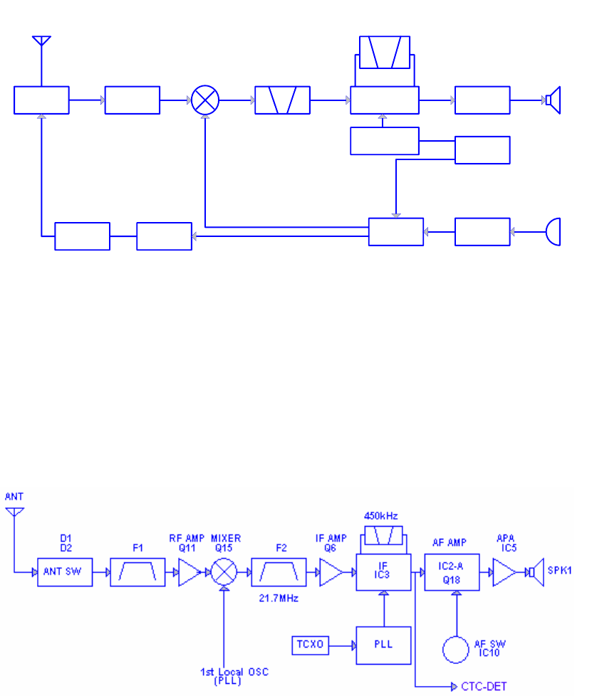
1. Frequency Configuration
The receiver utilizes double conversion. The first IF is 21.7 MHz and the second is 450
KHz. The first local oscillator signal is supplied from PLL circuit. PLL circuit in the
transmitter generates the necessary frequencies. Figure 1 shows the frequency
configuration.
Frequency range: TC1688P: 460—470MHz
(Please refer to “appendix1: TC1688P frequency chart” for more details.)
1 2 3 4
A
B
C
D
4
321
D
C
B
A
Title
Number RevisionSize
B
Date: 4-Feb-2004 Sheet of
File: D:\RPV599A V2.0\material\TC-168~2.DDBDrawn By:
ANT
ANTSW RF AMP
MCF
21.7MHz
CF
450KHz
SYSTEM AF AMP SP
IF
TCXO 21.25MHz
MIC
MIC AMP
PLL
VCO
RX
TX
TX AMP
PA AMP
PLL
Fig1. Frequency Configuration
2. Receiver
The receiver utilizes double conversion super heterodyne.
1) Front-end RF Amplifier
The signal from the antenna passes through a transmit/receive switch circuit
before entering the SAW filter F1 to eliminate unwanted signals, and then is
amplified at RF amplifier Q11. The resulting amplified signal then goes to the first
mixer.
Fig.2 Receiver Section Configuration
15
2) First Mixer
The signal from RF amplifier is mixed with the first local oscillator signal from PLL
frequency synthesizer in the first mixer Q15 to generate a 21.7 MHz first IF signal. The
first IF signal is then fed through the 21.7MHz crystal filter F2 to remove spurious signals
from adjacent channel.
3) IF Amplifier
The first IF signal is amplified at Q6 and then enter the IF process chip IC3. The signal is
mixed with the second local oscillator signal to generate a 450KHz second IF signal. The
second IF signal is then fed to a 450 KHz ceramic filter F3 to eliminate unwanted signals
before it is amplified and detected at IC3.
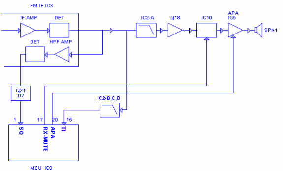
4) AF Amplifier
The AF signal obtained from IC3 is filtered in IC2-A, and then amplified in Q18. Then
resulting AF signal passes through an AF squelch switch IC10 and a volume control circuit
and then is amplified in an AF power amplifier IC5 to drive the speaker.
5) Squelch
Part of the AF signal from IC3 enters IC3 again and the noise component is amplified by a
filter and an amplifier, and then enters Q21 to amplify the noise further. After rectified and
filtered by D7 and C94, the DC signals goes to the analog port IC8 of the microprocessor.
IC8 determines whether to output sounds from the speaker by detecting whether the input
voltage is higher or lower than the preset value.
To output sounds from the speaker, IC8 sends a mute and an AF control signal APA-EN to
IC5. (See figure 3)
Fig. 3 AF amplifier and squelch circuit
16
6) Receiving CTCSS/CDCSS signal
300Hz-and-higher audio frequency of the signal output from IC3 is filtered by low-pass
filter IC2-B, C,D. The resulting signal TI enters the microprocessor IC8. IC8 determines
whether the CTCSS/CDCSS matches the pre-set value, and controls the RX-MUTE, APA
and the speaker output sounds according to the squelch result.
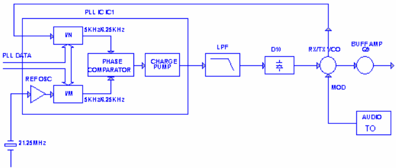
3. PLL Synthesizer
PLL circuit generates the first local oscillator signal for reception and the RF
signal for transmission.
1) PLL circuit
The step frequency of PLL circuit is 5 KHz or 6.25 KHz. A 21.25MHz reference oscillator
signal is divided at IC1 by a mixed counter to create a 5 KHz or 6.25 KHz reference
frequency. Output signal from VCO enters the 16 pin of IC1 and is divided at IC1 by a
dual-module programmable counter. The divided signal is compared in the phase
comparator IC1 with a 5 KHz or 6.25 KHz reference signal. The signal from phase
comparator is filtered through a low-pass filter and generates a VCO voltage adding to
varicap diodes D10 to control the oscillator frequency. (See Figure 4)
Fig.4 PLL Circuit
2) VCO
Q4 composes Colpitts oscillator circuit together with the outside circuit. The oscillator
frequency is controlled by PLL. In receive mode, the oscillator frequency is the first local
oscillator frequency for reception. In transmit mode, the oscillator frequency is the RF
frequency for transmission.
17
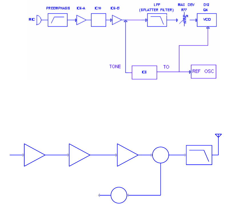
4. Transmitter
1) Transmitting AF
The AF signal from the microphone passes through a pre-emphasis circuit, is amplified
and filtered by a low-pass filter at IC6-A, B, Q5 and Q7. The resulting signal enters VCO
for direct modulation. (See figure 5)
2) CTCSS/CDCSS Encoder
The necessary signal for 38 CTCSS and 83 CDCSS encoder is generated by TO pin of
IC8 and FM-modulated to the PLL reference signal. Since the reference OSC does not
modulate the loop characteristic frequency or higher, modulation is performed at the VCO
side by adjusting the balance. (See fig.5)
Fig 5.Transmit AF and CTCSS/CDCSS
3) RF Amplifier
The RF signal obtained from VCO buffer amplifier is amplified by Q9. The amplified signal
is amplified by power amplifier Q3, Q8 and Q10 to generate RF power. (See Fig.6)
B
CC
B
AMP
Q3
DRIVE AMP
Q8
FINAL AMP
Q10
ANT SW
D1 LPF
ANT
ANT SW
D2
RX
Fig.6 Final Module
4) Antenna Switch and LPF
The RF signal is passed through a low-pass filter network and a transmit/receive switch
(D1 and D2) before it is passed to the antenna terminal. D1 is turned on in transmit mode
and off in receive mode.
18
5. Power Supply
IC4 supply stabilized power for the control circuit. In transmit mode, IC9 is turned on and
supply voltage for the transmit VCO; Q2 is turned on and supply operation voltage for the
transmitting front-end amplifier. In receiving mode, IC9 is turned on and supply voltage for
the receive VCO high-frequency amplified circuit; Q1 is turned on and supply operation
voltage for the receiving circuit.
6. Control System
The IC8 CPU operates at 4.9152MHz and supply control signal voltage for the control
circuit.

19
Appendix 1: Frequency Chart (Initialization)
Frequency No. Frequency (MHz) Frequency No. Frequency (MHz)
1 464.5000 29 462.9125
2 464.5500 30 464.4875
3 467.7625 31 464.5125
4 467.8125 32 464.5375
5 467.8500 33 464.5625
6 467.8750 34 466.0375
7 467.9000 35 466.0625
8 467.9250 36 466.0875
9 461.0375 37 466.1125
10 461.0625 38 466.1375
11 461.0875 39 466.1625
12 461.1125 40 466.1875
13 461.1375 41 466.2125
14 461.1625 42 466.2375
15 461.1875 43 466.2625
16 461.2125 44 466.2875
17 461.2375 45 466.3125
18 461.2625 46 466.3375
19 461.2875 47 466.3625
20 461.3125 48 467.7875
21 461.3375 49 467.8375
22 461.3625 50 467.8625
23 462.7625 51 467.8875
24 462.7875 52 467.9125
25 462.8125 53 469.4875
26 462.8375 54 469.5125
27 462.8625 55 469.5375
28 462.8875 56 469.5625

20
Appendix 2: CTCSS Table
Display
Number
Frequency(Hz) Display Number Frequency(Hz)
1 67.0 20 131.8
2 71.9 21 136.5
3 74.4 22 141.3
4 77.0 23 146.2
5 79.7 24 151.4
6 82.5 25 156.7
7 85.4 26 162.2
8 88.5 27 167.9
9 91.5 28 173.8
10 94.8 29 179.9
11 97.4 30 186.2
12 100.0 31 192.8
13 103.5 32 203.5
14 107.2 33 210.7
15 110.9 34 218.1
16 114.8 35 225.7
17 118.8 36 233.6
18 123.0 37 241.8
19 127.3 38 250.3

21
Appendix 3: CDCSS Table
Display
Number
CDCSS Display Number CDCSS
39 023 82 331
40 025 83 343
41 026 84 346
42 031 85 351
43 032 86 364
44 043 87 365
45 047 88 371
46 051 89 411
47 054 90 412
48 065 91 413
49 071 92 423
50 072 93 431
51 073 94 432
52 074 95 445
53 114 96 464
54 115 97 465
55 116 98 466
56 125 99 503
57 131 100 506
58 132 101 516
59 134 102 532
60 143 103 546
61 152 104 565
62 155 105 606
63 156 106 612
64 162 107 624
65 165 108 627
66 172 109 631
67 174 110 632
68 205 111 654
69 223 112 662

22
70 226 113 664
71 243 114 703
72 244 115 712
73 245 116 723
74 251 117 731
75 261 118 732
76 263 119 734
77 265 120 743
78 271 121 754
79 306
80 311
81 315

23
CPU Pins
Pin No. Pin Name I/O Description
1 SQ I Squelch detect input
2 EXT-PTT I External Mic PTT detect pin
3 TIBI I
CTCSS/CDCSS external circuit central point
input
4 TI I CTCSS/CDCSS signal input
5 NC -
6 NC -
7 CNVSS
8 RESET I Reset detect pin
9 XOUT2 O
10 XIN2 I
Auxiliary oscillator pin, connected with
32.768KHz crystal
11 VSS CPU Ground
12 XIN1 I
13 XOUT1 O
Master oscillator pin, connected with
4.9152MHz crystal
14 VCC CPU main power supply
15 VCO-CTRL O VCO power supply control
16 RX-CTL O Receiving circuit power supply control
17 RX-MUTE O Receiving tone output control
18 TONE O TONE output pin
19 TX-CTL O Transmit circuit power supply control
20 APA-EN O AF power amplifier power control
21 MIC-EN O MIC Enable
22 LED2 O
23 LED1 O
LED control
24 COM1 O
25 COM2 O
26 COM3 O
27 COM4 O
LCD COM control

24
28 VL3
29 VL2
30 VL1
Not connected.
31 SEG12 O
32 SEG11 O
33 SEG10 O
34 SEG9 O
35 SEG8 O
36 SEG7 O
37 SEG6 O
38 SEG5 O
39 SEG4 O
40 SEG3 O
41 SEG2 O
42 SEG1 O
SEG1-SEG12 is LCD SEG control
43 FILT-CTL O CTCSS/CDCSS LPF control
44 PLL-EN O PLL enable
45 PLL-CLK O PLL serial clock
46 PLL-DATA O PLL serial data
47 ST-CTL O VOX side-tone control
48 KEY-OUT2 O
49 KEY-OUT1 O
50 KEY-IN3 I
51 KEY-IN2 I
52 KEY-IN1 I
Keypad signal input output pin
53 EEP-DATA I/O EEPROM serial data
54 EEP-CLK O EEPROM serial clock
55 TXD O RS232 Transmit
56 RXD I RS232 Receive

25
57 NC -
58 TO O CTCSS/CDCSS signal output
59 POW-DET I Power switch detect input
60 EXT-MIC I External Mic detect pin
61 AVSS GND input pin for A-D converter. Connect to
VSS.
62 VREF I Reference power supply input
63 BAT-DET I Battery voltage detect input
64 VOX-DET I VOX signal input

26
Adjustment Description
Before the adjustment, please beforehand save the user’s setting.
Required Test Instrument
1. Stabilized power supply 1set
1) The supply voltage can be changed between 2V and 6V DC, and the output
current is 2A or more;
2) The standard output voltage is 3.6V DC;
3) The power supply output voltage stabilizes.
2. Ammeter 1 set
3. Digital Voltmeter 1 set
4. Radio Communication Test Set 1 set
Test and Adjustment
1. Setting: Put the main unit under test on the jig (Note: Make sure the test terminal
and the jig connect well), and turn on the power.
2. VCO
Enable “Default Set Mode” function in programming software. And then press “+”, “-”
and “MENU” keys simultaneously to turn on the radio and enter adjustment mode.
Measurement Adjustment
Item Condition Test
Instrument Terminal Parts Method
Specification/
Remarks
Transmit
VCO lock
voltage
CH1:
Transmitting
Digital
Voltmeter P6 L22
Adjust L22 using
ceramic
screwdriver until
the lock voltage
reaches the
selected range
2.5±0.1V
Receive
VCO lock
voltage
CH1:
Receiving
Digital
Voltmeter P6 L22 Check Around 1.0V
3. Receiver
Measurement Adjustment
Item Condition
Test Instrument Terminal Parts Method Specification/Remarks
RX IF
demodulation
output
A
djust to CH1.
Press MON for
1 second to
receive.
Radio
Communication
Test Set SSG:
-60dB
MOD: 1KHz,
DEV: 1.5KHz
FILTER:
0.3~3KHz
Antenna
Mic jack L20
Adjust L20
using ceramic
screwdriver
until the max.
AF output
signal
appears.
When adjusting,
rotate the volume
control to the right
position so that the
output won’t limit.

27
Measurement Adjustment
Item Condition Test
Instrument Terminal Parts Method Specification/Remarks
R
eceiving
S
ensitivity
Adjust to
CH1. Press
MON for 1
second to
receive.
Radio
Communication
Test S e t
SSG:
-119dBm,
MOD:1KHz
DEV: 1.5KHz
FILTER:
0.3~3KHz
Antenna
Mic jack
Check
SINAD:
12dB or higher
Adjust to CH1
and set SQ as
level 1
Radio
Communication
Test Set SSG:
-119dBm,
Squelch level:
-122±1.5dB
Squelch
Adjust to CH1
and set SQ as
level 4
Radio
Communication
Test S e t
SSG:
-110dBm,
Antenna
Mic jack
Reduce the
SSG output
signal
gradually until
AF output
mutes.
Squelch level:
-114±1.5dB
4. Transmitter (Be sure to connect the antenna or dummy load before adjustment)
Measurement Adjustment
Item Condition
Test Instrument Terminals Parts Method Specification/Remarks
±2.5ppm
Transmitting
Frequency
Radio
Communication
Test S e t
VC1
Use ceramic
screwdriver to
adjust VC1 so
that the center
frequency is no
more than the
error.
Transmitting
power
Adjust to CH1.
Press PTT to
transmit.
Radio
Communication
Test Set
Ammeter
Antenna
Check
≥700mW
Max
frequency
deviation
Adjust to CH1.
Press PTT to
transmit.
Radio
Communication
Test Set
LPF: 15KHz
AF OUT:
1KHz/150mV
Antenna
Mic Jack R77
Use screwdriver
to adjust R77 so
that frequency
deviation is in the
regulated range.
Frequency deviation:
2.1KHz~2.2KHz
Modulation
Sensitivity
Adjust to CH1.
Press PTT to
Radio
Communication
Antenna
Mic Jack Check
Frequency deviation:
1.1KHz~1.8KHz

28
transmit. Test S e t
BPF:0.3~3KHz
AF OUT:
1KHz/12mV
Adjust to CH2
and CTCSS
code
automatically
turns to “1”.
Press PTT to
transmit.
Radio
Communication
Test S e t
LPF:0.3KHz
Antenna
Use screwdriver
to adjust R153
and R152 so that
CTC frequency
deviation is in the
regulated range.
Frequency deviation:
0.45±0.05KHz
Adjust to CH3
and CTCSS
code
automatically
turns to “38”.
Press PTT to
transmit.
Radio
Communication
Test S e t
LPF:0.3KHz
Antenna Check
Frequency deviation:
0.45±0.05KHz
CTCSS
/CDCSS
Frequency
Deviation
Adjust to CH4;
automatically
turn to
CDCSS. Press
PTT to
transmit.
Radio
Communication
Test S e t
LPF:0.3KHz
Antenna Check
Frequency deviation:
0.5±0.1KHz
Set the battery
as A
Adjust power
supply output
voltage and check
alert level
3.3±0.1V
Low Battery
Alert Level
Set the battery
as n
Digital Voltmeter Power
supply port
Power
supply Adjust power
supply output
voltage and check
alert level
3.1±0.1V
Set the battery
as A
Adjust power
supply output
voltage and check
power off level
3.1±0.1V
Low Battery
Power-off
Level Set the battery
as n
Digital Voltmeter Power
supply port
Power
supply Adjust power
supply output
voltage and check
power off level
3.0±0.1V
5. After adjustment, recover the original setting (before adjustment) of the radio through programming
software.
29
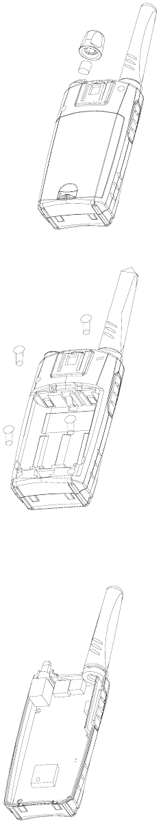
Assembly and Disassembly for Repair
Fig. 1
Remove the power knob. See figure1.
Fig. 2
Remove the four screws on the chassis. See figure 2.
Fig. 3
The disassembled unit is shown as figure 3.
30
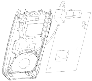
Fig. 4
Take out the antenna spring, antenna cover and PCB. See figure 4.
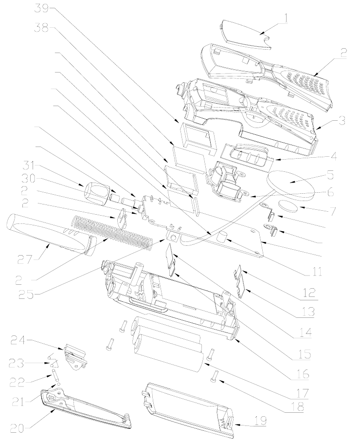
31
Exploded View
6
9
8
32
33
10
8
9
34
35
36
37
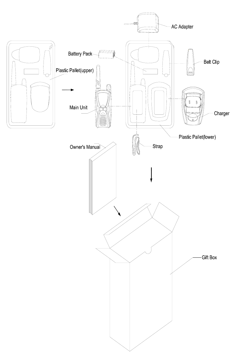
32
Packing

33
Specifications
Frequency Range 460MHz-470MHz
Number of Channels 56 (Max.)
Number of CTCSS 38
Number of CDCSS 83
Frequency Error ≤±2.5PPM
Transmitting Power 1.0W
Radiated Power 0.2W
Transmitter Spurious Emission ≤20uW
Modulation Limitation ±2.5KHz
Bandwidth ≤8.5KHz
Adjacent Channel Power Rejection ≥60dB
Modulation AF Distortion ≤10%
Receiving Sensitivity ≤0.3uV (12dB SINAD)
Co-channel Rejection ≥-8dB
Blocking ≥85dB
Intermodulation Rejection ≥50dB
Adjacent Channel Selectivity ≥50dB
Receiver Spurious Emission ≤2nW
Receiving AF Distortion ≤10%