HYT Science and Technology Co TM-600V Mobile Radio User Manual
Shenzhen HYT Science &Technology; Co Ltd Mobile Radio
UserManual.wiki
>
HYT Science and Technology Co
>
TM 600V User Manual
Users Manual
Navigation menu
Upload a User Manual
Namespaces
Wiki Guide
HTML
PDF
Info
Views
User Manual
Discussion / Help
Navigation
![第 16 页 共 31 页 Basic Operations Radio Power On/Off Press the power switch to turn on the radio. Press and hold down the power switch for about 1 second to turn off the radio. Adjust the Volume Turn the Volume Control Knob clockwise to increase the volume, or counter-clockwise to decrease the volume. Note: 1. If the radio is programmed with CTCSS/CDCSS, 2-Tone signalling squelch, no noise will be heard from the speaker even though at maximum volume level. 2. Holding down the Monitor key (Monitor C/D) simultaneously while adjusting volume level, to hear the current volume level from the speaker. Monitor If the Monitor function is set by your dealer, press the Monitor key (programmable) while in receive mode, to monitor activities on the current channel. The Monitor key is programmable with one of the following four operating modes by your dealer: 1、Monitor Unmute-Momentary Hold down the [MONI] key to open CTCSS/CDCSS/2-Tone signalling squelch. Release to close the signalling squelch. 2、Monitor Unmute-Toggle Press the [MONI] key to open CTCSS/CDCSS/2-Tone signalling squelch. Press again to close the signalling squelch. 3、Carrier Squelch-Momentary Hold down the [MONI] key to open carrier squelch; Release to close the carrier squelch. 4、Carrier Squelch-Toggle Press the [MONI] key to open carrier squelch. Press again to close the carrier squelch. Select a Channel The ▲/▼ or P1-P2 function keys are programmable by your dealer to select a channel.](https://usermanual.wiki/HYT-Science-and-Technology-Co/TM-600V/User-Guide-734944-Page-16.png)
![第 17 页 共 31 页 The Rx/Tx frequency on each channel is set by your dealer. Press the [Channel Up] key (programmable) to select a higher numbered channel; press the [Channel Down] key to select a lower numbered channel. Receive If CTCSS/CDCSS, 2-Tone has been programmed on the current channel by your dealer, you can receive calls with matched tones or codes only. If CTCSS/CDCSS, 2-Tone is not set, you can hear from all the users on the same channel. Transmit 1. Hold down the [PTT]. 2. Dial DTMF number via microphone keypad. (This operation may be unnecessary). 3. Speak into the microphone. The LED is red while calling. 4. Release the [PTT] to return to the receive mode. 5. When transmission ends, put the microphone on hook. Programmable Power Output If the current channel is programmed with high power by your dealer, the power output toggles between high and low upon each press the Tx Power Select key (programmable). Low power is for battery saving and avoiding interference with other users, low power is recommended when communication within limited range. Note: If the current channel is programmed with low power, press the Tx Power Select key, an error alert tone is heard while the power output will not change. If you switch to low power on a channel that was set with high power, this configuration is done on all other channels that were set with high power. BOT ID and EOT ID Your dealer may configure whether to transmit Connect ID (BOT ID) and Disconnect ID (EOT ID), when connecting or disconnecting a repeater or telephone system. The following modes are programmable: 1、BOT ID occurs on each press of [PTT]. EOT ID occurs on each release of [PTT]. 2、Press the [*] while holding down the [PTT], then BOT ID is transmitted. Pres the [#] while holding down the [PTT], then EOT ID is transmitted.](https://usermanual.wiki/HYT-Science-and-Technology-Co/TM-600V/User-Guide-734944-Page-17.png)
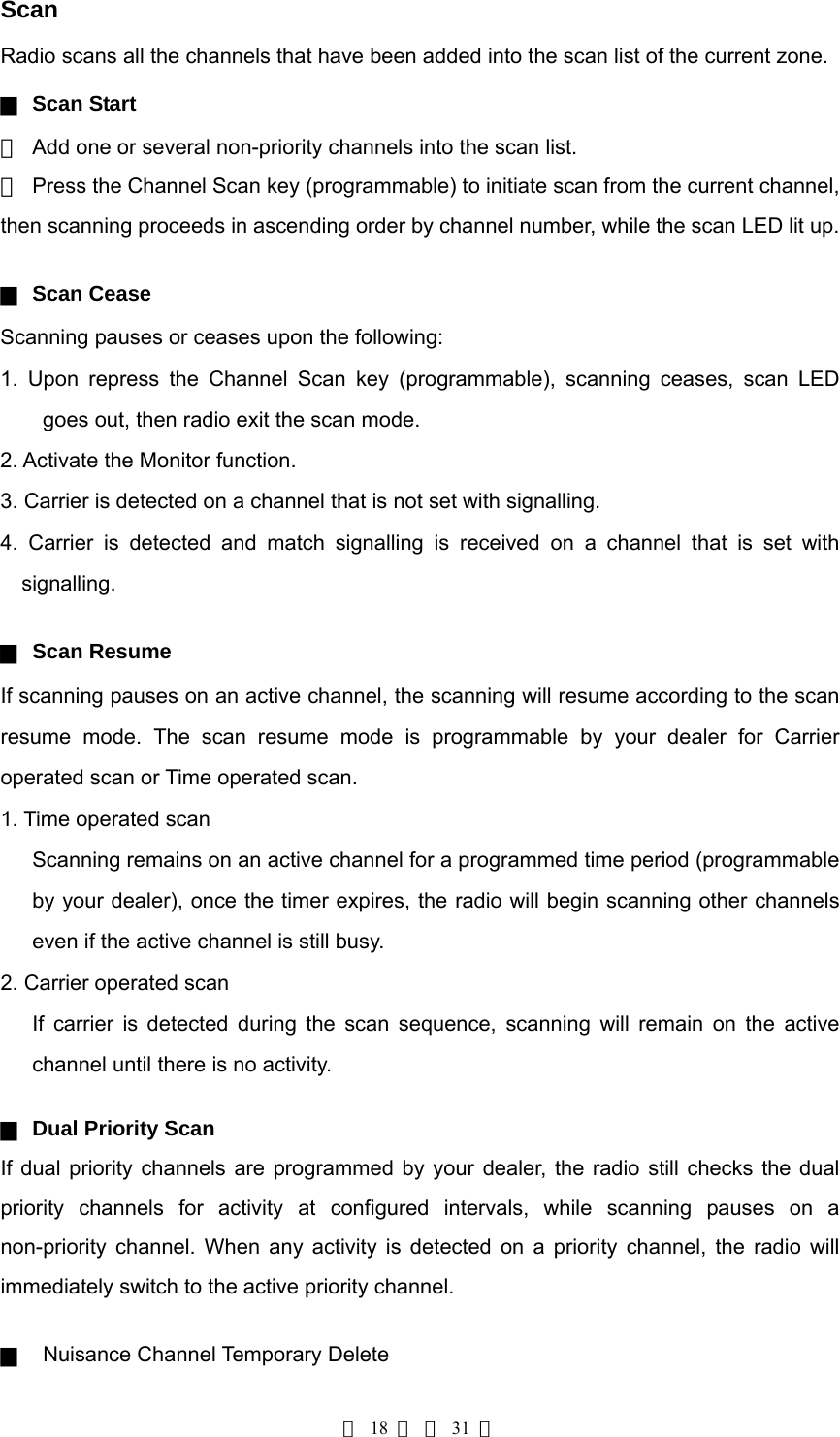
![第 19 页 共 31 页 Temporarily delete the selected channel from the scan list during scanning. When scan pauses on an unwanted channel due to noise, press the Add/Del Scan key (programmable) to temporarily delete the channel from the scan list. Then scan is reactivated immediately. Note: the temporary delete is not memorized once radio exits from the scan mode. ▇ Revert Channel Upon pressing the [PTT] during scanning, the radio will pause scanning and switch to the Revert Channel to transmit. This feature is programmable by your dealer. ▇ Off-Hook Scan If the Off-Hook Scan feature is programmed by your dealer, radio scans no matter the microphone is in the off or on hook condition. Otherwise, microphone must be on hook for scanning. Busy Channel Lockout (BCL) The feature can be enabled/disabled by your dealer, this feature is to prevent transmission on a channel that is already in use. Press the [PTT] on a channel that is already in use, transmission is inhibited and an alert tone is heard. Upon release the [PTT], the alert tone ceases and radio returns to receive mode. Press the [PTT] to transmit while the channel is free. BCL Override If the BCL Override feature is enabled, you can override the BCL feature to transmit on a busy channel. Press the [PTT], a BCL alarm will be heard, then repress the [PTT] within 0.5s to override the BCL feature and transmit on the busy channel. DTMF Call ▇ Manual Dial Press any key from the DTMF keypad of the microphone, while holding down the [PTT], to transmit the DTMF frequency, and the DTMF tone will be heard from the local speaker. Release the [PTT] to remain transmission for 2s (programmable by your dealer), press a numeric key within the 2s to continue transmission. ▇ Keypad Auto PTT This feature is programmable by your dealer. If the feature is enabled, press numeric key to transmit DTMF frequency without pressing the [PTT].](https://usermanual.wiki/HYT-Science-and-Technology-Co/TM-600V/User-Guide-734944-Page-19.png)
![第 20 页 共 31 页 ▇ DTMF Speed 6, 8, 10 or 15 digits per second is programmable by your dealer. The feature is designed to reduce false decoder operation by providing a fixed time period between digits. ▇ Auto Dial 1. Press the [*] on the Mic keypad. 2. Enter the pre-stored DTMF code location number (1~9). 3. LED displays the location number (1.~9.). 4. Press the [PTT] to transmit the stored number. ▇ Redial 1. Press the [*] on the mic keypad. 2. Then press the [0]. 3. LED displays 0. 4. Press the [PTT] to transmit the last dialed number (max. 16 digits). Note: the redial memory is cleared once the radio is turned off. Code Squelch This feature can be enabled/disabled via programming by your dealer. If the feature is enabled, the preset 2-Tone controls radio mute/unmute. The radio will not unmute until matched signalling is received. ▇ Receive 1. Radio is unmuted when matched 2-Tone signalling (programmed by your dealer) is received, the user can hear from the transmitter without any other operation. 2. LED flashes orange. 3. Radio is muted upon press the Monitor key (programmable), or no signal is received within the preset time period. 4. If the Alert Tone is enabled, radio will emit alert when matched signalling is received. If the Transpond is enabled, radio will transpond a signal to the calling radio. However, radio will no transpond if a group call is received. ▇ Transmit 1. Holding down the [PTT]. 2. Enter the preset DTMF encode (radio encode or group encode) via keypad. The further operations are the same as that of normal mobile radios. Red LED lit up while in transmission.](https://usermanual.wiki/HYT-Science-and-Technology-Co/TM-600V/User-Guide-734944-Page-20.png)
![第 21 页 共 31 页 Please refer to the [TTS] key for 2-Tone transmission. 3. Upon release the [PTT], the signalling squelch is disabled and LED flashes orange. Green LED lit up when signal is received. 4. If the Monitor key (programmable) is pressed, or no signal is received within the preset time period, the signalling squelch is enabled. Auto Transpond The Auto Transpond feature can be programmed by your dealer to operate with Code Squelch. If the Auto Transpond feature is enabled, radio will automatically transpond a signal when a call with matched signalling is received. Your dealer may program one type of call response from the following: 1. Alert 2. Transpond 3. Alert & Transpond Press any key to stop transpond. Off Hook Decode If the feature is enabled by your dealer, CTCSS/CDCSS decode signalling is active no matter the microphone is in the off/on hook condition. If the feature is disabled, CTCSS/CDCSS decode signalling is disabled while the microphone is in the off hook condition. Time-out Timer (TOT) ▇ Time-out Timer(TOT) The TOT feature is to prevent user from transmitting on the channel for extended period of time. This also protects the radio from damage caused by long time transmission. Once a continuous transmission exceeds the preset time (15~1200s programmable), the transmission is automatically terminated and alert tone is heard. The alert tone ceases upon release the [PTT]. The TOT default is 180s, it meets normal operation needs. Any change should be permitted by professional technicians. ▇ TOT Pre-alert The radio has a TOT Pre-alert timer. The radio will emit the Pre-alert tone at the programmed time (1~10s before the TOT timer expires).](https://usermanual.wiki/HYT-Science-and-Technology-Co/TM-600V/User-Guide-734944-Page-21.png)
![第 22 页 共 31 页 ▇ TOT Re-key Time The radio has a TOT Re-key timer. Since transmission is terminated upon the TOT timer expires, transmission is inhibited if press the [PTT] before the expiration of TOT Re-key timer (programmable by your dealer as Off, 1~60s). ▇ TOT Reset Time Upon the press of [PTT], “TOT” begins timing. After the release of [PTT], “TOT” reset timer begins timing, However, the TOT timer will not reset until the TOT Reset timer expires. The TOT Reset Time is programmable by your dealer as Off, 1~15s. Emergency Call Holding down the Emergency Call key (programmable as long or short press), the radio will enter the Emergency Call mode and switch to the preset Emergency Channel. The radio will firstly transmit within the preset time period, and then receive within the preset time period, and so does the cycle. The radio will back to the channel before the Emergency Call mode, upon re-holding down the Emergency Call key (programmable as long or short press).](https://usermanual.wiki/HYT-Science-and-Technology-Co/TM-600V/User-Guide-734944-Page-22.png)
![第 23 页 共 31 页 Programmable Auxiliary Functions The [P1]-[P2], ▲/▼ are respectively programmable with one of the following auxiliary functions by your dealer. Reverse Frequency If communications between radios are disrupted because of a long distance from the repeater, the Reverse Frequency function can be used to re-establish communications with another radio. When the function is activated, the transmit frequency and receive frequency will be reversed. The preset CTCSS/CDCSS encoding and decoding signals will also be reversed. Press the Reverse Frequency key (programmable) to toggle the Reverse Frequency function ON or OFF. Talk Around If the Talk Around feature is enabled, the Rx frequency is used in place of the Tx frequency when transmitting, and the CTCSS/CDCSS decoding signal is used in place of the encoding signal when encoding. Press the Talk Around key (programmable) to toggle the Talk Around function ON or OFF. Selectable Squelch Level (SQL) 1、 Upon press the SQL key (programmable), LED displays the current squelch level. 2、 Select the desired squelch level via the programmable key ▲/ ▼. 3、 Upon press the [P1] or [P2] key (programmable), LED resets to the original display mode. Note: High squelch level may cause the radio to ignore weak signals; while low squelch level may cause noise or unwanted signals to be heard. User Selectable CTCSS/DCS(UST) If the UST feature is enabled by your dealer, the user can temporarily change the CTCSS/CDCSS codes that preset on the channel. 1. Select a desired channel. 2. Press the [UST] key (programmable) to enter the UST mode. 3. Use the ▲/ ▼ key to select a desired UST code (the newly selected CTCSS/CDCSS code is valid in the UST mode only), then the CTCSS/CDCSS code on the current channel is set as the selected UST code.](https://usermanual.wiki/HYT-Science-and-Technology-Co/TM-600V/User-Guide-734944-Page-23.png)
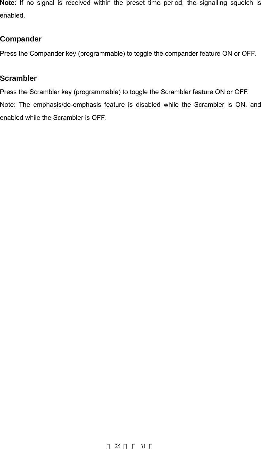
![第 24 页 共 31 页 4. Repress the [UST] key to exit the UST mode, then LED resets to the original display mode. Public Address (PA) The PA feature amplifies audio inputted from the microphone, and the audio can be heard from the external speaker which is connected via 15PIN expansion port. 1. Press PA key (programmable) to activate the PA feature, then the LED displays “P”. Repress the PA key to disable the PA feature, then the radio returns to normal user mode. 2. Once the PA feature is activated, the radio is unable to transmit and receive. 3. Speak into the microphone while holding down the [PTT], your voice can be heard from the external speaker that is connected to the radio. While in PA mode or the PA process initiates, the user can adjust volume via the volume control knob. 4. Release the [PTT] to end PA process, then the radio returns to the PA mode. Note: In PA mode, adjust volume via the volume control knob. While using the PA system, the optional PA accessories and external speaker must be installed by your dealer. Dual Home Channel Upon press the Home Channel key (programmable), the radio will promptly go to the programmed home channel. When dual home channels are set, press the programmed Home Channel key to promptly go to Home Channel 1, press again to promptly go to Home Channel 2, and press for the third time to return to the original channel. 2-Tone Encode Select 1. Press the 2-Tone Encode Select key (programmable), local LED displays the preset 2-Tone encode sequence (0~9). 2. Press the ▲/ ▼ key to select 2-Tone encode (0~9). 3. Holding down the [PTT] to transmit the selected 2-Tone encode. 4. Upon release the [PTT], the signalling squelch is disabled and LED flashes orange. 5. If the Monitor key is pressed, or no signal is received within the preset time period, the signalling squelch is enabled.](https://usermanual.wiki/HYT-Science-and-Technology-Co/TM-600V/User-Guide-734944-Page-24.png)
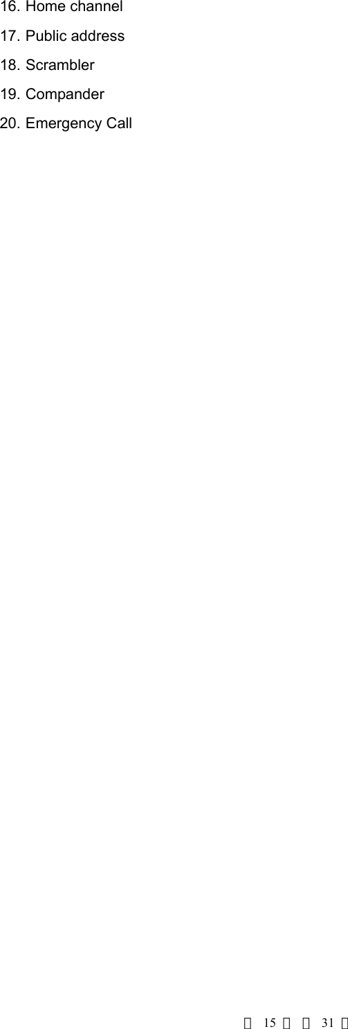
![第 26 页 共 31 页 Key Assignment Programmable function keys [P1]-[P2], ▲/▼. Key Assignment No Function keys Setting Display Remarks 1 [P1] Off 1 CH Number No function CH Up 2 CH Number Channel Up CH Down 3 CH Number Channel Down MONI A 4 CH Number MONI A: Carrier Squelch-momentary MONI B 5 CH Number MONI B: Carrier Squelch-toggle MONI C (default) 6 CH Number MONI C: Squelch off-momentary MONI D 7 CH Number MONI D: Squelch off -toggle User Selectable Tone8 UST Number (0.-9.) CTCSS/DCS Tone Sel 2Tone 9 2Tone Number (0.-9.) Select 2-Tone encode TX power Select 10 CH Number Switch transmit power Scan 11 ● Scan Add/Del 12 ● Temporarily delete nuisance channel Reverse Freq 13 CH Number Reverse frequency Talk Around 14 CH Number Talk Around SEL SQL 15 SQL Number (0.-9.) Select squelch level Home CH 16 HomeCH Number(1-8)Home Channel Public Address 17 P Public address](https://usermanual.wiki/HYT-Science-and-Technology-Co/TM-600V/User-Guide-734944-Page-26.png)
![第 27 页 共 31 页 Scrambler 18 CH Number Scrambler Compander 19 CH Number Compander Emergency Call 20 EmergencyCH Number (1- 8)Emergency call 2 [P2] Off 1 CH Number No function CH Up 2 CH Number Channel Up CH Down 3 CH Number Channel Down MONI A 4 CH Number MONI A: Carrier Squelch-momentary MONI B 5 CH Number MONI B: Carrier Squelch-toggle MONI C 6 CH Number MONI C: Squelch off-momentary MONI D 7 CH Number MONI D: Squelch off -toggle User Selectable Tone8 UST Number (0.-9.) CTCSS/DCS Tone Sel 2Tone 9 2Tone Number (0.-9.) Select 2-tone encode TX Power Select 10 CH Number Switch transmit power Scan (default) 11 ● Scan Add/Del 12 ● Temporarily delete nuisance channel Reverse Freq 13 CH Number Reverse frequency Talk Around 14 CH Number Talk around SEL SQL 15 SQL Number (0.-9.) Select squelch level Home CH 16 HomeCH Number (1- 8) Home channel Public Address 17 P Public address Scrambler 18 CH Number Scrambler](https://usermanual.wiki/HYT-Science-and-Technology-Co/TM-600V/User-Guide-734944-Page-27.png)
![第 28 页 共 31 页 Compander 19 CH Number Compander Emergency Call 20 EmergencyCH Number (1- 8)Emergency call 3 ▲ ( [UP] ) Off 1 CH Number No function CH Up (default) 2 CH Number Channel Up CH Down 3 CH Number Channel Down MONI A 4 CH Number MONI A: Carrier Squelch-momentary MONI B 5 CH Number MONI B: Carrier Squelch-toggle MONI C 6 CH Number MONI C: Squelch off-momentary MONI D 7 CH Number MONI D: Squelch off -toggle User Selective Tone 8 UST Number(0.-9.) CTCSS/DCS Tone Sel 2Tone 9 2Tone Number(0.-9.) Select 2-Tone encode TX Power Select 10 CH Number Switch transmission power Scan 11 ● Scan Add/Delete 12 ● Temporarily delete nuisance channelReverse Freq 13 CH Number Reverse Frequency Talk Around 14 CH Number Talk around SEL SQL 15 SQL Number(0.-9.) Select squelch level Home CH 16 HomeCH Number (1-8) Home channel Public Address 17 P Public address Scrambler 18 CH Number Scrambler Compander 19 CH Number Compander](https://usermanual.wiki/HYT-Science-and-Technology-Co/TM-600V/User-Guide-734944-Page-28.png)
![第 29 页 共 31 页 Emergency Call 20 EmergencyCH Number (1- 8)Emergency Cal 4 ▼( [DOWN] ) Off 1 CH Number No function CH Up 2 CH Number Channel Up CH Down (default)3 CH Number Channel Down MONI A 4 CH Number MONI A: Carrier Squelch-momentaryMONI B 5 CH Number MONI B: Carrier Squelch-toggle MONI C 6 CH Number MONI C: Squelch off-momentary MONI D 7 CH Number MONI D: Squelch off -toggle User Selective Tone 8 UST Number(0.-9.) CTCSS/DCS Tone Sel 2Tone 9 2Tone Number(0.-9.) Select 2-Tone encode TX Power Select 10 CH Number Switch transmission power Scan 11 ● Scan Add/Delete 12 ● Temporarily delete nuisance channelReverse Freq 13 CH Number Reverse Frequency Talk Around 14 CH Number Talk around SEL SQL 15 SQL Number(0.-9.) Select squelch level Home CH 16 HomeCH Number(1-8) Home channel Public Address 17 P Public address Scrambler 18 CH Number Scrambler Compander 19 CH Number Compander mergency Call 20 EmergencyCH Number (1- 8)Emergency Call](https://usermanual.wiki/HYT-Science-and-Technology-Co/TM-600V/User-Guide-734944-Page-29.png)