HYT Science and Technology Co TM-600V Mobile Radio User Manual
Shenzhen HYT Science &Technology; Co Ltd Mobile Radio
Users Manual
第 1 页 共 31 页
THANK YOU!
Thank you for your purchase of HYT mobile radio TM-600. We believe this
easy-to-use radio will provide you with dependable and reliable
communications at peak efficiency. Please read this manual carefully before
use. The information presented herein will help you to derive maximum
performance from your radio.
MODELS COVERED IN THIS MANUAL
TM-600 VHF Mobile Radio
TM-600 UHF Mobile Radio

第 2 页 共 31 页
HOT SURFACE
Avoid contact during prolonged use
Do not touch the metal surface of the radio while it is in use.
Do not mount the radio such that the chassis can come in contact with skin.
High temperatures may burn you skin.
MANDATORY SAFETY INSTRUCTIONS TO INSTALLERS AND USERS
════════════════════════════════════════════════════════════════
● Use Only manufacturer or dealer supplied antennas.
● Antenna minimum safe distance: 100 cm
● Antenna used for this transmitter must not exceed an antenna gain of 3dBi (for VHF)
and 5.5dBi (for UHF).
The FCC (Federal Communications Commission) has adopted a safety standard for
human exposure to RF energy which is below the OSHA (Occupational Safety and Health
Act) limits.
● Antenna mounting: The antenna supplied by the manufacturer or radio dealer must not
be mounted at a location such that during radio transmission, any person can come closer
than the above indicated minimum safe distance to the antenna (i.e. 100 cm).
● To comply with current FCC RF Exposure limitations, the antenna must be installed at or
exceeding the minimum safe distance indicated above, and in accordance with the
requirements of the antenna manufacturer or supplier.
● Vehicle installation: The antenna can be mounted at the center of a vehicle metal roof or

第 3 页 共 31 页
trunk lid if the minimum safe distance is observed.
Antenna substitution: Don’t substitute any antenna for the one supplied or recommended
by the manufacturer or radio dealer. You may be exposing person(s) to excessive radio
frequency radiation. You may contact your radio dealer or the manufacturer for further
instructions.
Warning
Maintain a separation distance from the antenna to person(s) at least 100 cm .
“This transmitter is authorized to operate with a maximum duty factor of 50%, in a typical
push-to-talk mode, for satisfying FCC RF exposure compliance requirements.”
第 4 页 共 31 页
Contents
Caution
MANDATORY SAFETY INSTRUCTIONS
User Safety, Training, and General Information
Compliance with RF Energy Exposure Standards
FCC Compliance
Precautions
Product Inspection
Radio Installation and Warnings
Radio Overview
Basic Operations
Radio Power On/Off
Adjust the Volume
Monitor
Select a Channel
Receive
Transmit
Programmable Power Output
BOT ID and EOT ID
Scan
Busy Channel Lockout(BCL)
BCL Override
DTMF Call
Code Squelch
Auto Transpond
Off Hook Decode
Time-out Timer (TOT)
Emergency Call
Programmable Auxiliary Functions
Reverse Frequency
Talk Around
第 5 页 共 31 页
Selectable Squelch Level
User Selectable CTCSS/DCS(UST)
Public Address(PA)
Dual Home Channel
2-Tone Encode Select
Compander
Scrambler
Optional Accessories
第 6 页 共 31 页
User Safety, Training, and General Information
READ THIS IMPORTANT INFORMATION ON SAFE AND EFFICIENT OPERATION
BEFORE USING YOUR HYT MOBILE RADIO.
Compliance with RF Energy Exposure Standards
Your HYT mobile radio is designed and tested to comply with a number of national and
international standards and guidelines (listed below) regarding human exposure to radio
frequency electromagnetic energy. This radio complies with the IEEE and ICNIRP
exposure limits for occupational/controlled RF exposure environment at operating duty
factors of up to 50% transmitting and is authorized by the FCC for occupational use only.
In terms of measuring RF energy for compliance with the FCC exposure guidelines, your
radio radiates measurable RF energy only while it is transmitting (during talking), not when
it is receiving (listening) or in standby mode.
Your HYT mobile radio complies with the following of RF
energy exposure standards and guidelines:
z United States Federal Communications Commission, Code of Federal
Regulations; 47CFR part 2 sub-part J
z American National Standards Institute (ANSI)/Institute of Electrical and Electronic
Engineers (IEEE) C95. 1-1992
z Institute of Electrical and Electronic Engineers (IEEE) C95. 1-1999 Edition
z International Commission on Non-Ionizing Radiation Protection (ICNIRP) 1998
Operational Instructions and Training Guidelines
To ensure optimal performance and compliance with the occupational/controlled
environment RF energy exposure limits in the above standards and guidelines, users
should transmit no more than 50% of the time and always adhere to the following
procedures:
Transmit and Receive
To transmit (talk), push the Push-To-Talk (PTT) button; to receive, release the PTT button
第 7 页 共 31 页
FCC Compliance
Part 15 Compliance
This equipment has been tested and found to comply with the limits for a Class B digital
device, pursuant to part 15 of the FCC Rules. These limits are designed to provide
reasonable protection against harmful interference in a residential installation. This
equipment generates, uses and can radiate radio frequency energy and, if not installed
and used in accordance with the instructions, may cause harmful interference to radio
communications. However, there is no guarantee that interference will not occur in a
particular installation. If this equipment does cause harmful interference to radio or
television reception, which can be determined by turning the equipment off and on, the
user is encouraged to try to correct the interference by one or more of the following
measures:
Reorient or relocate the receiving antenna.
Increase the separation between the equipment and receiver.
Connect the equipment into an outlet on a circuit different from that to which the
receiver is connected.
Consult the dealer or an experienced radio/TV technician for help.
FCC Licensing Requirements
Your radio must be properly licensed Federal Communications Commission prior to use.
Your HYT Wireless dealer can assist you in meeting these requirements. Your dealer will
program each radio with your authorized frequencies, signalling codes, etc., and will be
there to meet your communications needs as your system expands.
Precautions
General Safety Standards
* Do not attempt to configure the radio while driving; it is too dangerous.
* Do not operate your radio when someone is either touching the antenna or standing
within 2 or 3 feet of it, to avoid the possibility of radio frequency burns or related physical
injury.
* Do not operate the radio near dynamite blasting caps or in an explosive atmosphere.
* Switch OFF the radio while refueling or parking at gas station.
* Turn off your radio in any place where posted notices instruct you to do so.
* Do not modify the radio for any reason.
第 8 页 共 31 页
* Do not expose the radio to direct sunlight over a long time, nor place it close to heating
source.
* Do not place the radio in excessively dusty, humid areas, nor on unstable surfaces.
* Refer service to qualified technicians only.
Operation Safety Guidelines
* For vehicles equipped with electronic anti-skid braking systems, electronic ignition
systems or electronic fuel injection systems, interferences may occur during the radio
transmission. If the foregoing electronic equipments are installed on your vehicle,
please contact your dealer for further assistance to make sure that the radio
transmission will not interfere with these equipments.
* For radio installation in vehicles fueled by LP gas with LP gas container within interior of
the vehicles, the following precautions are recommended for personal safety.
(1) Any space containing radio equipment shall be isolated by a seal from the space in
which the LP gas container and its fittings are located.
(2) Remote (outside) fitting connections shall be used.
(3) Good ventilation is required for the container space.
Safety: It is important that the operator is aware of, and understands, hazards common
to the operation of any radio.
Installation Safety Guidelines
* Do not mount the mobile radio overhead or on a sidewall unless you take special
precautions.
* If someone were to remove the radio and fail to replace it properly, road shock could
bump the radio loose, and the falling radio could, in some circumstances, cause serious
injury to the driver or a passenger. In a crash, even when properly installed, the radio
could break loose and become a dangerous projectile.
第 9 页 共 31 页
Product Inspection
Please carefully unpack the radio. Before use, it is recommended that you inspect the
product as follows.
First check the shipping carton for any signs of damage. Confirm the supplied product
against the packing slip to assure accuracy. If any items are missing or have been
damaged during shipment, please file a claim to the carrier immediately.
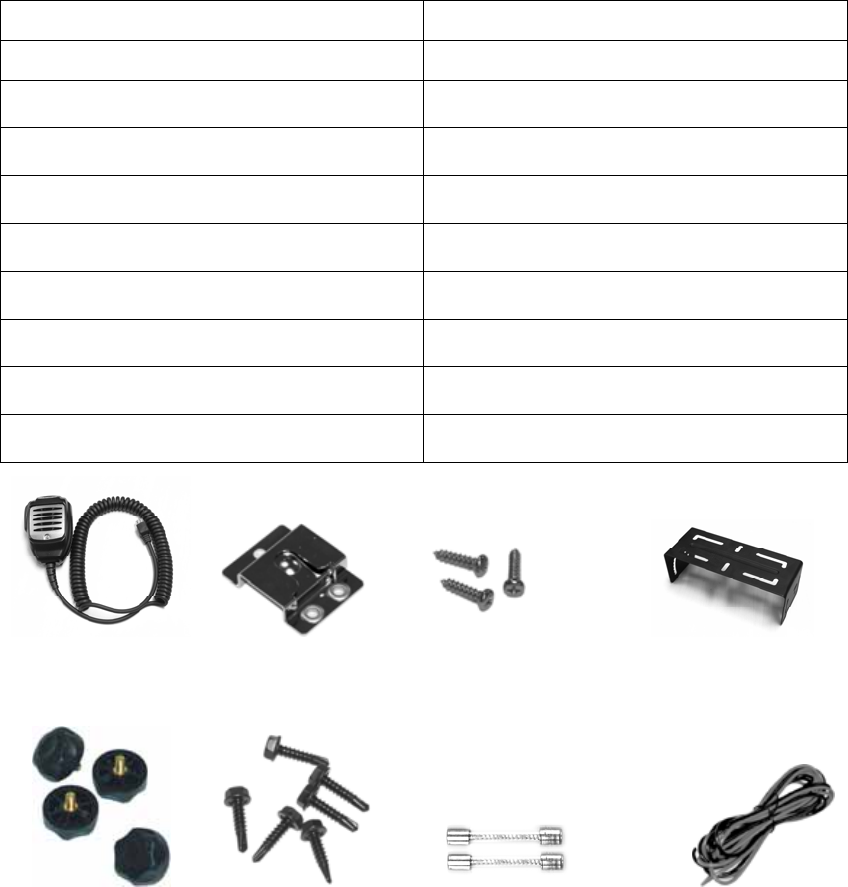
▇ Supplied Accessories
Item Quantity (pcs)
DC Power Cable 1
Mounting Bracket 1
Remote speaker microphone 1
Microphone hanger 1
Microphone hanger screw 3
Adjust knobs 4
Bracket mounting screw set 6
Fuse 2
Owner’s Manual 1
Remote Speaker Microphone Hanger Microphone Mounting bracket
Microphone (SM11R1) Hanger Screw
Adjust knobs Mounting screw set Fuse Power cable
第 10 页 共 31 页
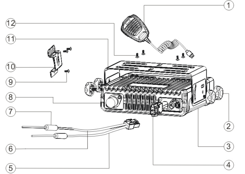
Radio Installation
■ Installing the Radio
1、 Attach the mounting bracket, using the 4.8 x 20mm self-tapping screws, in a location
where convenient operation is accessible.
2、 Connect the antenna and the supplied power cable to the radio.
3、 Slide the radio into the mounting bracket and secure it using the Adjustment knobs.
4、 Mount the microphone hanger, using the 4 x 16mm self-tapping screws, in a location
where it will be within easy reach of the user.
5、 Connect the microphone plug to the microphone jack on the front panel of the radio,
then place the microphone on the hanger.
1. Remote speaker microphone
2. Adjust knob
3. Main unit
4. Power inlet
5. Black lead
6. Red lead
7. Fuse
8. Antenna pedestal
9. 4 ×16mm self-tapping screw
10. Remote speaker microphone hanger
11. Mounting bracket
12. 4.8 × 20mm self-tapping screw
第 11 页 共 31 页
▇ Installation Tools
1. Electric drill: ¢6mm or above
2. Cross head screwdriver
3. Hex socket (used to fix 4.8 × 20mm self-tapping screws)
▇ Warnings:
* The radio operates in 13.6 ± 15%V negative ground systems only. Check the voltage
and polarity of the power supply on the vehicle before installation.
* Be sure to check how far the screw will extend below the radio surface to avoid damage
to the auto wiring or auto parts when drilling mounting holes.
* Connect the radio with the supplied antenna and power cable before installing the radio
by the mounting bracket.
* Install the radio securely using the supplied mounting bracket to make sure that the
radio will not loosen in the event of accidents. The loose radio may cause injury to the
passenger.
* Arrange the installation location of the radio to make sure that the control unit in the front
panel is convenient for operation.
* Be sure to determine the location of the installing holes before installation and drilling.
* Be sure to make room at the rear side of the radio for power cable connection.
* When replacing the fuse in the DC power cable, be sure to replace it with a fuse of the
same specifications. Never replace a fuse with one that has a higher capacity value.
第 12 页 共 31 页
Radio Overview
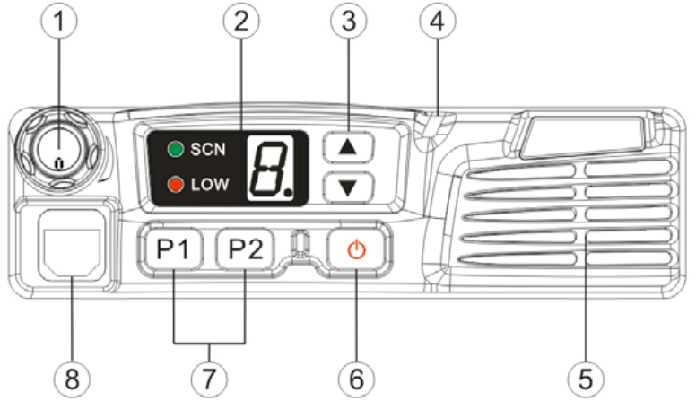
■ Front Panel View
① Volume Knob
Turn the knob clockwise to adjust upwards and counterclockwise to adjust
downwards.
② LED Indicator & 8-segment Numeric Display
Please refer to the “LED status indicator and 8-segment numeric display” section.
③ Programmable Function Key (▲/▼)
Your dealer can program these keys as shortcuts to various radio features.
Please refer to “Programmable Function Key” section.
④ LED Tx-Rx Indicator
⑤ Speaker
⑥ Power Switch
⑦ Programmable Function Key (P1/P2)
Your dealer can program these keys as shortcuts to various radio features.
Please refer to “Programmable Function Key” section.
⑧ Microphone Jack
Insert the microphone plug into this jack.
第 13 页 共 31 页
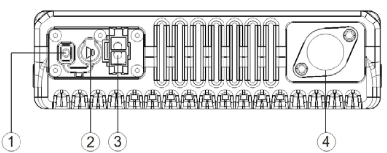
▇ Rear Panel View
① 15PIN (external expansion)
② External Speaker Jack
Used to connect external speaker, for the 3.5mm plug
③ Power inlet
Use HYT supplied DC power cable to access 13.6V DC power.
④ Antenna Pedestal
Used to connect external antenna.
第 14 页 共 31 页
▇ LED Indicators
Name Display Radio Status
Red Transmit a signal
Green Receive a signal
Tx-Rx indicator
Orange flash Receives encode squelch, selcall, 2-Tone/DTMF
signalling call
SCN indicator Green Scan
LOW indicator Red Lit up for low power, goes out for high power
▇ 8-Segment Numeric LED
Figure 1 8-segment Numeric LED
▇ Programmable Function Keys
P1/P2, ▲/ ▼ is programmable for the following functions:
1. Off
2. Channel Up
3. Channel Down
4. Monitor A
5. Monitor B
6. Monitor C
7. Monitor D
8. User Selectable Tone
9. 2-Tone encode Select
10. Tx Power Select
11. Scan
12. Add/Del
13. Reverse Frequency
14. Talk Around
15. Selects squelch level
第 15 页 共 31 页
16. Home channel
17. Public address
18. Scrambler
19. Compander
20. Emergency Call
第 16 页 共 31 页
Basic Operations
Radio Power On/Off
Press the power switch to turn on the radio.
Press and hold down the power switch for about 1 second to turn off the radio.
Adjust the Volume
Turn the Volume Control Knob clockwise to increase the volume, or counter-clockwise to
decrease the volume.
Note:
1. If the radio is programmed with CTCSS/CDCSS, 2-Tone signalling squelch, no
noise will be heard from the speaker even though at maximum volume level.
2. Holding down the Monitor key (Monitor C/D) simultaneously while adjusting
volume level, to hear the current volume level from the speaker.
Monitor
If the Monitor function is set by your dealer, press the Monitor key (programmable) while in
receive mode, to monitor activities on the current channel.
The Monitor key is programmable with one of the following four operating modes by your
dealer:
1、Monitor Unmute-Momentary
Hold down the [MONI] key to open CTCSS/CDCSS/2-Tone signalling squelch.
Release to close the signalling squelch.
2、Monitor Unmute-Toggle
Press the [MONI] key to open CTCSS/CDCSS/2-Tone signalling squelch. Press
again to close the signalling squelch.
3、Carrier Squelch-Momentary
Hold down the [MONI] key to open carrier squelch; Release to close the carrier
squelch.
4、Carrier Squelch-Toggle
Press the [MONI] key to open carrier squelch. Press again to close the carrier
squelch.
Select a Channel
The ▲/▼ or P1-P2 function keys are programmable by your dealer to select a channel.
第 17 页 共 31 页
The Rx/Tx frequency on each channel is set by your dealer.
Press the [Channel Up] key (programmable) to select a higher numbered channel; press
the [Channel Down] key to select a lower numbered channel.
Receive
If CTCSS/CDCSS, 2-Tone has been programmed on the current channel by your dealer,
you can receive calls with matched tones or codes only. If CTCSS/CDCSS, 2-Tone is not
set, you can hear from all the users on the same channel.
Transmit
1. Hold down the [PTT].
2. Dial DTMF number via microphone keypad. (This operation may be unnecessary).
3. Speak into the microphone. The LED is red while calling.
4. Release the [PTT] to return to the receive mode.
5. When transmission ends, put the microphone on hook.
Programmable Power Output
If the current channel is programmed with high power by your dealer, the power output
toggles between high and low upon each press the Tx Power Select key (programmable).
Low power is for battery saving and avoiding interference with other users, low power is
recommended when communication within limited range.
Note:
If the current channel is programmed with low power, press the Tx Power Select key,
an error alert tone is heard while the power output will not change.
If you switch to low power on a channel that was set with high power, this
configuration is done on all other channels that were set with high power.
BOT ID and EOT ID
Your dealer may configure whether to transmit Connect ID (BOT ID) and Disconnect ID
(EOT ID), when connecting or disconnecting a repeater or telephone system. The
following modes are programmable:
1、BOT ID occurs on each press of [PTT].
EOT ID occurs on each release of [PTT].
2、Press the [*] while holding down the [PTT], then BOT ID is transmitted.
Pres the [#] while holding down the [PTT], then EOT ID is transmitted.
第 18 页 共 31 页
Scan
Radio scans all the channels that have been added into the scan list of the current zone.
▇ Scan Start
① Add one or several non-priority channels into the scan list.
② Press the Channel Scan key (programmable) to initiate scan from the current channel,
then scanning proceeds in ascending order by channel number, while the scan LED lit up.
▇ Scan Cease
Scanning pauses or ceases upon the following:
1. Upon repress the Channel Scan key (programmable), scanning ceases, scan LED
goes out, then radio exit the scan mode.
2. Activate the Monitor function.
3. Carrier is detected on a channel that is not set with signalling.
4. Carrier is detected and match signalling is received on a channel that is set with
signalling.
▇ Scan Resume
If scanning pauses on an active channel, the scanning will resume according to the scan
resume mode. The scan resume mode is programmable by your dealer for Carrier
operated scan or Time operated scan.
1. Time operated scan
Scanning remains on an active channel for a programmed time period (programmable
by your dealer), once the timer expires, the radio will begin scanning other channels
even if the active channel is still busy.
2. Carrier operated scan
If carrier is detected during the scan sequence, scanning will remain on the active
channel until there is no activity.
▇ Dual Priority Scan
If dual priority channels are programmed by your dealer, the radio still checks the dual
priority channels for activity at configured intervals, while scanning pauses on a
non-priority channel. When any activity is detected on a priority channel, the radio will
immediately switch to the active priority channel.
▇ Nuisance Channel Temporary Delete
第 19 页 共 31 页
Temporarily delete the selected channel from the scan list during scanning.
When scan pauses on an unwanted channel due to noise, press the Add/Del Scan key
(programmable) to temporarily delete the channel from the scan list. Then scan is
reactivated immediately.
Note: the temporary delete is not memorized once radio exits from the scan mode.
▇ Revert Channel
Upon pressing the [PTT] during scanning, the radio will pause scanning and switch to the
Revert Channel to transmit. This feature is programmable by your dealer.
▇ Off-Hook Scan
If the Off-Hook Scan feature is programmed by your dealer, radio scans no matter the
microphone is in the off or on hook condition. Otherwise, microphone must be on hook for
scanning.
Busy Channel Lockout (BCL)
The feature can be enabled/disabled by your dealer, this feature is to prevent transmission
on a channel that is already in use. Press the [PTT] on a channel that is already in use,
transmission is inhibited and an alert tone is heard. Upon release the [PTT], the alert tone
ceases and radio returns to receive mode. Press the [PTT] to transmit while the channel is
free.
BCL Override
If the BCL Override feature is enabled, you can override the BCL feature to transmit on a
busy channel. Press the [PTT], a BCL alarm will be heard, then repress the [PTT] within
0.5s to override the BCL feature and transmit on the busy channel.
DTMF Call
▇ Manual Dial
Press any key from the DTMF keypad of the microphone, while holding down the [PTT], to
transmit the DTMF frequency, and the DTMF tone will be heard from the local speaker.
Release the [PTT] to remain transmission for 2s (programmable by your dealer), press a
numeric key within the 2s to continue transmission.
▇ Keypad Auto PTT
This feature is programmable by your dealer. If the feature is enabled, press numeric key
to transmit DTMF frequency without pressing the [PTT].
第 20 页 共 31 页
▇ DTMF Speed
6, 8, 10 or 15 digits per second is programmable by your dealer. The feature is designed
to reduce false decoder operation by providing a fixed time period between digits.
▇ Auto Dial
1. Press the [*] on the Mic keypad.
2. Enter the pre-stored DTMF code location number (1~9).
3. LED displays the location number (1.~9.).
4. Press the [PTT] to transmit the stored number.
▇ Redial
1. Press the [*] on the mic keypad.
2. Then press the [0].
3. LED displays 0.
4. Press the [PTT] to transmit the last dialed number (max. 16 digits).
Note: the redial memory is cleared once the radio is turned off.
Code Squelch
This feature can be enabled/disabled via programming by your dealer. If the feature is
enabled, the preset 2-Tone controls radio mute/unmute. The radio will not unmute until
matched signalling is received.
▇ Receive
1. Radio is unmuted when matched 2-Tone signalling (programmed by your dealer) is
received, the user can hear from the transmitter without any other operation.
2. LED flashes orange.
3. Radio is muted upon press the Monitor key (programmable), or no signal is received
within the preset time period.
4. If the Alert Tone is enabled, radio will emit alert when matched signalling is received. If
the Transpond is enabled, radio will transpond a signal to the calling radio. However, radio
will no transpond if a group call is received.
▇ Transmit
1. Holding down the [PTT].
2. Enter the preset DTMF encode (radio encode or group encode) via keypad.
The further operations are the same as that of normal mobile radios.
Red LED lit up while in transmission.
第 21 页 共 31 页
Please refer to the [TTS] key for 2-Tone transmission.
3. Upon release the [PTT], the signalling squelch is disabled and LED flashes orange.
Green LED lit up when signal is received.
4. If the Monitor key (programmable) is pressed, or no signal is received within the
preset time period, the signalling squelch is enabled.
Auto Transpond
The Auto Transpond feature can be programmed by your dealer to operate with Code
Squelch. If the Auto Transpond feature is enabled, radio will automatically transpond a
signal when a call with matched signalling is received. Your dealer may program one type
of call response from the following:
1. Alert
2. Transpond
3. Alert & Transpond
Press any key to stop transpond.
Off Hook Decode
If the feature is enabled by your dealer, CTCSS/CDCSS decode signalling is active no
matter the microphone is in the off/on hook condition. If the feature is disabled,
CTCSS/CDCSS decode signalling is disabled while the microphone is in the off hook
condition.
Time-out Timer (TOT)
▇ Time-out Timer(TOT)
The TOT feature is to prevent user from transmitting on the channel for extended period of
time. This also protects the radio from damage caused by long time transmission.
Once a continuous transmission exceeds the preset time (15~1200s programmable), the
transmission is automatically terminated and alert tone is heard. The alert tone ceases
upon release the [PTT].
The TOT default is 180s, it meets normal operation needs. Any change should be
permitted by professional technicians.
▇ TOT Pre-alert
The radio has a TOT Pre-alert timer. The radio will emit the Pre-alert tone at the
programmed time (1~10s before the TOT timer expires).
第 22 页 共 31 页
▇ TOT Re-key Time
The radio has a TOT Re-key timer. Since transmission is terminated upon the TOT timer
expires, transmission is inhibited if press the [PTT] before the expiration of TOT Re-key
timer (programmable by your dealer as Off, 1~60s).
▇ TOT Reset Time
Upon the press of [PTT], “TOT” begins timing. After the release of [PTT], “TOT” reset timer
begins timing, However, the TOT timer will not reset until the TOT Reset timer expires.
The TOT Reset Time is programmable by your dealer as Off, 1~15s.
Emergency Call
Holding down the Emergency Call key (programmable as long or short press), the radio
will enter the Emergency Call mode and switch to the preset Emergency Channel. The
radio will firstly transmit within the preset time period, and then receive within the preset
time period, and so does the cycle.
The radio will back to the channel before the Emergency Call mode, upon re-holding down
the Emergency Call key (programmable as long or short press).
第 23 页 共 31 页
Programmable Auxiliary Functions
The [P1]-[P2], ▲/▼ are respectively programmable with one of the following auxiliary
functions by your dealer.
Reverse Frequency
If communications between radios are disrupted because of a long distance from the
repeater, the Reverse Frequency function can be used to re-establish communications
with another radio. When the function is activated, the transmit frequency and receive
frequency will be reversed. The preset CTCSS/CDCSS encoding and decoding signals
will also be reversed.
Press the Reverse Frequency key (programmable) to toggle the Reverse Frequency
function ON or OFF.
Talk Around
If the Talk Around feature is enabled, the Rx frequency is used in place of the Tx
frequency when transmitting, and the CTCSS/CDCSS decoding signal is used in place of
the encoding signal when encoding.
Press the Talk Around key (programmable) to toggle the Talk Around function ON or OFF.
Selectable Squelch Level (SQL)
1、 Upon press the SQL key (programmable), LED displays the current squelch level.
2、 Select the desired squelch level via the programmable key ▲/ ▼.
3、 Upon press the [P1] or [P2] key (programmable), LED resets to the original display
mode.
Note: High squelch level may cause the radio to ignore weak signals; while low squelch
level may cause noise or unwanted signals to be heard.
User Selectable CTCSS/DCS(UST)
If the UST feature is enabled by your dealer, the user can temporarily change the
CTCSS/CDCSS codes that preset on the channel.
1. Select a desired channel.
2. Press the [UST] key (programmable) to enter the UST mode.
3. Use the ▲/ ▼ key to select a desired UST code (the newly selected CTCSS/CDCSS
code is valid in the UST mode only), then the CTCSS/CDCSS code on the current
channel is set as the selected UST code.
第 24 页 共 31 页
4. Repress the [UST] key to exit the UST mode, then LED resets to the original display
mode.
Public Address (PA)
The PA feature amplifies audio inputted from the microphone, and the audio can be heard
from the external speaker which is connected via 15PIN expansion port.
1. Press PA key (programmable) to activate the PA feature, then the LED displays “P”.
Repress the PA key to disable the PA feature, then the radio returns to normal user
mode.
2. Once the PA feature is activated, the radio is unable to transmit and receive.
3. Speak into the microphone while holding down the [PTT], your voice can be heard
from the external speaker that is connected to the radio.
While in PA mode or the PA process initiates, the user can adjust volume via the
volume control knob.
4. Release the [PTT] to end PA process, then the radio returns to the PA mode.
Note:
In PA mode, adjust volume via the volume control knob.
While using the PA system, the optional PA accessories and external speaker
must be installed by your dealer.
Dual Home Channel
Upon press the Home Channel key (programmable), the radio will promptly go to the
programmed home channel.
When dual home channels are set, press the programmed Home Channel key to promptly
go to Home Channel 1, press again to promptly go to Home Channel 2, and press for the
third time to return to the original channel.
2-Tone Encode Select
1. Press the 2-Tone Encode Select key (programmable), local LED displays the preset
2-Tone encode sequence (0~9).
2. Press the ▲/ ▼ key to select 2-Tone encode (0~9).
3. Holding down the [PTT] to transmit the selected 2-Tone encode.
4. Upon release the [PTT], the signalling squelch is disabled and LED flashes orange.
5. If the Monitor key is pressed, or no signal is received within the preset time period, the
signalling squelch is enabled.
第 25 页 共 31 页
Note: If no signal is received within the preset time period, the signalling squelch is
enabled.
Compander
Press the Compander key (programmable) to toggle the compander feature ON or OFF.
Scrambler
Press the Scrambler key (programmable) to toggle the Scrambler feature ON or OFF.
Note: The emphasis/de-emphasis feature is disabled while the Scrambler is ON, and
enabled while the Scrambler is OFF.

第 26 页 共 31 页
Key Assignment
Programmable function keys [P1]-[P2], ▲/▼.
Key Assignment
No Function keys Setting Display Remarks
1 [P1] Off
1
CH Number No function
CH Up
2
CH Number Channel Up
CH Down
3
CH Number Channel Down
MONI A
4
CH Number MONI A: Carrier Squelch-momentary
MONI B
5
CH Number MONI B: Carrier Squelch-toggle
MONI C (default)
6
CH Number MONI C: Squelch off-momentary
MONI D
7
CH Number MONI D: Squelch off -toggle
User Selectable Tone
8
UST Number (0.-9.) CTCSS/DCS Tone
Sel 2Tone
9
2Tone Number (0.-9.) Select 2-Tone encode
TX power Select
10
CH Number Switch transmit power
Scan
11
● Scan
Add/Del
12
● Temporarily delete nuisance channel
Reverse Freq
13
CH Number Reverse frequency
Talk Around
14
CH Number Talk Around
SEL SQL
15
SQL Number (0.-9.) Select squelch level
Home CH
16
HomeCH Number(1-8)Home Channel
Public Address
17
P Public address

第 27 页 共 31 页
Scrambler
18
CH Number Scrambler
Compander
19
CH Number Compander
Emergency Call
20
EmergencyCH Number (1- 8)Emergency call
2 [P2] Off
1
CH Number No function
CH Up
2
CH Number Channel Up
CH Down
3
CH Number Channel Down
MONI A
4
CH Number MONI A: Carrier Squelch-momentary
MONI B
5
CH Number MONI B: Carrier Squelch-toggle
MONI C
6
CH Number MONI C: Squelch off-momentary
MONI D
7
CH Number MONI D: Squelch off -toggle
User Selectable Tone
8
UST Number (0.-9.) CTCSS/DCS Tone
Sel 2Tone
9
2Tone Number (0.-9.) Select 2-tone encode
TX Power Select
10
CH Number Switch transmit power
Scan (default)
11
● Scan
Add/Del
12
● Temporarily delete nuisance channel
Reverse Freq
13
CH Number Reverse frequency
Talk Around
14
CH Number Talk around
SEL SQL
15
SQL Number (0.-9.) Select squelch level
Home CH
16
HomeCH Number (1- 8) Home channel
Public Address
17
P Public address
Scrambler
18
CH Number Scrambler

第 28 页 共 31 页
Compander
19
CH Number Compander
E
mergency Call
20
EmergencyCH Number (1- 8)Emergency call
3 ▲ ( [UP] ) Off
1
CH Number No function
CH Up (default)
2
CH Number Channel Up
CH Down
3
CH Number Channel Down
MONI A
4
CH Number MONI A: Carrier Squelch-momentary
MONI B
5
CH Number MONI B: Carrier Squelch-toggle
MONI C
6
CH Number MONI C: Squelch off-momentary
MONI D
7
CH Number MONI D: Squelch off -toggle
User Selective Tone
8
UST Number(0.-9.) CTCSS/DCS Tone
Sel 2Tone
9
2Tone Number(0.-9.) Select 2-Tone encode
TX Power Select
10
CH Number Switch transmission power
Scan
11
● Scan
Add/Delete
12
● Temporarily delete nuisance channel
Reverse Freq
13
CH Number Reverse Frequency
Talk Around
14
CH Number Talk around
SEL SQL
15
SQL Number(0.-9.) Select squelch level
Home CH
16
HomeCH Number (1-8) Home channel
Public Address
17
P Public address
Scrambler
18
CH Number Scrambler
Compander
19
CH Number Compander

第 29 页 共 31 页
Emergency Call
20
EmergencyCH Number (1- 8)Emergency Cal
4 ▼( [DOWN] ) Off
1
CH Number No function
CH Up
2
CH Number Channel Up
CH Down (default)
3
CH Number Channel Down
MONI A
4
CH Number MONI A: Carrier Squelch-momentary
MONI B
5
CH Number MONI B: Carrier Squelch-toggle
MONI C
6
CH Number MONI C: Squelch off-momentary
MONI D
7
CH Number MONI D: Squelch off -toggle
User Selective
Tone
8
UST Number(0.-9.) CTCSS/DCS Tone
Sel 2Tone
9
2Tone Number(0.-9.) Select 2-Tone encode
TX Power Select
10
CH Number Switch transmission power
Scan
11
● Scan
Add/Delete
12
● Temporarily delete nuisance channel
Reverse Freq
13
CH Number Reverse Frequency
Talk Around
14
CH Number Talk around
SEL SQL
15
SQL Number(0.-9.) Select squelch level
Home CH
16
HomeCH Number(1-8) Home channel
Public Address
17
P Public address
Scrambler
18
CH Number Scrambler
Compander
19
CH Number Compander
mergency Call
20
EmergencyCH Number (1- 8)Emergency Call

第 30 页 共 31 页
5 Selector Knob Volume Knob CH Number Volume Knob
Note: the above “CH Number” can be any value among “1 – 8”.
第 31 页 共 31 页
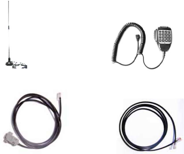
Optional accessories
Antenna Remote Speaker Microphone with Keypad (SM07R1)
Programming Cable (PC06) Clone Cable (CP06)
HYT endeavors to achieve the accuracy and completeness of this manual, but cannot
guarantee its accuracy at all time. All the above specifications and design are subject to
change by HYT without notice.
All the reproduction and translation of this manual without authorization of HYT is not
allowed.