HYT Science and Technology Co TM-800V Two Way Radio User Manual TM800 p65
Shenzhen HYT Science &Technology; Co Ltd Two Way Radio TM800 p65
UserManual.wiki
>
HYT Science and Technology Co
>
TM 800V User Manual
Users Manual
Navigation menu
Upload a User Manual
Namespaces
Wiki Guide
HTML
PDF
Info
Views
User Manual
Discussion / Help
Navigation
![LCD DisplayIndicator Description1. Display zone / channel number.2. Display zone / channel label (setby your dealer, up to 12 alphanumeric characters).3. Display channel Frequency4. Display the preprogrammed func-tions1. Display zone / channel number.2. Display transmit power level(H, M or L).3. Display the preprogrammed func-tionsRadio OverviewAppears when the selected channel isbusy.Appears when [MONI] key is pressedto disable CTCSS, CDCSS, DTMF or2-Tone/5-Tone.Appears when [MONI] key is pressedto switch the speaker on.1. Indicate second development feature.2. Appears when the auxiliary functionis activated. SCAN Appears while scanning.Appears when transmitting a selectivecall.Appears when a new message isreceived.Appears when the selected zone is inthe scan list.Appears when the selected channel isin the scan list.11ACALLTM800.p65 2005-6-29, 10:1612](https://usermanual.wiki/HYT-Science-and-Technology-Co/TM-800V/User-Guide-558747-Page-12.png)
![Turn the Radio On/OffPress the Power switch to switch the radio on.Press and hold the Power switch for approximately 1 sec-ond to switch the radio off.If Power on Password is set to protect your radio, “Chk P”and the cursor will appear on the display when power isturned on. You can unlock the radio by entering the correctpassword (8 digits maximum):1. Select a digit (0-9) by rotating the selector knob.If you are using an optional microphone with a keypad,you can also enter the password by pressing the ap-propriate keypad keys.2. Press the [PF3] / [PF4] key to move cursor forward andbackward.This step can be skipped when using the keypad.3. Repeat steps 1 and 2 to enter the entire password.4. Press the [PF6] key or the [PTT] key to complete theentry.Basic OperationsAdjust the VolumeSelector Knob, [¡ø] / [¨‹] or the function keys PF1-PF6 canbe programmed with VOL Up / VOL Down features toadjust volume level.Rotate the Selector Knob clockwise or press the key whichbe programmed as [VOL Up] key to increase the volume;rotate the knob counter-clockwise or press the key whichbe programmed as [VOL Down] key to decrease thevolume. The current volume level is displayed on the LCD.The LCD returns to original display mode in 5 seconds.Press any key to exit from the volume level display mode.MonitorIf monitor feature is set by your dealer, press the key pro-grammed as [MONI] in receive mode to monitor activity onyour selected channel.Your dealer can select one of the following four modes formonitor feature:14TM800.p65 2005-6-29, 10:1615](https://usermanual.wiki/HYT-Science-and-Technology-Co/TM-800V/User-Guide-558747-Page-15.png)
![Basic OperationszzzzzMonitor Unmute-MomentaryHold down the [MONI] key to open CTCSS/CDCSS/DTMF/2-Tone/5-Tone signalling squelch. Release to close thesignalling squelch.zzzzzMonitor Unmute-TogglePress the [MONI] key to open CTCSS/CDCSS/DTMF/2-Tone/5-Tone signalling squelch. Press again to closethe signalling squelch.zzzzzCarrier Squelch-MomentaryHold down the [MONI] key to open carrier squelch; Re-lease to close the carrier squelch.zzzzzCarrier Squelch-TogglePress the [MONI] key to open carrier squelch. Pressagain to close the carrier squelch.Select a ChannelSelector Knob, [¡ø] / [¨‹] or the function keys PF1-PF6 canbe programmed with CH Up/ CH Down features to select achannel. Transmit/Receive frequencies of the channel areset by your dealer.Rotate the Selector Knob clockwise or press the key whichbe programmed as [CH Up] key to select a channel upwards;Turn the knob counterclockwise or press the key which beprogrammed as [CH Down] key to select downwards.Select a ZoneSelector Knob, [¡ø] / [¨‹] or the function keys PF1-PF6 canbe programmed with Zone Up/ Zone Down features toselect a zone. Transmit/Receive frequencies of the chan-nel are set by your dealer.Rotate the Selector Knob clockwise or press the key whichbe programmed as [Zone Up] key to select a zone upwards;Turn the knob counterclockwise or press the key which beprogrammed as [Zone Down] key to select downwards.ReceiveIf your dealer has programmed CTCSS/CDCSS/DTMF/2-Tone/5-Tone signalling on the selected channel, you willhear calls only when the matching code or tone is received;otherwise, all calls on the same channel can be heard.15TM800.p65 2005-6-29, 10:1616](https://usermanual.wiki/HYT-Science-and-Technology-Co/TM-800V/User-Guide-558747-Page-16.png)
![Transmit1. Press the key programmed as [MONI] to make sure thatthe selected channel is not in use.2. Hold down the [PTT] key.3. Dial a DTMF number using the microphone keypad.Step 3 is not necessary all the time.4. Speak into the microphone with normal voice. The LEDglows red during transmission.5. Release the [PTT] key to receive.6. When your conversation is finished, return the micro-phone to its hanger.Selectable Power LevelIf transmit power (programmed by your dealer) is set to“high” (or “middle”) on any given channel, press the keyprogrammed as [TX Power] to toggle the TX power amonghigh, middle and low. The current power level is indicatedby “H” /”M” / “L” icon on the LCD.Since low power helps to conserve battery power andreduce the risk of interfering with others, you are recom-mended to select low power when communication qualityis guaranteed.Basic OperationsNotes:zzzzzPress the [TX Power] key while using a channel pro-grammed with low power, an error tone will sound andthe transmit power will not change.zzzzzWhen changing a channel from high/middle power tolow power, all other channels programmed with high/middle power will change to low power accordingly.Beginning/End of Transmission ID SignalThe radio can be programmed to send Beginning/End ofTransmission ID when accessing / releasing repeaters ortelephone systems. The ID signal includes DTMF and5-Tone types. Two modes can be configured:zzzzzPress the [PTT] key to send a Beginning of Transmis-sion ID Signal; Release the [PTT] key to send an End ofTransmission ID Signal.zzzzzPress [*] while holding down the [PTT] key to send aBeginning of Transmission ID Signal; press [#] whileholding down the [PTT] key to send an End of Transmis-sion ID Signal (for DTMF type only).16TM800.p65 2005-6-29, 10:1617](https://usermanual.wiki/HYT-Science-and-Technology-Co/TM-800V/User-Guide-558747-Page-17.png)
![Channel Scan¡ö¡ö¡ö¡ö¡öScan TypeszzzzzSingle Zone ScanAll channels in the current zone that have been addedto the scan list can be scanned.zzzzzMulti Zone ScanAll channels within all the zones that have been addedto the scan list can be scanned.zzzzz List Zone ScanThe radio only scans the channels within the specifiedrange of zones that have been added to the scan list.Individually each zone is assigned with a scan list, whichprovides quick recognition of the zones to be locked outof scan list.Note: Scan list for each zone can be added/ deleted.¡ö¡ö¡ö¡ö¡ö Scan StartPress the key programmed as [SCN], scan starts from thecurrent channel and ascends through the channel num-bers in scan list. “SCAN” appears on the LCDBasic Operations(“-SCAN X - ” in List zone scan mode, “X” is the current listnumber).Note: Scan function can be used only when two or morechannels are in the scan list.¡ö¡ö¡ö¡ö¡ö Scan Stop1. Press the [SCN] key again to stop scanning. “SCAN”disappears on the LCD.2. Activate the Monitor function.3. Carrier is detected on channels where no signalling isset.4. Carrier is detected on channels where signalling is set,and the matching signalling is received.¡ö¡ö¡ö¡ö¡ö Scan RestartWhen the radio stops on a busy channel, scanning can berestarted according to the restart mode, which can beprogrammed by the dealer as carrier-operated scan ortime-operated scan.17TM800.p65 2005-6-29, 10:1618](https://usermanual.wiki/HYT-Science-and-Technology-Co/TM-800V/User-Guide-558747-Page-18.png)
![zzzzzCarrier Operated ScanScanning remains on an active channel until there areno activities; while the channel is free, the radio re-mains on the channel for the programmed Dropout De-lay Time (programmed by your dealer) before it resumesscanning.zzzzzTime Operated ScanScanning remains on the active channel for only theprogrammed Dropout Delay Time (programmed by yourdealer) before it resumes scanning. After the expirationof Dropout Delay Time, the radio will begin scanningother channels even if the channel is still busy.¡ö¡ö¡ö¡ö¡ö Dual Priority ScanIf your dealer has programmed dual priority channels, theradio will periodically detect the activity on priority chan-nels while stopping on non-priority channels. When anyactivity is detected on the priority channels, the radio willswitch to the priority channels for communications.“P1” appears on the LCD when the channel is set asPriority 1, “P2” appears when set as Priority2, and “PP”when set as both Priority 1 and Priority 2.Basic Operations¡ö¡ö¡ö¡ö¡ö Operator Selectable Priority ChannelIf priority channel is programmed by your dealer as “Op-erator Selectable”, you can set the current channel aspriority or non-priority channel:Press the key programmed as [MONI] twice while holdingdown the key programmed as [SCN], the current channel ischanged to “Priority 2”.Press the [MONI] key three times while holding down the[SCN] key, the current channel is changed to “Priority 1”.Press the [MONI] key four times while holding down the[SCN] key, the current channel restores to original setting.¡ö¡ö¡ö¡ö¡ö Scan Add/DeleteThis feature allows you to add/delete a channel to/from thescan list in the non-scan mode.1. Select the channels to be added/ deleted by using thechannel selector knob.2. Press the key programmed as [Add/Del] to toggle be-tween ADD and DELETE. “ ”appears on the LCDwhen a channel is added.Note: The radio only scans the channels that have beenadded to the scan list.18TM800.p65 2005-6-29, 10:1619](https://usermanual.wiki/HYT-Science-and-Technology-Co/TM-800V/User-Guide-558747-Page-19.png)
![¡ö¡ö¡ö¡ö¡ö Look Back Temporary DisableWhen scanning looks back and stops on a priority channel,press the key programmed as [Add/Del] to deactivate theLook Back function.¡ö¡ö¡ö¡ö¡ö Nuisance Channel Temporary DeleteThis feature allows you to temporarily add/delete a chan-nel to/from the scan list during scanning.When scanning stops on an undesired channel (e.g. nui-sance channel), press the key programmed as [Add/Del],the channel is temporarily removed from the scan list andscanning resumes.Note: The addition/ deletion of channels are not savedwhen radio exits from the scan mode.¡ö¡ö¡ö¡ö¡ö Revert ChannelPress the [PTT] key during scanning, the radio will stopscanning and switch to the preset revert channel(programmed by your dealer) for transmission.Basic Operations¡ö¡ö¡ö¡ö¡ö Off Hook ScanNormally scanning is not controlled by microphone hookstatus, it also means that the radio always scans, andstops by signal presence. But if your dealer has programmedOff Hook Scan feature, microphone must be on hook forscanning.Busy Channel Lockout (BCL)When activated by your dealer, the BCL feature will pre-vent you from talking on a channel that is already in use.Press the [PTT] key while the channel is in use, the radiowill emit an alert tone and transmission will be inhibited.Release the [PTT] key to stop the alert tone. Wait until thechannel is not in use before you try to transmit again.BCL OverrideIf BCL Override feature is activated, you can override theBCL feature and transmit on a busy channel. To overridethe BCL, release the [PTT] key when the alert tone sounds,then press the [PTT] key again within 0.5 second.19TM800.p65 2005-6-29, 10:1620](https://usermanual.wiki/HYT-Science-and-Technology-Co/TM-800V/User-Guide-558747-Page-20.png)
![DTMF Call¡ö¡ö¡ö¡ö¡ö Manual DialHold down the [PTT] key, then enter the DTMF number bypressing the keys ([0] ~ [9], [*], [#]) on optional microphonekeypad. Audible tone sounds when corresponding DTMFtone is transmitted.The radio can be programmed by your dealer to remain intransmit mode for 2 seconds after releasing the [PTT] key.Press any numeric key within 2 seconds to continuetransmission.¡ö¡ö¡ö¡ö¡ö Keypad Auto PTTIf this feature is programmed by your dealer, you can trans-mit a DTMF tone by pressing the keys on optional micro-phone keypad without holding down the [PTT] key.¡ö¡ö¡ö¡ö¡ö Store & SendIf this feature is activated, enter a preset DTMF number (16digits maximum) in receive mode, then press the [PTT] keyto place the call. The DTMF number scrolls across the LCDdisplay as it is entered, and its corresponding audible tonesounds.Notes:zzzzzIf you enter a wrong digit or decide not to dial the number,press any key other than the power switch on the frontpanel to exit.zzzzzThe [D] key can be programmed by your dealer as a nulltone. This also means that “D” tone is not transmittedwhen “D” is entered. Instead, “D” is used for a pausetime (programmable by your dealer).¡ö¡ö¡ö¡ö¡ö Dial SpeedYour dealer can select dial speed at 6, 8, 10 or 15 digits persecond.This is designed to reduce false decoder operation by pro-viding a fixed time period between digits. Default: 10 digitsper second¡ö¡ö¡ö¡ö¡ö Store DTMF NumbersYou can store DTMF numbers (16 digits maximum) in eachof the 32 Auto Dial memory locations (01¡«32).1. Press the [#] key, “D— — — — ” appears on the LCD.2. Enter the DTMF number (16 digits maximum).Basic Operations20TM800.p65 2005-6-29, 10:1621](https://usermanual.wiki/HYT-Science-and-Technology-Co/TM-800V/User-Guide-558747-Page-21.png)
![You can enter the digits 0-9, A-F.To enter A,B,C,D,E,F, hold down the [PTT] key, thenenter 2, 5, 8, 0, *, # respectively.3. Press the [#] key, “— — —” appears on the LCDindicating the memory location.4. Enter the desired memory location number (01¡«32).5. Press the [#] key again to store the DTMF number intothe memory location.If you enter a wrong digit or decide not to dial the number,press any key other than the power switch on the frontpanel to exit.¡ö¡ö¡ö¡ö¡ö Confirm Stored DTMF Numbers1. Press the [*] key, “A— — ” appears on the LCD.2. Enter the desired memory location number (01¡«32).The stored DTMF number or caller ID is displayed on theLCD. Press any key other than the [PTT] key, the originaldisplay is restored.¡ö¡ö¡ö¡ö¡ö Dial Stored DTMF Numbers1. Press the [*] key, “A— — ” appears on the LCD.Basic Operations2. Enter the desired memory location number (01¡«32).The stored DTMF number or caller ID is displayed on theLCD.3. Press the [PTT] key to place the call.¡ö¡ö¡ö¡ö¡ö Clear Stored DTMF Numbers1. Press the [#] key, “D— — — — —” appears on the LCD.2. Press the [#] key again, “D Clear” appears on the LCD.3. Enter the desired memory location number (01¡«32).To cancel the process, press any key other than[0]¡«[9].4. Press the [#] key, the stored DTMF number is cleared.¡ö¡ö¡ö¡ö¡ö Redial1. Press the [*] key, “A— — ” appears on the LCD.2. Press the [0] key twice, the last number (16 digitsmaximum) you dialed is redialed.The redialed number is displayed on the LCD.3. Press the [PTT] key to place the call.Note: The redial memory is cleared when the radio is turnedoff.21TM800.p65 2005-6-29, 10:1622](https://usermanual.wiki/HYT-Science-and-Technology-Co/TM-800V/User-Guide-558747-Page-22.png)
![Code SquelchThe code squelch feature can be programmed by yourdealer.If this feature is activated, squelch turns on only when thereceived DTMF/2-Tone/5-Tone code matches the radio IDcode (set by your dealer). Otherwise, your radio will notrespond to the calls.¡ö¡ö¡ö¡ö¡ö Receive1. When the received DTMF/2-Tone/5-Tone code matchesthe radio ID code (set by your dealer), squelch turns onand you will hear the call without any further actionafter an alert tone/Transpond finishes.2. “CALL” icon appears on the LCD and radio LED flashesorange.3. Signalling squelch will turn back ON when you pressthe key programmed as [MONI] or when no signal isreceived for the preset time period.4. The radio can be programmed to sound an alert tonewhen receiving a matching code.Basic OperationsIf Transpond for Code Squelch function is enabled, theradio will send a transpond signal (programmed by yourdealer) to the calling station when receiving the match-ing code. The Transpond for Code Squelch functioncan not be used in Group Call mode.¡ö¡ö¡ö¡ö¡ö Transmit1. Hold down the [PTT] key.2. Enter the preset DTMF code (ID code of the called radioor group) through the keypad.zzzzzIf desired, you can use “store and send” or “speeddial” function to transmit codes. Then operates themobile radio in the same way as a portable radio.zzzzzDuring code transmission, “CALL” icon appears onthe LCD and radio LED glows red.zzzzzPlease refer to the [TTS], [FTS] key for 2-Tone/5-Tone transmission.3. Release the [PTT] key, signalling squelch will turn OFFand LED flashes orange. Radio LED glows green whena signal is received and flashes orange again when thesignal drops out.22TM800.p65 2005-6-29, 10:1623](https://usermanual.wiki/HYT-Science-and-Technology-Co/TM-800V/User-Guide-558747-Page-23.png)
![4. Signalling squelch will turn back ON when you pressthe key programmed as [MONI] or when no signal isreceived for the preset time period.Auto TranspondThe Auto Transpond function can be programmed by yourdealer to use with the Code Squelch function. Whenactivated, the radio will send a transpond signal whenreceiving the matching code. Four types of transpond sig-nal can be programmed by your dealer:zzzzzRinging tonezzzzzAlert TonezzzzzTranspond codezzzzzAlert Tone + Transpond codePress any key to stop the ringing tone.Off-Hook DecodeIf your dealer has activated the feature, CTCSS/DCS de-code signalling will be activated only when the microphoneis on-hook; otherwise, decode signalling is deactivatedduring the off hook condition, squelch works as carriersquelch.Time-Out-Timer (TOT)Time-out-Timer (TOT) feature can be set in each zone.¡ö¡ö¡ö¡ö¡ö TOTTOT is used to prevent user from transmitting on the samechannel for extended period of time. This also protects theradio from damage caused by long time transmissions.If continuous transmission exceeds the preset time(15-1200 seconds), the transmission will be inhibited andan alert tone will sound. Release the [PTT] key to stop thealert tone.¡ö¡ö¡ö¡ö¡ö TOT Pre-AlertWhen this feature is activated, the radio will sound an alerttone at the programmed pre-alert time before TOT expires.TOT will expire when the selected time passes after a“Pre-Alert Tone”. Pre-alert time (1-10 seconds before theTOT expiration) is set by your dealer.¡ö¡ö¡ö¡ö¡ö TOT Rekey TimeWhen this feature is activated, transmission will remaininhibited until TOT Re-key Time expires, even if you havepressed the [PTT] key. Rekey time (Off, 1-60 seconds ) isset by your dealer.Basic Operations23TM800.p65 2005-6-29, 10:1624](https://usermanual.wiki/HYT-Science-and-Technology-Co/TM-800V/User-Guide-558747-Page-24.png)
![¡ö¡ö¡ö¡ö¡ö TOT Reset TimeTOT won’t reset even after PTT is released unless the TOTReset Timer has expired.Reset time (Off, 1-15 seconds ) is set by your dealer.Emergency CallHold down the key programmed as [Emergency] for longerthan a preset time (“Emergency Key Delay Time”, program-mable by your dealer) to enter emergency call mode.The radio will switch to the preset emergency zone /channel, then transmit and receive for a preset time in turnautomatically.While in Emergency mode, switch the power OFF or holddown the key again for longer than a preset time(“Emergency Key Delay Time”, programmable by yourdealer) to exit Emergency mode .Stun & ReviveThis feature allows user to enable/disable the transmis-sion/reception over the air by transmitting stun code.Basic OperationsStun code (1-16 digits) is programmable. When receivingthe stun code, the radio will enter stun mode. The radio willreturn to normal mode upon receiving a revive code (stuncode + [#]).3 types of stun are shown as following:zzzzzInhibit transmissionzzzzzInhibit both transmission and receptionzzzzzKill (inhibit all radio functions)24TM800.p65 2005-6-29, 10:1625](https://usermanual.wiki/HYT-Science-and-Technology-Co/TM-800V/User-Guide-558747-Page-25.png)
![Your dealer can program the following auxiliary functionsto the programmable keys PF1-PF6.Reverse FrequencyIf communications between radios are disrupted becauseof a long distance from the repeater, reverse frequencyfunction can be used to re-establish communications toanother radio. When the function is activated, the transmitfrequency and receive frequency will be reversed. Thecorresponding CTCSS/DCS encoding and decoding sig-nals will also be reversed.Press the key programmed as [Reverse] to toggle the re-verse frequency function ON and OFF. ON OFFTalkaroundIf Talkaround is programmed, the transmit frequency canbe changed to be the same as the receive frequency. TheProgrammable Auxiliary FunctionsCTCSS/DCS encoding signals also change to be the sameas the decoding signals.Press the key programmed as [TA] to toggle the Talkaroundfunction ON and OFF. ON OFFSelectable Squelch Level1. Press the key programmed as [SEL SQL], the currentsquelch level is displayed on the LCD as shown below.2. Turn the Selector Knob to select your desired squelchlevel.3. Press any key other than the power switch to save theselected squelch level. The LCD returns to the originaldisplay mode.25TM800.p65 2005-6-29, 10:1626](https://usermanual.wiki/HYT-Science-and-Technology-Co/TM-800V/User-Guide-558747-Page-26.png)
![Note: If the squelch level is set too high, you may not effi-ciently receive weak signals; if the level is set too low, youmay hear a constant white noise, a sputtering noise, orunwanted signals.User Selectable Tone (CTCSS/DCS)This function can be programmed by your dealer to tempo-rarily change the preset CTCSS/DCS frequency on achannel.1. Select your desired channel.2. Press the key programmed as [UST] to enter the USTmode.3. Use the Selector Knob to select a desired UST code/name. The selected CTCSS/DCS frequency is valid onlyin UST mode.4. Press the [UST] key again, the radio exits from USTmode and the LCD returns to the original display mode.Public AddressThis function can be used to amplify all the audio from thespeaker and output the audio through external speaker.1. Press the key programmed as [PA] to activate PublicAddress function. “PA” appears on the LCD display.Press the key again to deactivate this function and re-turn to normal user mode.2. In PA mode, no transmission and reception occurs.3. Hold down the [PTT] key and speak into the microphone,your voice can be heard from the external speaker thatis connected to the radio. “PA On” appears on the LCDdisplay.4. Release the [PTT] key, the public address process haltsand “PA” appears on the LCD display.Notes:zzzzzIn Public Address mode, turn the volume knob to adjustthe volume.zzzzzTo use this function, the dealer should install publicaddress optional accessory and external speaker.Programmable Auxiliary Functions26TM800.p65 2005-6-29, 10:1627](https://usermanual.wiki/HYT-Science-and-Technology-Co/TM-800V/User-Guide-558747-Page-27.png)
![Dual Home ChannelsPress the key programmed as [Home CH], the radio will goto the programmed home channel.When dual home channels are set, press the key pro-grammed as [Home CH] to switch to Home Channel 1, pressagain to switch to Home Channel 2, and press for the thirdtime to return to the original channel.Horn Alert1. Press the key programmed as [HA] to activate HornAlert function, “HA” appears on the LCD display.2. The radio’s accessory ports HRI and HRO is connectedwhen receiving calls of the matching 2-Tone/5-Tone/DTMF code from the base station or other radios.3. Press the [HA] key again to exit from the Horn Alertmode.Note:This function is especially helpful when user is away fromthe radio. It can be used to control the electronic devicesover the air.Selectable 2-Tone Encode1. Press the key programmed as [TTS], the programmed2-Tone code or name will be displayed on the LCD.2. Turn the selector knob to select 2-Tone code (01-32) orname.3. Hold down the [PTT] key to transmit the selected code.4. Release the [PTT] key, signalling squelch turns off andradio LED flashes orange.5. Press the key programmed as [MONI], signalling squelchturns back on.Note: The radio will opens signalling squelch automaticallyif no signal is received for the preset period of time.Selectable 5-Tone Encode1. Press the key programmed as [FTS], the programmed5-Tone code or name will be displayed on the LCD.2. Turn the selector knob to select 5-Tone code (01-32) orname.3. Hold down the [PTT] key to transmit the selected code.Programmable Auxiliary Functions27TM800.p65 2005-6-29, 10:1628](https://usermanual.wiki/HYT-Science-and-Technology-Co/TM-800V/User-Guide-558747-Page-28.png)
![4. Release the [PTT] key, signalling squelch turns off andradio LED flashes orange.5. Press the key programmed as [MONI], signalling squelchturns back on.Note: The radio will opens signalling squelch automaticallyif no signal is received for the preset period of time.Display FrequencyPress the key programmed as [DFreq], LCD will display thefrequency of the current channel.Display LabelPress the key programmed as [DLabel], LCD will displaychannel label.Display ModeThe radio will toggle among the 5 display modes each timewhen the key programmed as [DMode] is pressed.5 display modes are shown as follows:Channel numberProgrammable Auxiliary FunctionsChannel labelZone numberZone labelChannel frequencyLCD BacklightPress the key programmed as [LCD Backlight] to toggleLCD backlight on/offCompanderPress the key programmed as [Compander] to toggleCompander on/off.ScramblerPress the key programmed as [Scrambler] to toggle Scram-bler on/off.Note: Emphasis/de-emphasis features are turned off whenscrambler is activated and turned on when scrambler isdeactivated.28TM800.p65 2005-6-29, 10:1629](https://usermanual.wiki/HYT-Science-and-Technology-Co/TM-800V/User-Guide-558747-Page-29.png)
![GPS ReportWhen GPS receiver is installed, press the key programmedas [Send GPS] to transmit your position data.Short Message£¨£¨£¨£¨£¨under development£©£©£©£©£©Status Message£¨£¨£¨£¨£¨under development£©£©£©£©£©Optional Signalling (DTMF/2-Tone/5-Tone)The preset functions are activated when the received sig-nal matches the optional signalling.When optional signalling is programmed on a channel orzone, radio LED will flash orange and the radio will soundan alert tone or transpond to the call if a signal containingthe correct tone/code is received.Programmable Auxiliary Functions29TM800.p65 2005-6-29, 10:1630](https://usermanual.wiki/HYT-Science-and-Technology-Co/TM-800V/User-Guide-558747-Page-30.png)
![No. Menu Item LCD Display1 Function Set Function Set2 Power On Text Power On Text3 Power On Password PWR Password4 UST Code UST Code5 Key Assignment Key AssignPress the [PF6] key to enter the selected menu. In User Set mode, turn the power off and back on to enter the Conventionalmode.In User Set mode, you can operate as following:1. Turn the Selector Knob to make settings;2. Press the [PF6] key to save the settings and enter the next setting item;3. Press [Up]/[Down] to select the setting item upwards/downwards without saving the settings;4. Press the [PF1] key to return to user set menu mode.31Turn the power on while holding down the [PF1] key, the radio enters User Set mode after correct power-on password isentered (if Power-On Password is set). In User Set mode, the following menus can be selected:zzzzzMain MenuUser Set ModeTM800.p65 2005-6-29, 10:1632](https://usermanual.wiki/HYT-Science-and-Technology-Co/TM-800V/User-Guide-558747-Page-32.png)
![¡ö¡ö¡ö¡ö¡ö Function SetSelect “Function Set” in main menu and press the [PF6] key to make settings as following:Function SetNo. Function Setting Display RemarksHome Off Home OffHome 1 On Home 1 OnHome 2 On Home 2 OnHome Both On Home Both OnZone Home Channel Home ZoneZone 1 Selector Knob: change zone or channelChannel Home1 1 [PF5]: Toggle between zone and channelZone 1 Selector Knob: change zone or channelChannel Home2 1 [PF5]: Toggle between zone and channel¡ö¡ö¡ö¡ö¡ö Power On TextSelect “Power on Text” in main menu and press the [PF6] key to make settings. The power-on text will be displayed. Press the[PF1] key to enter Text Edit mode. Please refer to Appendix 1 “Entering Characters” for more details.Power On TextFunction Setting Display RemarksBlank — — — — — — — Please refer to Appendix 1 “Character Input”.Text Welcome 12 characters maximum.12Home ChannelHome Channel 1Home Channel 2Power On Text32User Set ModeTM800.p65 2005-6-29, 10:1633](https://usermanual.wiki/HYT-Science-and-Technology-Co/TM-800V/User-Guide-558747-Page-33.png)
![¡ö¡ö¡ö¡ö¡ö Power On PasswordSelect “PWR Password” in the main menu and press the [PF6] key to make settings. “Power On Password” will be displayed.Press the [PF1] key to enter Password Edit mode. Please refer to Appendix 1 “Entering Characters” for more details.Power On PasswordFunction Setting Display RemarksBlank — — — — — — Please refer to Appendix 1 “Entering Characters”.Number 88888888 Numeric character only (8 digits maximum).¡ö¡ö¡ö¡ö¡ö UST CodeSelect “UST Code” in the main menu and press the [PF6] key to make settings. UST CodeNo. Function Setting Display Remarks1-32 UST 1UST 32ASCII CODE UST 1 — — — — — No inputPower On Password12UST Code No.UST Code Name33User Set ModeTM800.p65 2005-6-29, 10:1634](https://usermanual.wiki/HYT-Science-and-Technology-Co/TM-800V/User-Guide-558747-Page-34.png)
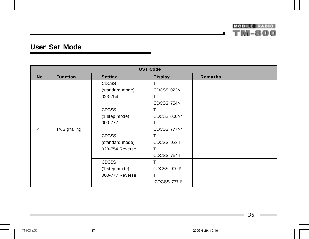
![UST CodeNo. Function Setting Display RemarksO f f R PF5: OFF/CTCSS/CDCSS OffCTCSS R [PF4]: Toggle between standard mode(EIA standard mode) CTCSS 67.0 and step mode67.0-254.1Hz R [PF3]: Toggle between CDCSS andCTCSS 254.1 reverse CDCSSCTCSS R(step: 0.1Hz) CTCSS 67.0*67.0-254.1Hz RCTCSS 254.1*CDCSS R(standard mode) CDCSS 023N023-754 RCDCSS 754NCDCSS R(1 step mode) CDCSS 000N*000-777 RCDCSS 777N*3RX Signalling34User Set ModeTM800.p65 2005-6-29, 10:1635](https://usermanual.wiki/HYT-Science-and-Technology-Co/TM-800V/User-Guide-558747-Page-35.png)
![UST CodeNo. Function Setting Display RemarksCDCSS R(standard mode) CDCSS 023¢ñ023-754 Reverse RCDCSS 754¢ñCDCSS R(1 step mode) CDCSS 000¢ñ*000-777 Reverse RCDCSS 777¢ñ*OFF T [PF5]: OFF/CTCSS/CDCSS OffCTCSS T PF4]: Toggle between standard mode(EIA standard mode) CTCSS 67.0 and step mode67.0-254.1Hz R [PF3]: Toggle between CDCSS andCTCSS 254.1 reverse CDCSSCTCSS T(step: 0.1Hz) CTCSS 67.0*67.0-254.1Hz TCTCSS 254.1*4 TX Signalling3RX Signalling35User Set ModeTM800.p65 2005-6-29, 10:1636](https://usermanual.wiki/HYT-Science-and-Technology-Co/TM-800V/User-Guide-558747-Page-36.png)
![¡ö¡ö¡ö¡ö¡ö Key AssignmentSelect “Key Assign” in the main menu and press the [PF6] key to program the programmable keys PF1-PF6 as following:Key AssignmentNo. Function Key Setting Display RemarksOff PF1 Off No functionVOL UP PF1 VOL UP Volume UpVOL Down PF1 VOL Down Volume DownCH Up PF1 CH Up Channel UpCH Down PF1 CH Down Channel DownZone Up PF1 Zone Up Zone UpZone Down PF1 Zone Down Zone DownMONI A PF1 MoniA Monitor A: Monitor Unmute-momentaryMONI B PF1 MoniB Monitor B: Monitor Unmute-ToggleMONI C (default) PF1 MoniC Monitor C: Carrier Squelch-momentaryMONI D PF1 MoniD Monitor D: Carrier Squelch-ToggleDisplayLabel PF1 DLabel Display channel labelDisplay Frequency PF1 Dfreq Display frequencyDisplay Mode PF1 Dmode Display toggles among channel number,channel label and channel frequencyUser Selectable Tone PF1 UserTone Tone 01-32 (CTCSS/CDCSS)Sel 2Tone PF1 Sel2Tone Select 2-Tone encode1[PF1]37User Set ModeTM800.p65 2005-6-29, 10:1638](https://usermanual.wiki/HYT-Science-and-Technology-Co/TM-800V/User-Guide-558747-Page-38.png)
![1[PF1]38User Set ModeAdd/Del PF1 Add/DelKey AssignmentNo. Function Key Setting Display RemarksSel 5Tone PF1 Sel5Tone Select 5-Tone encodeTX Power PF1 TXPower Switch transmit powerScan PF1 Scan ScanAdd/Del as not at scan statusTemporarily delete nuisance channelTemporarily delete priority channelReverse PF1 Reverse Reverse frequencyTalk Around PF1 TA Talk aroundSEL SQL PF1 SELSQL Select squelch levelHome CH PF1 HomeCH Home channelPublic Address PF1 PA Public addressHorn Alert PF1 HornAler Horn alertLCD Backlight PF1 LCDBL LCD backlightScrambler PF1 Scramble ScramblerCompander PF1 Compand CompanderAUX A PF1 AUX A AUX A Port output controlAUX B PF1 AUX B AUX B Port output controlSend GPS PF1 Send GPS Send GPSEmergency Call PF1 Emergency Emergency callMessage PF1 Message MessageTM800.p65 2005-6-29, 10:1639](https://usermanual.wiki/HYT-Science-and-Technology-Co/TM-800V/User-Guide-558747-Page-39.png)
![Key AssignmentNo. Function Key Setting Display RemarksOff PF2 Off No functionVOL UP PF2 VOL Up Increase volumeVOL Down PF2 VOL Down Decrease volumeCH Up PF2 CH Up Channel upCH Down PF2 CH Down Channel downZone Up PF2 Zone Up Zone upZone Down PF2 Zone Down Zone downMoniA PF2 MoniA Monitor A: Monitor Unmute-momentaryMoniB PF2 MoniB Monitor B: Monitor Unmute-ToggleMoniC PF2 MoniC Monitor C: Carrier Squelch-momentaryMoniD PF2 MoniD Monitor D: Carrier Squelch-ToggleDisplayLabel PF2 Dlabel Display channel labelDisplay Frequency PF2 DFreq Display frequencyDisplayMode [default] PF2 DMode Display toggles among channel number,channel label and channel frequencyUser Selectable Tone PF2 UserTone Tone 01-32 (CTCSS/CDCSS)Sel 2Tone PF2 Sel2Tone Select 2-Tone encodeSel 5Tone PF2 Sel5Tone Select 5-Tone encode2[PF2]39User Set ModeTM800.p65 2005-6-29, 10:1640](https://usermanual.wiki/HYT-Science-and-Technology-Co/TM-800V/User-Guide-558747-Page-40.png)
![Key AssignmentNo. Function Key Setting Display RemarksTX Power PF2 TXPower Switch transmit powerScan PF2 Scan ScanAdd/Del in non-scan modeTemporarily delete nuisance channelTemporarily delete priority channelReverse PF2 Reverse Reverse frequencyTalk Around PF2 TA Talk aroundSEL SQL PF2 SELSQL Select squelch levelHome CH PF2 HomeCH Home channelPublic Address PF2 PA Public addressHorn Alert PF2 HornAler Horn alertLCD Backlight PF2 LCDBL LCD backlightScrambler PF2 Scramble ScramblerCompander PF2 Compand CompanderAUX A PF2 AUX A AUXA Port output controlAUX B PF2 AUX B AUXB Port output controlSend GPS PF2 Send GPS Send GPSEmergency Call PF2 Emergency Emergency callMessage PF2 Message Message2[PF2]40User Set ModeAdd/Del PF2 Add/DelTM800.p65 2005-6-29, 10:1641](https://usermanual.wiki/HYT-Science-and-Technology-Co/TM-800V/User-Guide-558747-Page-41.png)
![Key AssignmentNo. Function Key Setting Display RemarksOff PF3 Off No functionVOL UP PF3 VOL Up Volume UpVOL Down PF3 VOL Down Volume DownCH Up PF3 CH Up Channel UpCH Down PF3 CH Down Channel DownZone Up PF3 Zone Up Zone UpZone Down PF3 Zone Down Zone DownMoniA PF3 MoniA Monitor A: Monitor Unmute-momentaryMoniB PF3 MoniB Monitor B: Monitor Unmute-ToggleMoniC PF3 MoniC Monitor C: Carrier Squelch-momentaryMoniD PF3 MoniD Monitor D: Carrier Squelch-ToggleDisplayLabel PF3 Dlabel Display channel labelDisplay Frequency PF3 DFreq Display frequencyDisplay Mode PF3 DMode Display toggles among channel number,channel label and channel frequencyUser Selectable Tone PF3 UserTone Tone 01-32 (CTCSS/CDCSS)Sel 2Tone PF3 Sel2Tone Select 2-Tone encodeSel 5Tone PF3 Sel5Tone Select 5-Tone encode3[PF3]41User Set ModeTM800.p65 2005-6-29, 10:1642](https://usermanual.wiki/HYT-Science-and-Technology-Co/TM-800V/User-Guide-558747-Page-42.png)
![Key AssignmentNo. Function Key Setting Display RemarksTX Power [default] PF3 TXPower Switch transmit powerScan PF3 Scan ScanAdd/Del as not at scan statusTemporarily delete nuisance channelTemporarily delete priority channelReverse PF3 Reverse Reverse frequencyTalk Around PF3 TA Talk aroundSEL SQL PF3 SELSQL Select squelch levelHome CH PF3 HomeCH Home channelPublic Address PF3 PA Public addressHorn Alert PF3 HornAler Horn alertLCD Backlight PF3 LCDBL LCD backlightScrambler PF3 Scramble ScramblerCompander PF3 Compand CompanderAUX A PF3 AUX A AUXA Port output controlAUX B PF3 AUX B AUXB Port output controlSend GPS PF3 Send GPS Send GPSEmergency Call PF3 Emergency Emergency callMessage PF3 Message Message3[PF3]42User Set ModeAdd/Del PF3 Add/DelTM800.p65 2005-6-29, 10:1643](https://usermanual.wiki/HYT-Science-and-Technology-Co/TM-800V/User-Guide-558747-Page-43.png)
![Key AssignmentNo. Function Key Setting Display RemarksOff PF4 Off No functionVOL UP PF4 VOL Up Volume UpVOL Down PF4 VOL Down Volume DownCH Up PF4 CH Up Channel UpCH Down PF4 CH Down Channel DownZone Up PF4 Zone Up Zone UpZone Down PF4 Zone Down Zone DownMoni A PF4 MoniA Monitor A: Monitor Unmute-momentaryMoni B PF4 MoniB Monitor B: Monitor Unmute-ToggleMoni C PF4 MoniC Monitor C: Carrier Squelch-momentaryMoni D PF4 MoniD Monitor D: Carrier Squelch-ToggleDisplayLabel PF4 Dlabel Display channel labelDisplay Frequency PF4 DFreq Display frequencyDisplay Mode PF4 DMode Display toggles among channel number,channel label and channel frequencyUser Selectable Tone PF4 UserTone Tone 01-32 (CTCSS/CDCSS)Sel 2Tone PF4 Sel2Tone Select 2-Tone encodeSel 5Tone PF4 Sel5Tone Select 5-Tone encode4[PF4]43User Set ModeTM800.p65 2005-6-29, 10:1644](https://usermanual.wiki/HYT-Science-and-Technology-Co/TM-800V/User-Guide-558747-Page-44.png)
![Key AssignmentNo. Function Key Setting Display RemarksTX Power PF4 TXPower Switch transmit powerScan [default] PF4 Scan ScanAdd/Del as not at scan statusTemporarily delete nuisance channelTemporarily delete priority channelReverse PF4 Reverse Reverse frequencyTalk Around PF4 TA Talk aroundSEL SQL PF4 SELSQL Select squelch levelHome CH PF4 HomeCH Home channelPublic Address PF4 PA Public addressHorn Alert PF4 HornAler Horn alertLCD Backlight PF4 LCDBL LCD backlightScrambler PF4 Scramble ScramblerCompander PF4 Compand CompanderAUX A PF4 AUX A AUXA Port output controlAUX B PF4 AUX B AUXB Port output controlSend GPS PF4 SendGPS Send GPSEmergency Call PF4 Emergency Emergency callMessage PF4 Message Message4[PF4]44User Set ModeAdd/Del PF4 Add/DelTM800.p65 2005-6-29, 10:1645](https://usermanual.wiki/HYT-Science-and-Technology-Co/TM-800V/User-Guide-558747-Page-45.png)
![Key AssignmentNo. Function Key Setting Display RemarksOff PF5 Off No functionVOL UP PF5 VOL Up Volume UpVOL Down PF5 VOL Down Volume DownCH Up PF5 CH Up Channel UpCH Down PF5 CH Down Channel DownZone Up PF5 Zone Up Zone UpZone Down [default] PF5 Zone Down Zone DownMoni A PF5 MoniA Monitor A: Monitor Unmute-momentaryMoni B PF5 MoniB Monitor B: Monitor Unmute-ToggleMoni C PF5 MoniC Monitor C: Carrier Squelch-momentaryMoni D PF5 MoniD Monitor D: Carrier Squelch-ToggleDisplayLabel PF5 Dlabel Display channel labelDisplay Frequency PF5 DFreq Display frequencyDisplay Mode PF5 DMode Display toggles among channel number,channel label and channel frequencyUser Selectable Tone PF5 UserTone Tone 01-32 (CTCSS/CDCSS)Sel 2Tone PF5 Sel2Tone Select 2-Tone encodeSel 5Tone PF5 Sel5Tone Select 5-Tone encode5[PF5]45User Set ModeTM800.p65 2005-6-29, 10:1646](https://usermanual.wiki/HYT-Science-and-Technology-Co/TM-800V/User-Guide-558747-Page-46.png)
![Key AssignmentNo. Function Key Setting Display RemarksTX Power PF5 TXPower Switch transmit powerScan PF5 Scan ScanAdd/Del as not at scan statusTemporarily delete nuisance channelTemporarily delete priority channelReverse PF5 Reverse Reverse frequencyTalk Around PF5 TA Talk aroundSEL SQL PF5 SELSQL Select squelch levelHome CH PF5 HomeCH Home channelPublic Address PF5 PA Public addressHorn Alert PF5 HornAler Horn alertLCD Backlight PF5 LCDBL LCD backlightScrambler PF5 Scramble ScramblerCompander PF5 Compand CompanderAUX A PF5 AUX A AUXA Port output controlAUX B PF5 AUX B AUXB Port output controlSend GPS PF5 SendGPS Send GPSEmergency Call PF5 Emergency Emergency callMessage PF5 Message Message5[PF5]46User Set ModeAdd/Del PF5 Add/DelTM800.p65 2005-6-29, 10:1647](https://usermanual.wiki/HYT-Science-and-Technology-Co/TM-800V/User-Guide-558747-Page-47.png)
![Key AssignmentNo. Function Key Setting Display RemarksOff PF6 Off No functionVOL UP PF6 VOL Up Volume UpVOL Down PF6 VOL Down Volume DownCH Up PF6 CH Up Channel UpCH Down PF6 CH Down Channel DownZone Up [default] PF6 Zone Up Zone UpZone Down PF6 Zone Down Zone DownMoni A PF6 MoniA Monitor A: Monitor Unmute-momentaryMoni B PF6 MoniB Monitor B: Monitor Unmute-ToggleMoni C PF6 MoniC Monitor C: Carrier Squelch-momentaryMoni D PF6 MoniD Monitor D: Carrier Squelch-ToggleDisplayLabel PF6 Dlabel Display channel labelDisplay Frequency PF6 DFreq Display frequencyDisplay Mode PF6 DMode Display toggles among channel number,channel label and channel frequencyUser Selectable Tone PF6 UserTone Tone 01-32 (CTCSS/CDCSS)Sel 2Tone PF6 Sel2Tone Select 2-Tone encodeSel 5Tone PF6 Sel5Tone Select 5-Tone encode6[PF6]47User Set ModeTM800.p65 2005-6-29, 10:1648](https://usermanual.wiki/HYT-Science-and-Technology-Co/TM-800V/User-Guide-558747-Page-48.png)
![Key AssignmentNo. Function Key Setting Display RemarksTX Power PF6 TXPower Switch transmit powerScan PF6 Scan ScanAdd/Del as not at scan statusTemporarily delete nuisance channelTemporarily delete priority channelReverse PF6 Reverse Reverse frequencyTalk Around PF6 TA Talk aroundSEL SQL PF6 SELSQL Select squelch levelHome CH PF6 HomeCH Home channelPublic Address PF6 PA Public addressHorn Alert PF6 HornAler Horn alertLCD Backlight PF6 LCDBL LCD backlightScrambler PF6 Scramble ScramblerCompander PF6 Compand CompanderAUX A PF6 AUX A AUXA Port output controlAUX B PF6 AUX B AUXB Port output controlSend GPS PF6 SendGPS Send GPSEmergency Call PF6 Emergency Emergency callMessage PF6 Message Message6 [PF6]48User Set ModeAdd/Del PF6 Add/DelTM800.p65 2005-6-29, 10:1649](https://usermanual.wiki/HYT-Science-and-Technology-Co/TM-800V/User-Guide-558747-Page-49.png)
![Key AssignmentNo. Function Key Setting Display RemarksVolume Knob [Default] Volume Knob Volume KnobChannel Knob Channel Knob Channel selector knobZone Knob Zone Knob Zone selector knobVolume Up/Down Volume UpDn Volume KnobChannel Up/Down [Default] Channel UpDn Channel selector knobZone Up/Down Zone UpDn Zone selector knobEND END Indicate the end of menu options789END[UP/Down][Selector Knob]49User Set ModeTM800.p65 2005-6-29, 10:1650](https://usermanual.wiki/HYT-Science-and-Technology-Co/TM-800V/User-Guide-558747-Page-50.png)
![Entering characters with an optional microphone keypadCHARACTERNumber of times key is pressed123 4 5 6 7 81 Space 12 A B C a b c 2 Each key can generate numeric3 D E F d e f 3 and character information.4 G H I g h i 4 Pressing a key will cause the5 J K L j k l 5 first character of the key’s6 M N O m n o 6 character cycle to appear on7 P Q R S p q r s 7 the LCD; Subsequent pressing8 T U V t u v 8 of the same key will cause9 W X Y Z w x y z 9 subsequent characters in the00 cycle to appear. For example,A @ ! # $ % ^ & ~ to enter the character “S”,B + - * / = \ _ | press the “7” key four (4) times.C( ) < > [ ] { }D, . ? : ; “ ‘ ‘* Press to toggle between number and character# Press to clear the inputPTT Enter (Complete programming and store)Appendix 1 Entering CharactersKEY NUMBER REMARKS50TM800.p65 2005-6-29, 10:1651](https://usermanual.wiki/HYT-Science-and-Technology-Co/TM-800V/User-Guide-558747-Page-51.png)
![Keypad Microphone Remote Control CableOptional AccessoriesEntering characters without a keypad1. Turn Selector Knob to choose the character to be entered.2. Press the [PF2] key to toggle among number, uppercaseletter, lowercase letter and symbol.3. Press the [PF3] / [PF4] key to move the cursor forward/backward.4. Press the [PF1] key to clear the input.5. Press the [PF6] key to confirm the input.Appendix 1 Entering Characters51 Control Head Remote KitTM800.p65 2005-6-29, 10:1652](https://usermanual.wiki/HYT-Science-and-Technology-Co/TM-800V/User-Guide-558747-Page-52.png)