HYUNDAI BS and C RMCU-COMPACT RMCU User Manual
HYUNDAI BS&C; Co.,Ltd RMCU
UserManual.wiki
>
HYUNDAI BS and C
>
RMCU COMPACT User Manual
User Manual
Navigation menu
Upload a User Manual
Namespaces
Wiki Guide
HTML
PDF
Info
Views
User Manual
Discussion / Help
Navigation
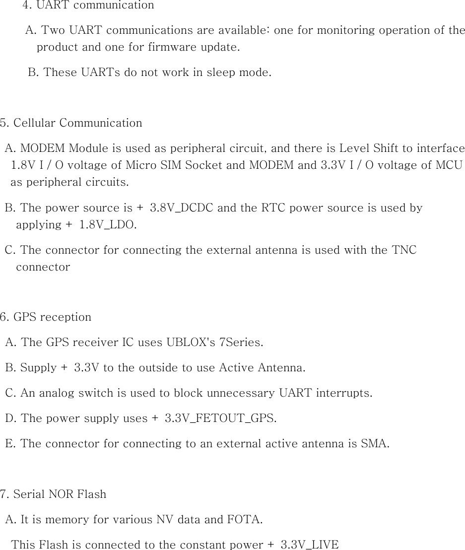
![I. Overview Remote Machine Control Unit (RMCU) consists of 3G communication module, GPS, Controller Area Network (CAN), Powersupply device, and Microcontroller. The 3G module provides wcdma, gsm communication and carries the information of the vehicle to the external server. The CAN obtain information of the vehicle while communicating with each Electronic Control Unit (ECU). The Microcontrolle controls the entire RMCU. [RMCU] II. General Specifications 1.1 Rated Voltage and Operating Temperature 1) Operating voltage: 12/24 [VDC] 2) Operating temperature: -30 ~ + 85 ℃](https://usermanual.wiki/HYUNDAI-BS-and-C/RMCU-COMPACT/User-Guide-3426034-Page-2.png)
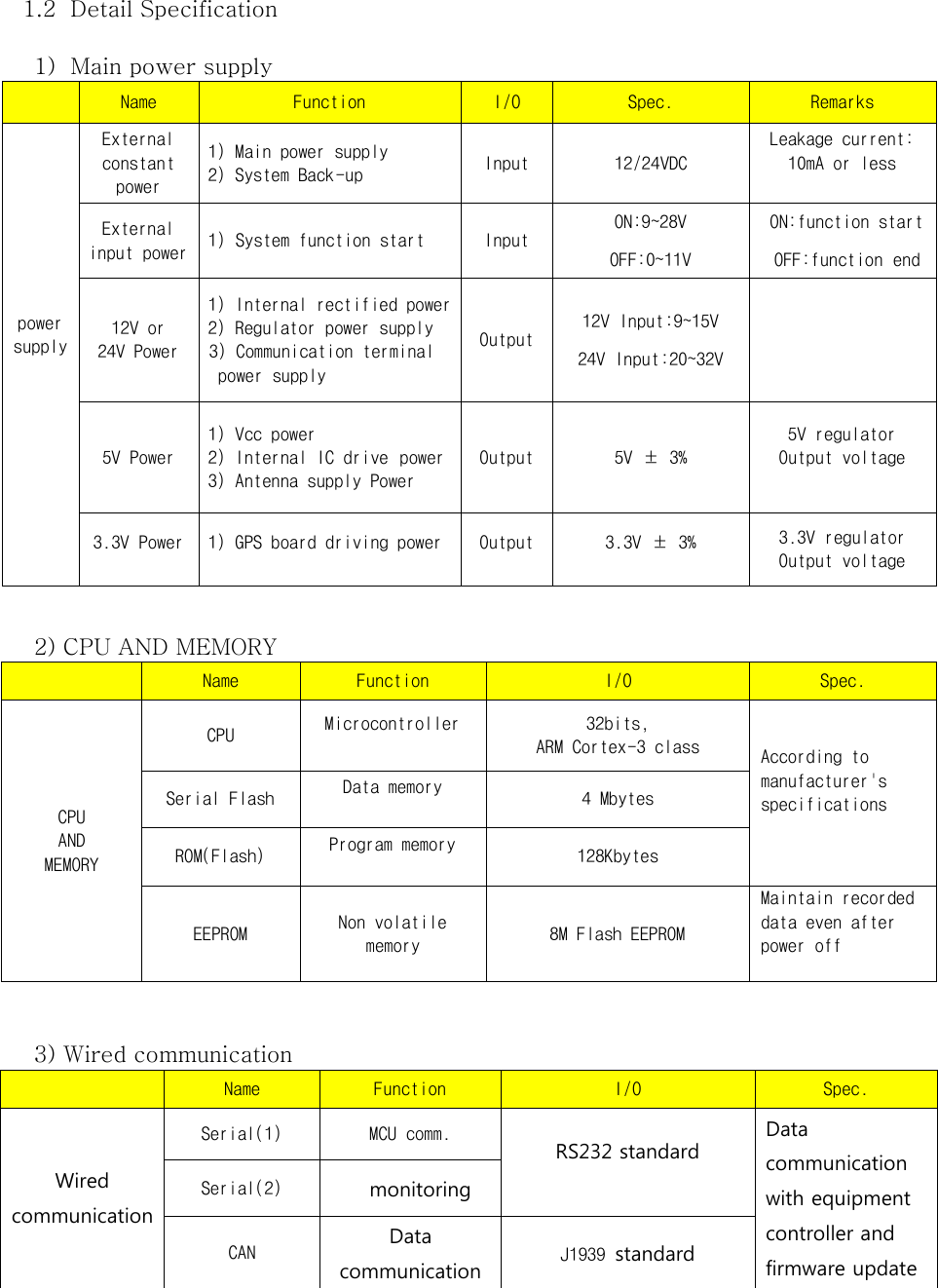
![4) Mobile communication Name Description Remark Mobile Coverage WCDMA Frequency UMTS-FDD (Uplink / Downlink) Band I (1920~1980 / 2110~2170 MHz) Band II (1850~1910 / 1930~1990 MHz) Band V (824~849 / 869~894 MHz) Band VI (830~840 / 875~885 MHz) Band VIII (880~915 / 925~960 MHz) GSM/EDGE (Uplink / Downlink) GSM850 (824.2~849.2 / 869.2~894.2 MHz) GSM900 (880~915 / 925~960 MHz) DCS1800 (1710.2~1784.8 / 1805.2~1879.8 MHz) PCS1900 (1850.2~1909.8 / 1930.2~1989.8 MHz) Uplink ≤5.76Mbps Downlink≤21Mbps SIM Chip type SIM(SMD Type) Add. function SMS / TCP / UDP / FTP GPS GPS L1 Receiver(GPS + GNASS) Connector Mobile TNC (Silver) GPS SMA (Gold) Main 14 Pin III. Pin Map Description No. Name Description 1 CAR_BATT1 Battery1 2 KEY_IGN Equipment IG 3 MONITOR_TX [RMCU->PC] Monitoring (TX) 4 MONITOR_RX [PC->RMCU] Monitoring (RX) 5 GND GND 6 GND GND 7 CAN_S CAN communication(Shield) 8 FW_EN F/W updated 9 MTS_TX [RMCU->MCU] Monitoring (TX) 10 MTS_RX [MCU->RMCU] Monitoring (RX) 11 CAN_H CAN communication (High) 12 CAN_L CAN communication (Low) 13 GND GND 14 CAR_BATT2 Battery 2](https://usermanual.wiki/HYUNDAI-BS-and-C/RMCU-COMPACT/User-Guide-3426034-Page-4.png)
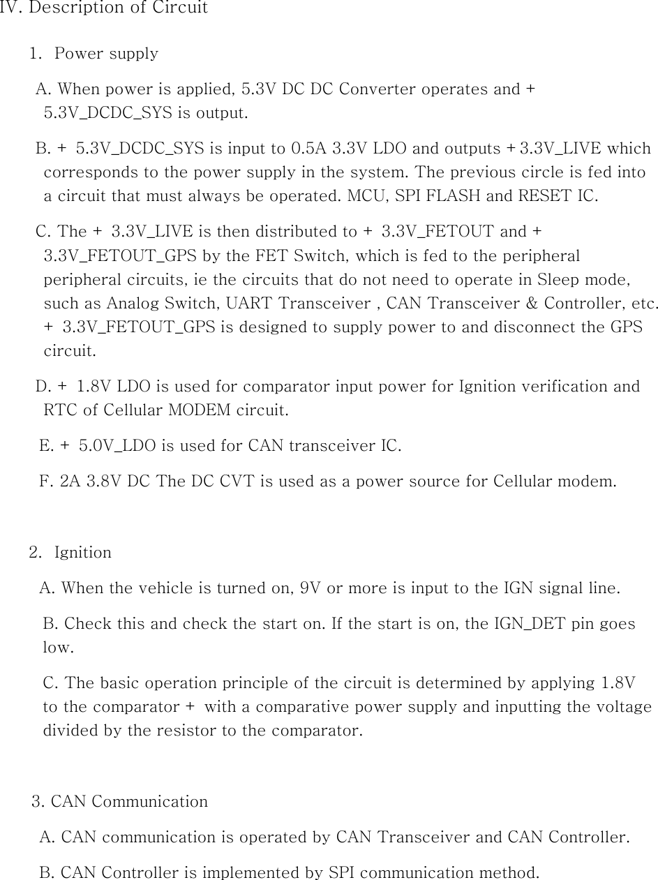
![V. Mechanical Drawings [Upper] [Lower]](https://usermanual.wiki/HYUNDAI-BS-and-C/RMCU-COMPACT/User-Guide-3426034-Page-7.png)