HYUNDAI BS and C RMCU-COMPACT RMCU User Manual
HYUNDAI BS&C; Co.,Ltd RMCU
User Manual
RMCU MANUAL
(Remote Machine Control Unit)
2017. 05
I. Overview
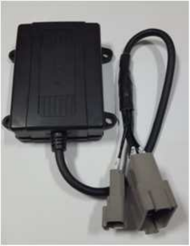
Remote Machine Control Unit (RMCU) consists of 3G communication module,
GPS, Controller Area Network (CAN), Powersupply device, and Microcontroller.
The 3G module provides wcdma, gsm communication and carries the information
of the vehicle to the external server. The CAN obtain information of the vehicle
while communicating with each Electronic Control Unit (ECU). The Microcontrolle
controls the entire RMCU.
[RMCU]
II. General Specifications
1.1 Rated Voltage and Operating Temperature
1) Operating voltage: 12/24 [VDC]
2) Operating temperature: -30 ~ + 85 ℃

1.2 Detail Specification
1) Main power supply
Name
Function
I/O
Spec.
Remarks
power
supply
External
constant
power
1) Main power supply
2) System Back-up
Input
12/24VDC
Leakage current:
10mA or less
External
input power
1) System function start
Input
ON:9~28V
OFF:0~11V
ON:function start
OFF:function end
12V or
24V Power
1) Internal rectified power
2) Regulator power supply
3) Communication terminal
power supply
Output
12V Input:9~15V
24V Input:20~32V
5V Power
1) Vcc power
2) Internal IC drive power
3) Antenna supply Power
Output
5V ± 3%
5V regulator
Output voltage
3.3V Power
1) GPS board driving power
Output
3.3V ± 3%
3.3V regulator
Output voltage
2) CPU AND MEMORY
Name
Function
I/O
Spec.
CPU
AND
MEMORY
CPU
Microcontroller
32bits,
ARM Cortex-3 class
According to
manufacturer's
specifications
Serial Flash
Data memory
4 Mbytes
ROM(Flash)
Program memory
128Kbytes
EEPROM
Non volatile
memory
8M Flash EEPROM
Maintain recorded
data even after
power off
3) Wired communication
Name
Function
I/O
Spec.
Wired
communication
Serial(1)
MCU comm.
RS232 standard
Data
communication
with equipment
controller and
firmware update
Serial(2)
monitoring
CAN
Data
communication
J1939 standard
4) Mobile communication
Name
Description
Remark
Mobile
Coverage
WCDMA
Frequency
UMTS-FDD (Uplink / Downlink)
Band I (1920~1980 / 2110~2170 MHz)
Band II (1850~1910 / 1930~1990 MHz)
Band V (824~849 / 869~894 MHz)
Band VI (830~840 / 875~885 MHz)
Band VIII (880~915 / 925~960 MHz)
GSM/EDGE (Uplink / Downlink)
GSM850 (824.2~849.2 / 869.2~894.2 MHz)
GSM900 (880~915 / 925~960 MHz)
DCS1800 (1710.2~1784.8 / 1805.2~1879.8 MHz)
PCS1900 (1850.2~1909.8 / 1930.2~1989.8 MHz)
Uplink ≤5.76Mbps
Downlink≤21Mbps
SIM
Chip type SIM(SMD Type)
Add. function
SMS / TCP / UDP / FTP
GPS
GPS L1 Receiver(GPS + GNASS)
Connector
Mobile
TNC (Silver)
GPS
SMA (Gold)
Main
14 Pin
III. Pin Map Description
No.
Name
Description
1
CAR_BATT1
Battery1
2
KEY_IGN
Equipment IG
3
MONITOR_TX
[RMCU->PC] Monitoring (TX)
4
MONITOR_RX
[PC->RMCU] Monitoring (RX)
5
GND
GND
6
GND
GND
7
CAN_S
CAN communication(Shield)
8
FW_EN
F/W updated
9
MTS_TX
[RMCU->MCU] Monitoring (TX)
10
MTS_RX
[MCU->RMCU] Monitoring (RX)
11
CAN_H
CAN communication (High)
12
CAN_L
CAN communication (Low)
13
GND
GND
14
CAR_BATT2
Battery 2
IV. Description of Circuit
1. Power supply
A. When power is applied, 5.3V DC DC Converter operates and +
5.3V_DCDC_SYS is output.
B. + 5.3V_DCDC_SYS is input to 0.5A 3.3V LDO and outputs +3.3V_LIVE which
corresponds to the power supply in the system. The previous circle is fed into
a circuit that must always be operated. MCU, SPI FLASH and RESET IC.
C. The + 3.3V_LIVE is then distributed to + 3.3V_FETOUT and +
3.3V_FETOUT_GPS by the FET Switch, which is fed to the peripheral
peripheral circuits, ie the circuits that do not need to operate in Sleep mode,
such as Analog Switch, UART Transceiver , CAN Transceiver & Controller, etc.
+ 3.3V_FETOUT_GPS is designed to supply power to and disconnect the GPS
circuit.
D. + 1.8V LDO is used for comparator input power for Ignition verification and
RTC of Cellular MODEM circuit.
E. + 5.0V_LDO is used for CAN transceiver IC.
F. 2A 3.8V DC The DC CVT is used as a power source for Cellular modem.
2. Ignition
A. When the vehicle is turned on, 9V or more is input to the IGN signal line.
B. Check this and check the start on. If the start is on, the IGN_DET pin goes
low.
C. The basic operation principle of the circuit is determined by applying 1.8V
to the comparator + with a comparative power supply and inputting the voltage
divided by the resistor to the comparator.
3. CAN Communication
A. CAN communication is operated by CAN Transceiver and CAN Controller.
B. CAN Controller is implemented by SPI communication method.
4. UART communication
A. Two UART communications are available: one for monitoring operation of the
product and one for firmware update.
B. These UARTs do not work in sleep mode.
5. Cellular Communication
A. MODEM Module is used as peripheral circuit, and there is Level Shift to interface
1.8V I / O voltage of Micro SIM Socket and MODEM and 3.3V I / O voltage of MCU
as peripheral circuits.
B. The power source is + 3.8V_DCDC and the RTC power source is used by
applying + 1.8V_LDO.
C. The connector for connecting the external antenna is used with the TNC
connector
6. GPS reception
A. The GPS receiver IC uses UBLOX's 7Series.
B. Supply + 3.3V to the outside to use Active Antenna.
C. An analog switch is used to block unnecessary UART interrupts.
D. The power supply uses + 3.3V_FETOUT_GPS.
E. The connector for connecting to an external active antenna is SMA.
7. Serial NOR Flash
A. It is memory for various NV data and FOTA.
This Flash is connected to the constant power + 3.3V_LIVE
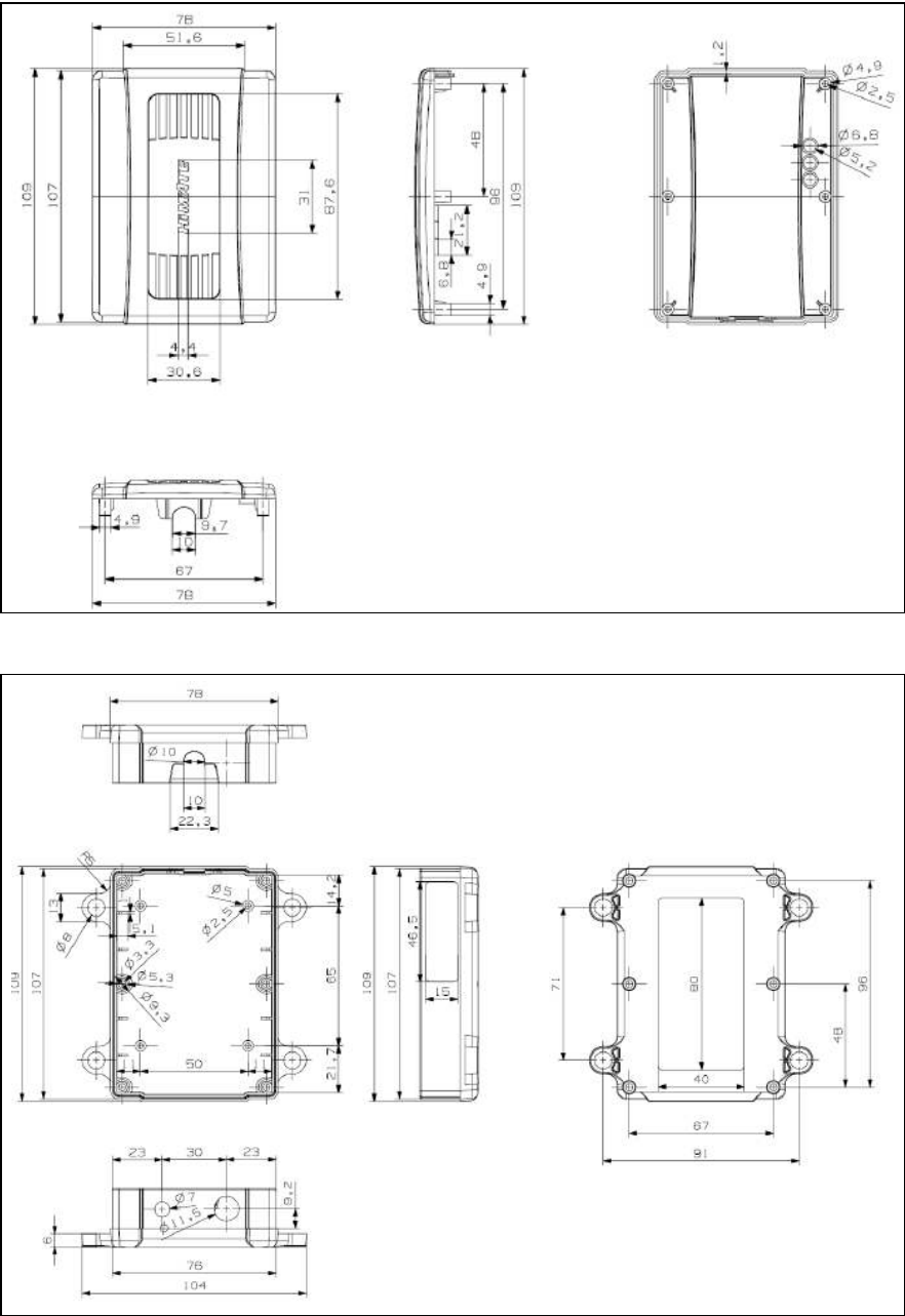
V. Mechanical Drawings
[Upper]
[Lower]