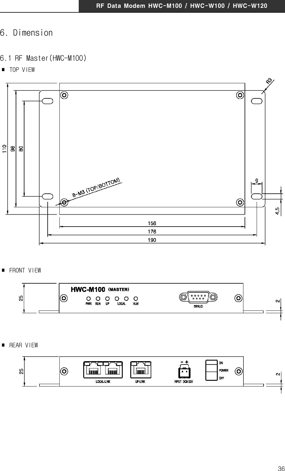
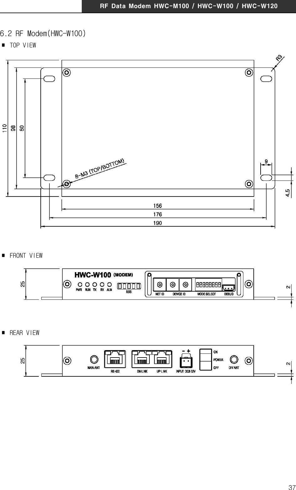
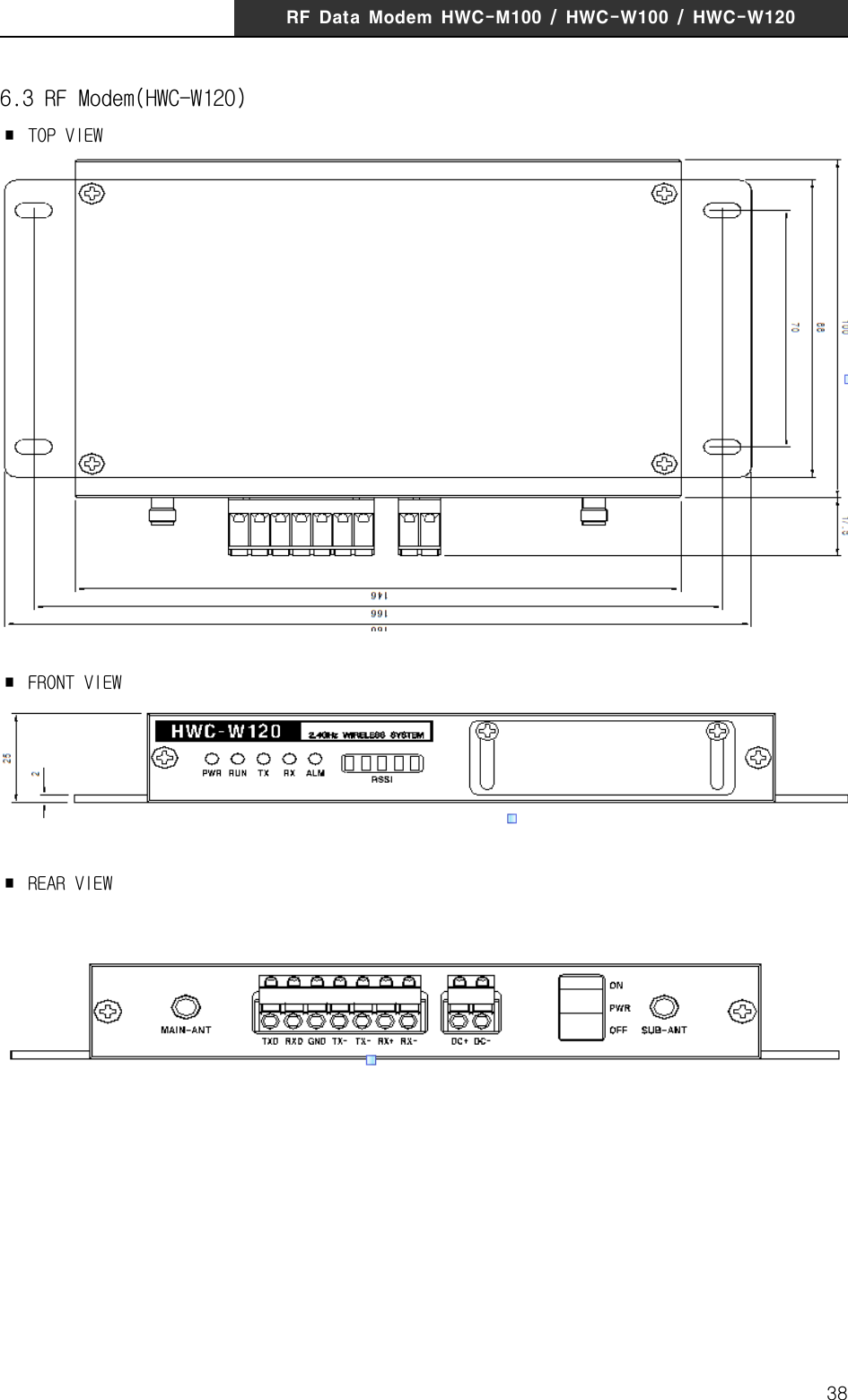
HYUNDAI ELEVATOR HWC-W120 RF Data Modem HWC-W120 User Manual rev hwp
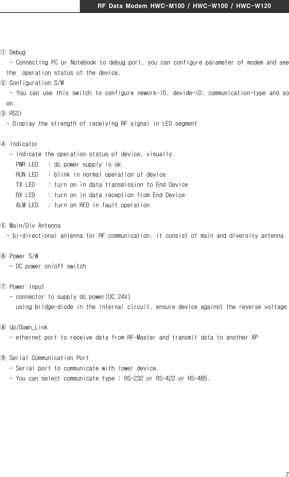
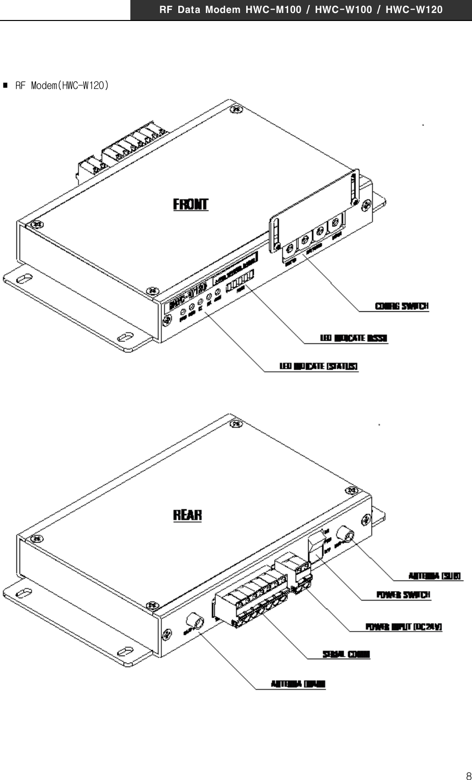
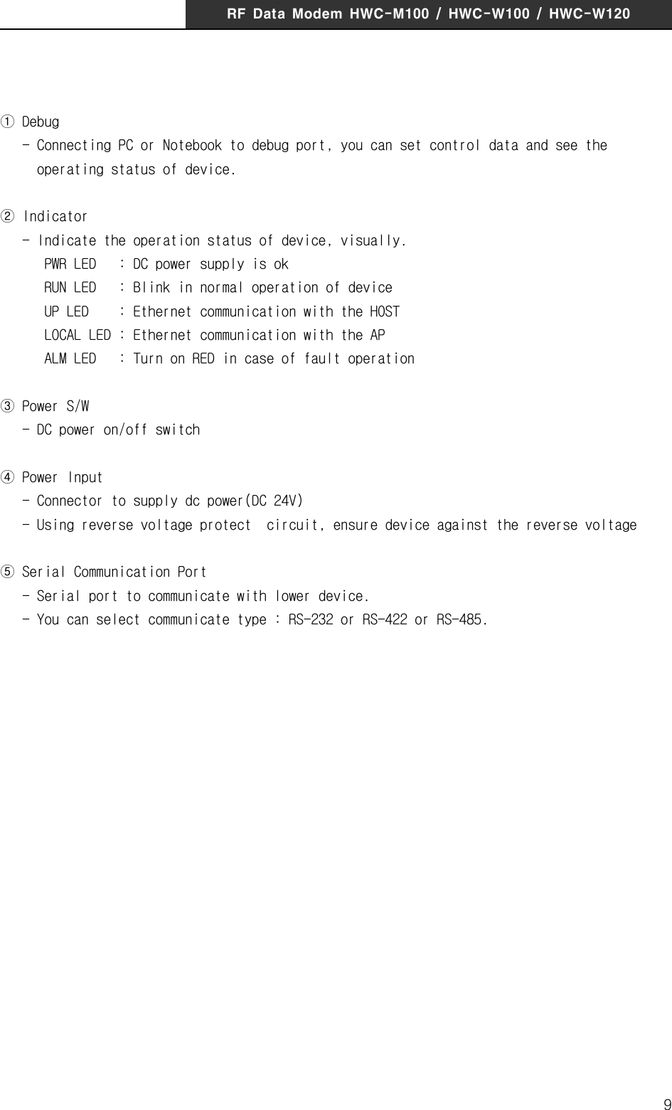
HYUNDAI ELEVATOR CO., LTD. RF Data Modem HWC-W120 rev hwp
UserManual.wiki
>
HYUNDAI ELEVATOR
>
HWC W120 User Manual
User Manual
Navigation menu
Upload a User Manual
Namespaces
Wiki Guide
HTML
PDF
Info
Views
User Manual
Discussion / Help
Navigation
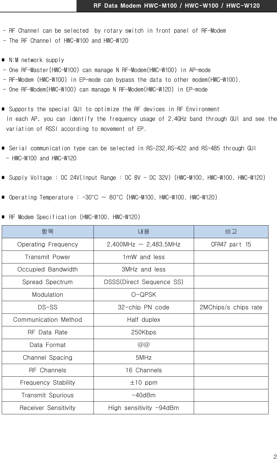
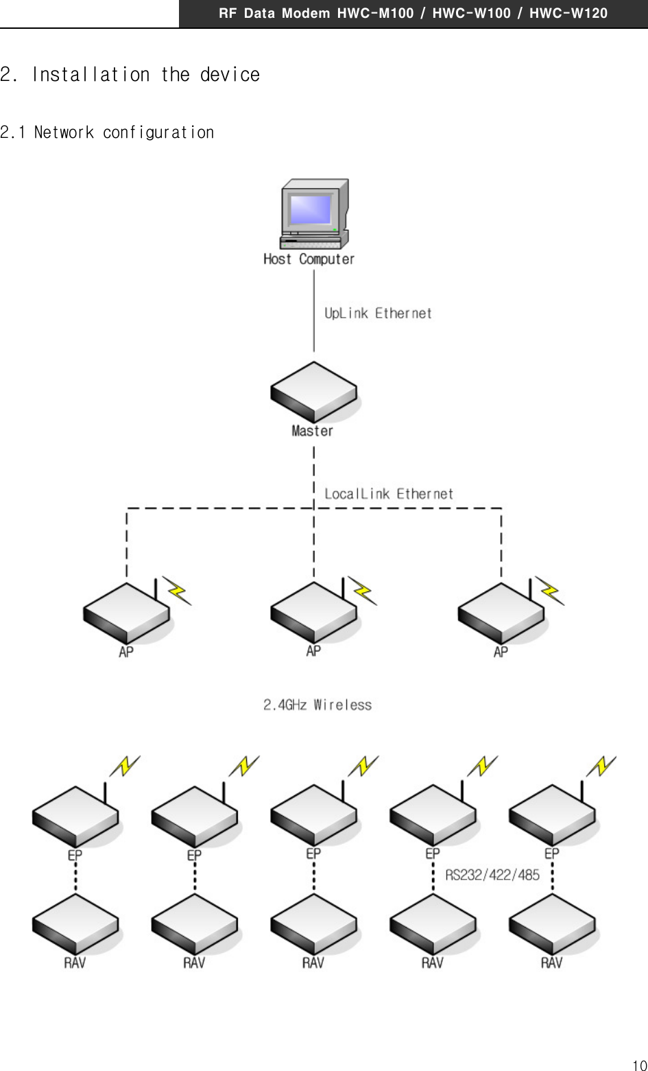
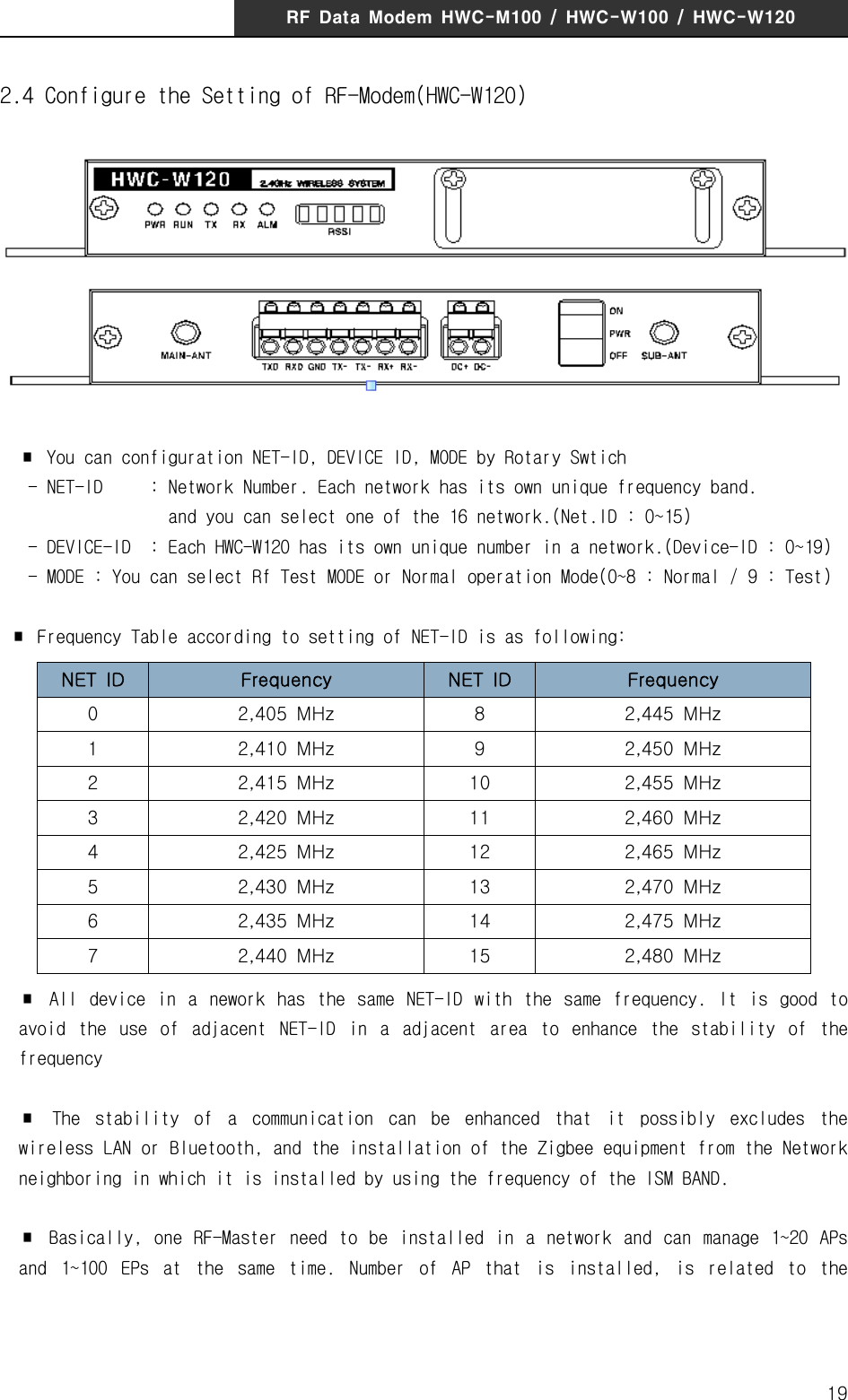
![RF Data Modem HWC-M100 / HWC-W100 / HWC-W12011. Overview1.1 Features∎ A license and qualification of application of the radio station are unnecessary.∎ RF Range - Indoor/Urban up to 75m(depending on environment) - Outdoor(line-of-sight) up to 300m∎ Communication Interface [RF Master(HWC-M100)] - Ethernet port(for Host) : 10/100Base-T, UDP - Serial port(for Debug) : RS-232(57600bps,8-N-1) - Interface with HWC-W100 through ethernet [RF Modem(HWC-W100)] - RS-232/422/485(for Device) : 4800~38400bps, 8-N-1 - Serial port(for Debug) : RS-232(57600bps,8-N-1) - Interface with HWC-W100 through ethernet - Interface with HWC-W120 through RF [RF Modem(HWC-W120)] - RS-232/422/485(for Device) : 4800~38400bps, 8-N-1 - Serial port(for Debug) : RS-232(57600bps,8-N-1) - Interface with HWC-W100 through RF∎ Wireless Interface - Based on the IEEE 802.15.4 DSSS(Direct Sequence Spread Spectrum) - ISM 2.4GHz operating frequency band∎ RF Modem Diversity(Antenna Diversity-Dedicated Receive Port) - Reduced the Multi-pass interference in the communication between moving-vehicles.∎ Interactive wireless communication - Half-duplex packet-communication based on Time-division-multiple-access - Supports the interactive communication between devices with RF-Modem∎ Supports up to 16 RF channels in the same area](https://usermanual.wiki/HYUNDAI-ELEVATOR/HWC-W120/User-Guide-2847026-Page-3.png)
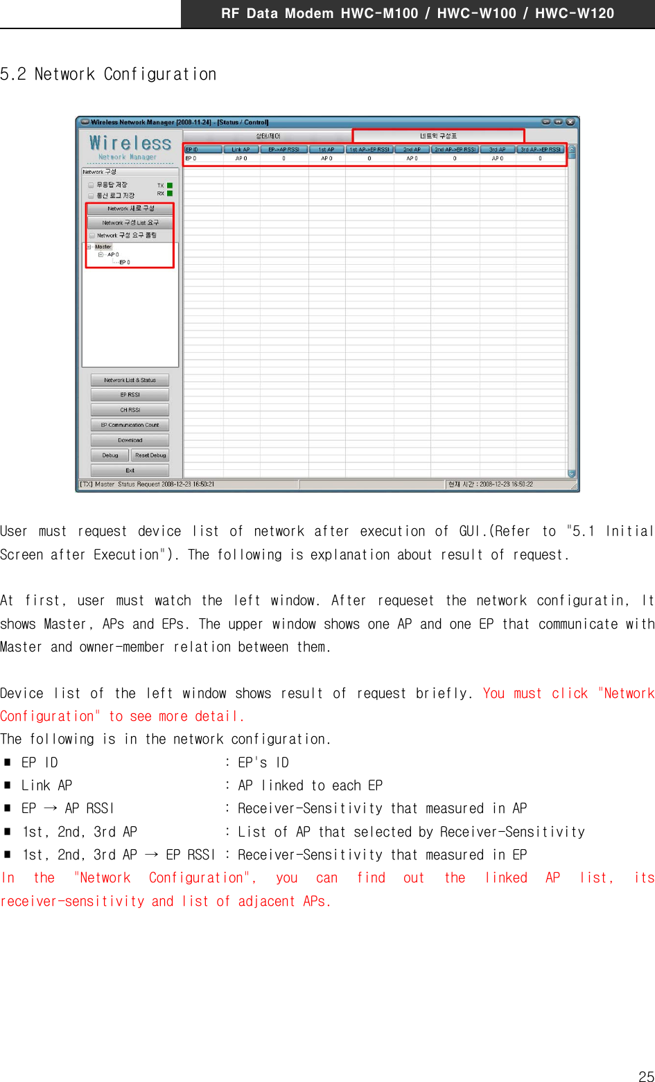
![RF Data Modem HWC-M100 / HWC-W100 / HWC-W120235. Quick Start for GUI5.1 Initial Screen after Execution When you execute the GUI program, the following screen is shown up.(In case of showing message about the setting of program, please refer to "5.11 Configure the setting of communication with device"! )This system consists of Master, AP and EP. As soon as excutuion, you can only see Master in left window. Therefore, user must request the list of device(AP, EP) by clicking [Configure Network] or [Request Device List].There is the following differences between [Configure Network] and [Request Device List].∎ [Configure Network] : It send commands to Master to gather the list of AP/EP again, Master begins to gather information and sends the progressing status and result to GUI.∎ [Request Device List] : It requests the device list that Master already gathers. Master sends the device list of AP/EP to GUI.Tip) After execution, It only show Master. If PC is not connected to Master, you couldn't see any AP/EP in left window because PC can't receive the device list. In other words, when PC is directly connected to AP/EP, PC can't receive any device list. In this case,](https://usermanual.wiki/HYUNDAI-ELEVATOR/HWC-W120/User-Guide-2847026-Page-25.png)

![RF Data Modem HWC-M100 / HWC-W100 / HWC-W120265.3 Status and Control of MasterIn upper screen, please confirm whether the "state/control" is selected. (If "status/control" is not selected, click the tab of "status/control")The following is the status information of Master. ∎ System Type : Type of system. ∎ Version : Firmware version of Master ∎ Host Link : Network information to communicate with HOST. These are network information of the Master. ∎ AP Link : Network information of communicate with AP. (User do not need to set this information.) ∎ Range of EP : Number of EP that installed. (Only by range)[Caution.1] When you want to see the status or control the value, "Network Polling" must not be checked. GUI program requests the network device list when "Network Polling" is checked and the status of selected device in other case, by periods. [Caution.2] If you couldn't see the upper screen, please confirm whether you select Master!](https://usermanual.wiki/HYUNDAI-ELEVATOR/HWC-W120/User-Guide-2847026-Page-28.png)
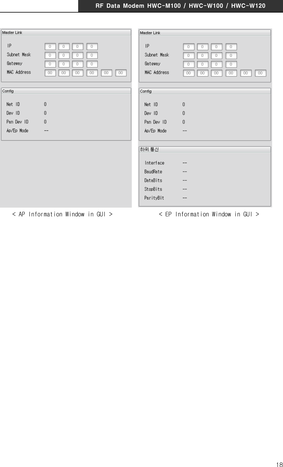
![RF Data Modem HWC-M100 / HWC-W100 / HWC-W120275.4 Status and control of APAfter selecting AP in device list, please confirm whether the "state/control" is selected (If "status/control" is not selected, click the tab of "status/control")The following is the status information of AP. ∎ System Type : Type of system. ∎ Version : Firmware version of AP. ∎ Master Link : Network information to communicate with Master. (User do not need to set this information.) ∎ Config : Configuration information of AP [Caution.1] When you want to see the status or control the value, "Network Polling" must not be checked. GUI program requests the network device list when "Network Polling" is checked and the status of selected device in other case, by periods. [Caution.2] If you couldn't see the upper screen, please confirm whether you select AP!](https://usermanual.wiki/HYUNDAI-ELEVATOR/HWC-W120/User-Guide-2847026-Page-29.png)
![RF Data Modem HWC-M100 / HWC-W100 / HWC-W120285.5 Status and Control of EPAfter selecting EP in device list, please confirm whether the "state/control" is selected (If "status/control" is not selected, click the tab of "status/control")The following is the status information of EP. ∎ System Type : Type of system. ∎ Version : Firmware version of EP. ∎ Master Link : Network information to communicate with Master. (User do not need to set this information.) ∎ Config : Configuration information of EP ∎ Comm. of End Device : Information of serial port to communicate with End-device ∎ EP Control : Item to control EP.[Caution.1] When you want to see the status or control the value, "Network Polling" must not be checked. GUI program requests the network device list when "Network Polling" is checked and the status of selected device in other case, by periods. [Caution.2] If you couldn't see the upper screen, please confirm whether you select EP!](https://usermanual.wiki/HYUNDAI-ELEVATOR/HWC-W120/User-Guide-2847026-Page-30.png)
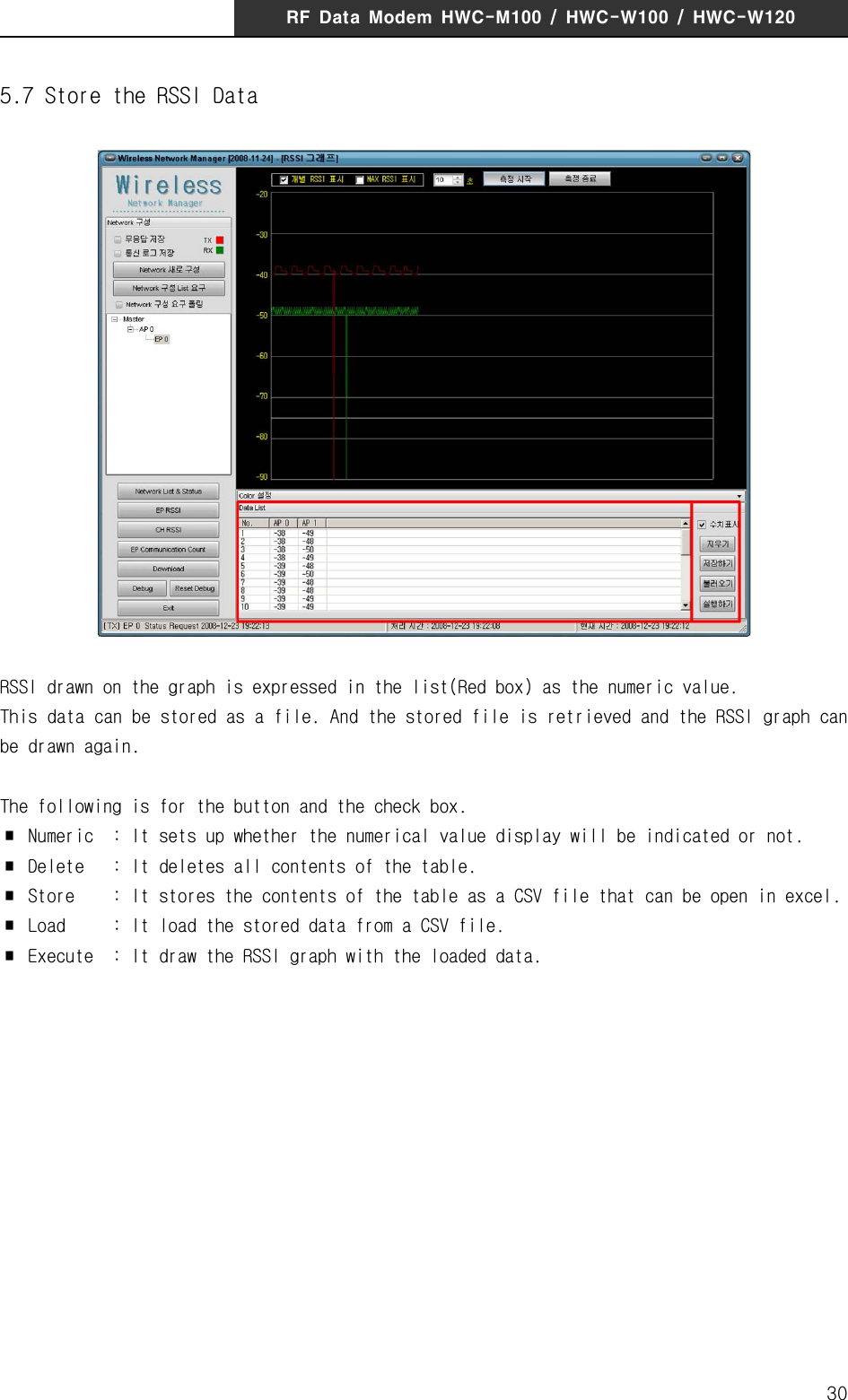
![RF Data Modem HWC-M100 / HWC-W100 / HWC-W120295.6 RSSI GraphThe Graph of RSSI visualizes the received signal strength between the installed AP and the selected EP. When it tries to determine whether the installation position of APs is appropriate or not, it will be useful. The following is the usage :1. Select the EP of the End-device that you want to see in left window.2. Click the check box for "Individual RSSI" and "MAX RSSI" Individual RSSI : display all of the RSSI value MAX RSSI : display the maximum value of each RSSI valule It is possible to select over 1 option.3. Set the time. It can set till a maximum 200 second, and this time means the X-axis. For example, If the time setting was 10 seconds, receiver-sensitivity data of 10 second amount is drawn on a screen. The time itself to measure is not limited to 10 seconds. Moreover, it is the setting about time interval to measure receiver-sensitivity data.The time interval is calculated by following formula : [Time interval for receiver-sensitivity data = time / 700]4. Start to move the End-device and measure. (click "Start measure")5. If the device does not communicate with any AP, finish to measure. and restart the measurement after changing the installation position of AP. (If the device does not communicate with any AP, it is not drawn on screen during that time. In this case, you must confirm the installation position of AP! )](https://usermanual.wiki/HYUNDAI-ELEVATOR/HWC-W120/User-Guide-2847026-Page-31.png)
![RF Data Modem HWC-M100 / HWC-W100 / HWC-W120335.10 DownloadThis is the function that upgrade the firmware of the deviceThe following is the usage :1. Select the device that is to be upgraded in the left list.2. Click the 'File Open’button and show up the dialog box. Click the 'OK' button after selecting the download file. (The file extension is MAU[Master], AP[RFU] and EP[RFU]. If the file extension is different, please confirm the device selected in left window)3. If the file is opened correctly, 'Download' button is activated. Press the button to begin to download.4. Download in Progress. If you would like to finish the download, press the "Stop" button 5. Complete to download. If it fails, try again!](https://usermanual.wiki/HYUNDAI-ELEVATOR/HWC-W120/User-Guide-2847026-Page-35.png)
![RF Data Modem HWC-M100 / HWC-W100 / HWC-W120345.11 Configure the setting of communication with deviceIn spite of executing the program after connecting the device with PC, If it is not communicated, The configuration of communication has to be confirmed. The following is the usage :1. Click the 'Debug' button in the main window.2. Check whether the received data "[RX] -------" is in the left window. You can use the 'start/stop' to start/stop the communication with the device. If there is not the received data "[RX] -----", please confirm the hardware connection.3. After checking the check box "Comport Close", you can change the configuration of communication.4. At first, confirm whether the PC is connected with the device through the serial cable or LAN cable. And select one of Serial/UDP.5. In case of serial, you must select and confirm the comport and baud-rate. In case of UDP, you must confirm the Target IP and Target Port. Target IP means the IP address of the device. Target Port must be always set to '9506'. The initial value of the polling Time is 1000, and the initial value of the waite time is 1500. It is recommended that is not changed.6. After the setting the communication configuration, Be sure to uncheck the check box 'Comport Close' and confirm the received data "[RX] -----" in the left side of the window. If there is not the received data, confirm whether the 'start' button is activated.](https://usermanual.wiki/HYUNDAI-ELEVATOR/HWC-W120/User-Guide-2847026-Page-36.png)
![RF Data Modem HWC-M100 / HWC-W100 / HWC-W12039[ A/S CENTER ]806 Ace Techno Tower 1st. 197-17 Guro3-Dong, Guro-Gu, Seoul, KoreaTel. +82-2-3281-9300Fax. +82-2-3281-7775FCCInformationtoUserThisequipmenthasbeentestedandfoundtocomplywiththelimitsforaClassBdigitaldevice, pursuant to Part 15 of the FCC Rules. These limits are designed to providereasonable protection against harmful interference in a residential installation. Thisequipmentgenerates,usesandcanradiateradiofrequencyenergyand,ifnotinstalledandused in accordance with the instructions, may cause harmful interference to radiocommunications. However, there is no guarantee that interference will not occur in aparticular installation.Ifthis equipmentdoes causeharmful interferencetoradio ortelevisionreception,whichcanbedeterminedbyturningtheequipmentoffandon,theuserisencouragedtotrytocorrecttheinterferencebyoneofthefollowingmeasures:•Reorientorrelocatethereceivingantenna.•Increasetheseparationbetweentheequipmentandreceiver.• Connect the equipment into an outlet on a circuit different fromthat towhichthereceiveriscon-nected.•Consultthedealeroranexperiencedradio/TVtechnicianforhelp.CautionModificationsnotexpresslyapprovedbythepartyresponsibleforcompliancecouldvoidtheuser’sauthoritytooperatetheequipment.FCC Compliance Information : This device complies with Part 15 of the FCC Rules.Operation is subject to the following two conditions: (1) This device may not causeharmfulinterference,and(2)thisdevicemustacceptanyinterferencereceived,includinginterferencethatmaycauseundesiredoperation](https://usermanual.wiki/HYUNDAI-ELEVATOR/HWC-W120/User-Guide-2847026-Page-41.png)