HYUNDAI ELEVATOR HWC-W120 RF Data Modem HWC-W120 User Manual rev hwp
HYUNDAI ELEVATOR CO., LTD. RF Data Modem HWC-W120 rev hwp
User Manual

RF Data Modem
HWC-M100
HWC-W100
HWC-W120
User Manual

RF Data Modem HWC-M100 / HWC-W100 / HWC-W120
Table of Contents
1. Overview
1.1 Features ㆍㆍㆍㆍㆍㆍㆍㆍㆍㆍㆍㆍㆍㆍㆍㆍㆍㆍㆍㆍㆍㆍㆍㆍㆍㆍㆍㆍㆍㆍㆍㆍ 1
1.2 Accessories ㆍㆍㆍㆍㆍㆍㆍㆍㆍㆍㆍㆍㆍㆍㆍㆍㆍㆍㆍㆍㆍㆍㆍㆍㆍㆍㆍㆍㆍㆍㆍㆍ 3
1.3 Product Description ㆍㆍㆍㆍㆍㆍㆍㆍㆍㆍㆍㆍㆍㆍㆍㆍㆍㆍㆍㆍㆍㆍㆍㆍㆍㆍㆍ 4
2. Installation the device
2.1 Network configuration ㆍㆍㆍㆍㆍㆍㆍㆍㆍㆍㆍㆍㆍㆍㆍㆍㆍㆍㆍㆍㆍㆍㆍㆍㆍㆍㆍ 10
2.2 Configure the Setting of RF-Master(HWC-M100) ㆍㆍㆍㆍㆍㆍㆍㆍㆍㆍㆍㆍㆍㆍㆍ 12
2.3 Configure the Setting of RF-Modem(HWC-W100) ㆍㆍㆍㆍㆍㆍㆍㆍㆍㆍㆍㆍㆍㆍㆍ14
2.4 Configure the Setting of RF-Modem(HWC-W120) ㆍㆍㆍㆍㆍㆍㆍㆍㆍㆍㆍㆍㆍㆍㆍ
3. Communication with HOST
3.1 Communication method ㆍㆍㆍㆍㆍㆍㆍㆍㆍㆍㆍㆍㆍㆍㆍㆍㆍㆍㆍㆍㆍㆍㆍㆍㆍㆍ 21
3.2 Communication data ㆍㆍㆍㆍㆍㆍㆍㆍㆍㆍㆍㆍㆍㆍㆍㆍㆍㆍㆍㆍㆍㆍㆍㆍㆍㆍ 21
4. Communication with the End Device
4.1 Communication Method ㆍㆍㆍㆍㆍㆍㆍㆍㆍㆍㆍㆍㆍㆍㆍㆍㆍㆍㆍㆍㆍㆍㆍㆍㆍ 22
4.2 Communication Data ㆍㆍ ㆍㆍㆍㆍㆍㆍㆍㆍㆍㆍㆍㆍㆍㆍㆍㆍㆍㆍㆍㆍㆍ 22
5. Quick Start for GUI
5.1 Initial Screen after Execution ㆍㆍㆍㆍㆍㆍㆍㆍㆍㆍㆍㆍㆍㆍㆍㆍㆍㆍㆍㆍ 23
5.2 Network Configuration ㆍㆍㆍㆍㆍㆍㆍㆍㆍㆍㆍㆍㆍㆍㆍㆍㆍㆍㆍㆍㆍㆍㆍ 25
5.3 Status and Control of Master ㆍㆍㆍㆍㆍㆍㆍㆍㆍㆍㆍㆍㆍㆍㆍㆍㆍㆍㆍㆍㆍㆍ 26
5.4 Status and control of AP ㆍㆍㆍㆍㆍㆍㆍㆍㆍㆍㆍㆍㆍㆍㆍㆍㆍㆍㆍㆍㆍㆍ 27
5.5 Status and Control of EP ㆍㆍㆍㆍㆍㆍㆍㆍㆍㆍㆍㆍㆍㆍㆍㆍㆍㆍㆍㆍㆍㆍ 28
5.6 RSSI Graph ㆍㆍㆍㆍㆍㆍㆍㆍㆍㆍㆍㆍㆍㆍㆍㆍㆍㆍㆍㆍㆍㆍㆍㆍㆍㆍㆍㆍ 29
5.7 Store the RSSI Data ㆍㆍㆍㆍㆍㆍㆍㆍㆍㆍㆍㆍㆍㆍㆍㆍㆍㆍㆍㆍㆍㆍㆍㆍㆍ 30
5.8 CH RSSI ㆍㆍㆍㆍㆍㆍㆍㆍㆍㆍㆍㆍㆍㆍㆍㆍㆍㆍㆍㆍㆍㆍㆍㆍㆍㆍㆍㆍㆍㆍㆍ 31
5.9 EP Communication Count ㆍㆍㆍㆍㆍㆍㆍㆍㆍㆍㆍㆍㆍㆍㆍㆍㆍㆍㆍㆍㆍㆍ 32
5.10 Download ㆍㆍㆍㆍㆍㆍㆍㆍㆍㆍㆍㆍㆍㆍㆍㆍㆍㆍㆍㆍㆍㆍㆍㆍㆍㆍㆍㆍㆍ 33
5.11 Configure the setting of communication with device ㆍㆍㆍㆍㆍㆍㆍㆍㆍㆍㆍ 34
5.12 Others ㆍㆍㆍㆍㆍㆍㆍㆍㆍㆍㆍㆍㆍㆍㆍㆍㆍㆍㆍㆍㆍㆍㆍㆍㆍㆍㆍㆍㆍ 35
6. Dimension
6.1 RF Master(HWC-M100) ㆍㆍㆍㆍㆍㆍㆍㆍㆍㆍㆍㆍㆍㆍㆍㆍㆍㆍㆍㆍㆍㆍㆍ 36
6.2 RF Modem(HWC-W100) ㆍㆍㆍㆍㆍㆍㆍㆍㆍㆍㆍㆍㆍㆍㆍㆍㆍㆍㆍㆍㆍㆍㆍ 37
6.3 RF Modem(HWC-W120) ㆍㆍㆍㆍㆍㆍㆍㆍㆍㆍㆍㆍㆍㆍㆍㆍㆍㆍㆍㆍㆍㆍㆍ 38

RF Data Modem HWC-M100 / HWC-W100 / HWC-W120
1
1. Overview
1.1 Features
∎ A license and qualification of application of the radio station are unnecessary.
∎ RF Range
- Indoor/Urban up to 75m(depending on environment)
- Outdoor(line-of-sight) up to 300m
∎ Communication Interface
[RF Master(HWC-M100)]
- Ethernet port(for Host) : 10/100Base-T, UDP
- Serial port(for Debug) : RS-232(57600bps,8-N-1)
- Interface with HWC-W100 through ethernet
[RF Modem(HWC-W100)]
- RS-232/422/485(for Device) : 4800~38400bps, 8-N-1
- Serial port(for Debug) : RS-232(57600bps,8-N-1)
- Interface with HWC-W100 through ethernet
- Interface with HWC-W120 through RF
[RF Modem(HWC-W120)]
- RS-232/422/485(for Device) : 4800~38400bps, 8-N-1
- Serial port(for Debug) : RS-232(57600bps,8-N-1)
- Interface with HWC-W100 through RF
∎ Wireless Interface
- Based on the IEEE 802.15.4 DSSS(Direct Sequence Spread Spectrum)
- ISM 2.4GHz operating frequency band
∎ RF Modem Diversity(Antenna Diversity-Dedicated Receive Port)
- Reduced the Multi-pass interference in the communication between moving-vehicles.
∎ Interactive wireless communication
- Half-duplex packet-communication based on Time-division-multiple-access
- Supports the interactive communication between devices with RF-Modem
∎ Supports up to 16 RF channels in the same area
RF Data Modem HWC-M100 / HWC-W100 / HWC-W120
2
- RF Channel can be selected by rotary switch in front panel of RF-Modem
- The RF Channel of HWC-W100 and HWC-W120
∎ N:M network supply
- One RF-Master(HWC-M100) can manage N RF-Modem(HWC-W100) in AP-mode
- RF-Modem (HWC-W100) in EP-mode can bypass the data to other modem(HWC-W100).
- One RF-Modem(HWC-W100) can manage N RF-Modem(HWC-W120) in EP-mode
∎ Supports the special GUI to optimize the RF devices in RF Environment
In each AP, you can identify the frequency usage of 2.4GHz band through GUI and see the
variation of RSSI according to movement of EP.
∎ Serial communication type can be selected in RS-232,RS-422 and RS-485 through GUI
- HWC-W100 and HWC-W120
∎ Supply Voltage : DC 24V(Input Range : DC 8V ~ DC 32V) (HWC-M100, HWC-W100, HWC-W120)
∎ Operating Temperature : -30°C ~ 80°C (HWC-M100, HWC-W100, HWC-W120)
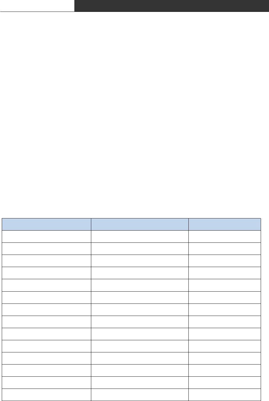
∎ RF Modem Specification (HWC-W100, HWC-W120)
항목 내용 비고
Operating Frequency 2,400MHz ~ 2,483.5MHz CFR47 part 15
Transmit Power 1mW and less
Occupied Bandwidth 3MHz and less
Spread Spectrum DSSS(Direct Sequence SS)
Modulation O-QPSK
DS-SS 32-chip PN code 2MChips/s chips rate
Communication Method Half duplex
RF Data Rate 250Kbps
Data Format @@
Channel Spacing 5MHz
RF Channels 16 Channels
Frequency Stability ±10 ppm
Transmit Spurious -40dBm
Receiver Sensitivity High sensitivity -94dBm

RF Data Modem HWC-M100 / HWC-W100 / HWC-W120
3
1.2 Accessories
∎ RF Master(HWC-M100)
∎ RF Modem(HWC-W100)
∎ RF Master(HWC-W120)
RF Data Modem HWC-M100 / HWC-W100 / HWC-W120
4
1.3 Product Description
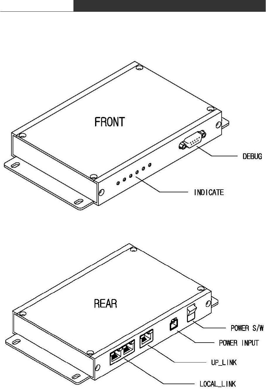
∎ RF Master(HWC-M100)

RF Data Modem HWC-M100 / HWC-W100 / HWC-W120
5
① Debug
- Connecting PC or Notebook to debug port, you can set control data and see the
operating status of device.
② Indicator
- Indicate the operation status of device, visually.
PWR LED : DC power supply is ok
RUN LED : Blink in normal operation of device
UP LED : Ethernet communication with the HOST
LOCAL LED : Ethernet communication with the AP
ALM LED : Turn on RED in case of fault operation
③ Power S/W
- DC power on/off switch
④ Power Input
- Connector to supply dc power(DC 24V)
- Using reverse voltage protect circuit, ensure device against the reverse voltage
⑤ Up_Link
- Ethernet port to communicate with upper HOST
⑥ Local_Link
- Ethernet port to communicate with lower AP
RF Data Modem HWC-M100 / HWC-W100 / HWC-W120
6
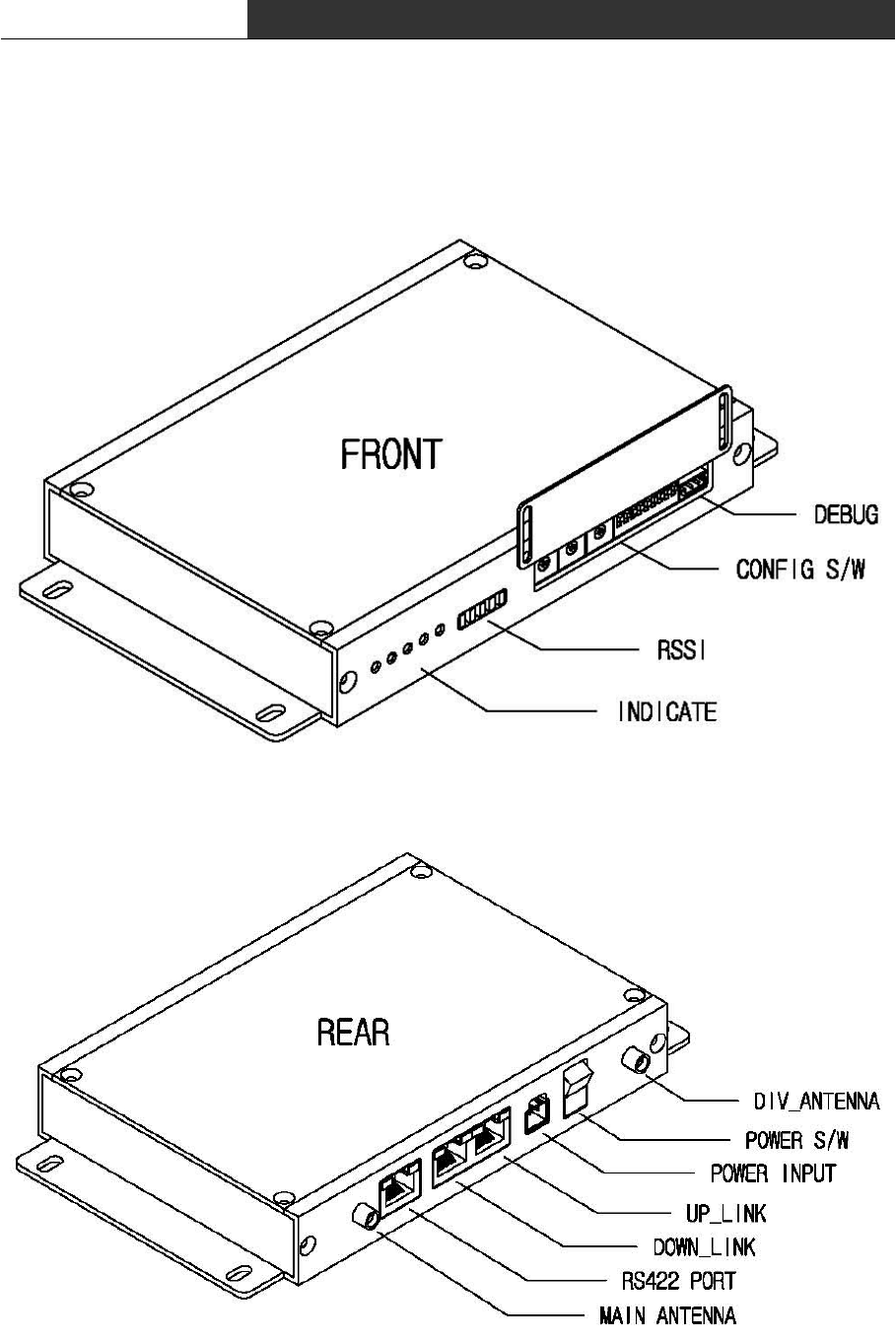
∎ RF Modem(HWC-W100)

RF Data Modem HWC-M100 / HWC-W100 / HWC-W120
7
① Debug
- Connecting PC or Notebook to debug port, you can configure parameter of modem and see
the operation status of the device.
② Configuration S/W
- You can use this switch to configure nework-ID, devide-ID, communication-type and so
on.
③ RSSI
- Display the strength of receiving RF signal in LED segment
④ Indicator
- Indicate the operation status of device, visually.
PWR LED : dc power supply is ok
RUN LED : blink in normal operation of device
TX LED : turn on in data transmission to End Device
RX LED : turn on in data reception from End Device
ALM LED : turn on RED in fault operation
⑤ Main/Div Antenna
- bi-directional antenna for RF communication. It consist of main and diversity antenna.
⑥ Power S/W
- DC power on/off switch
⑦ Power Input
- connector to supply dc power(DC 24V)
using bridge-diode in the internal circuit, ensure device against the reverse voltage
⑧ Up/Down_Link
- ethernet port to receive data from RF-Master and transmit data to another AP
⑨ Serial Communication Port
- Serial port to communicate with lower device.
- You can select communicate type : RS-232 or RS-422 or RS-485.
RF Data Modem HWC-M100 / HWC-W100 / HWC-W120
8
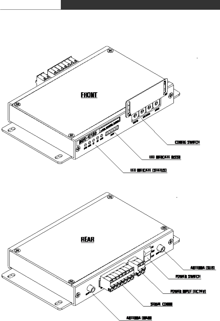
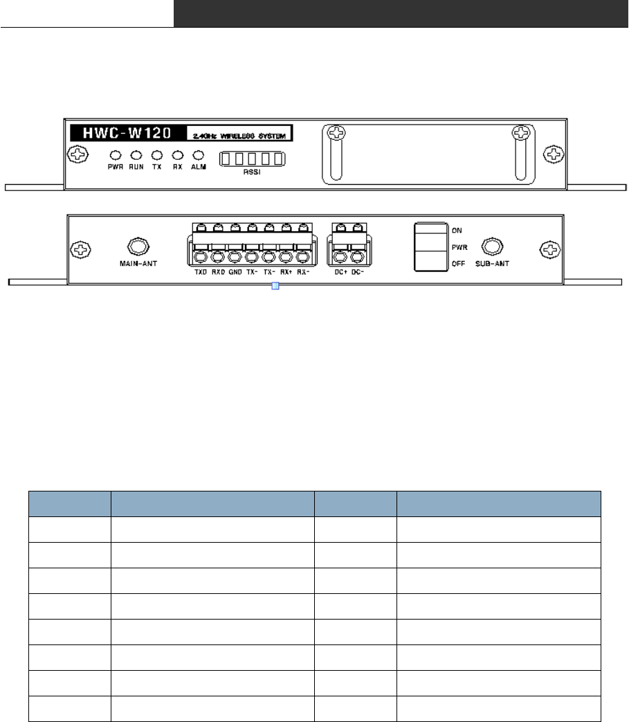
∎ RF Modem(HWC-W120)

RF Data Modem HWC-M100 / HWC-W100 / HWC-W120
9
① Debug
- Connecting PC or Notebook to debug port, you can set control data and see the
operating status of device.
② Indicator
- Indicate the operation status of device, visually.
PWR LED : DC power supply is ok
RUN LED : Blink in normal operation of device
UP LED : Ethernet communication with the HOST
LOCAL LED : Ethernet communication with the AP
ALM LED : Turn on RED in case of fault operation
③ Power S/W
- DC power on/off switch
④ Power Input
- Connector to supply dc power(DC 24V)
- Using reverse voltage protect circuit, ensure device against the reverse voltage
⑤ Serial Communication Port
- Serial port to communicate with lower device.
- You can select communicate type : RS-232 or RS-422 or RS-485.
RF Data Modem HWC-M100 / HWC-W100 / HWC-W120
10
2. Installation the device
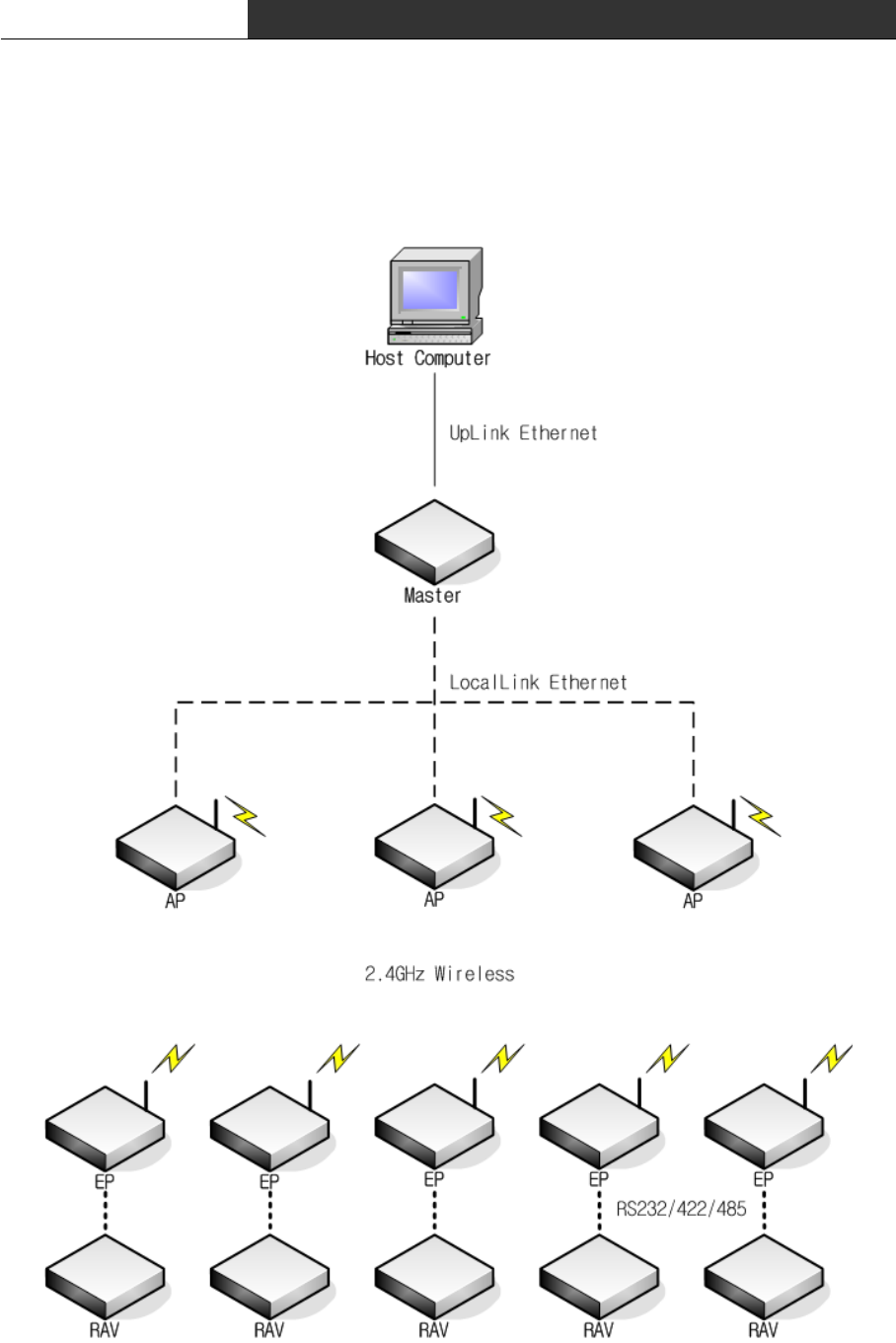
2.1 Network configuration

RF Data Modem HWC-M100 / HWC-W100 / HWC-W120
11
∎ The network consists of one RF-Master(HWC-M100) and several AP(Access Point)/EP(End
Point)
∎ You can set AP(Access Point) or EP(End Point) mode of RF Master(HWC-M100) using
configuration-Switch.
∎ Communication between HOST and RF-Master can be implemented in public or private
network.
∎ One RF-Master can be connected to several AP in ethernet communication. It can be
implemented in multi-drop bus for interconnecting RF-Master and APs.
∎ RF-Master manages network that relays the communication of HOST and lower equipment.
∎ AP(Access poing) Managed by RF-Master relays data in which Host delivers to EP. When
the shadow region exists with a AP, AP can be additionally installed and the coverage can
be expanded.
∎ EP(End Point) is connected with a subordinate equipment by wire and supports a
communication with HOST. You can select one of the RS232/RS422/RS485 to communicate with
the lower equipment.
RF Data Modem HWC-M100 / HWC-W100 / HWC-W120
12
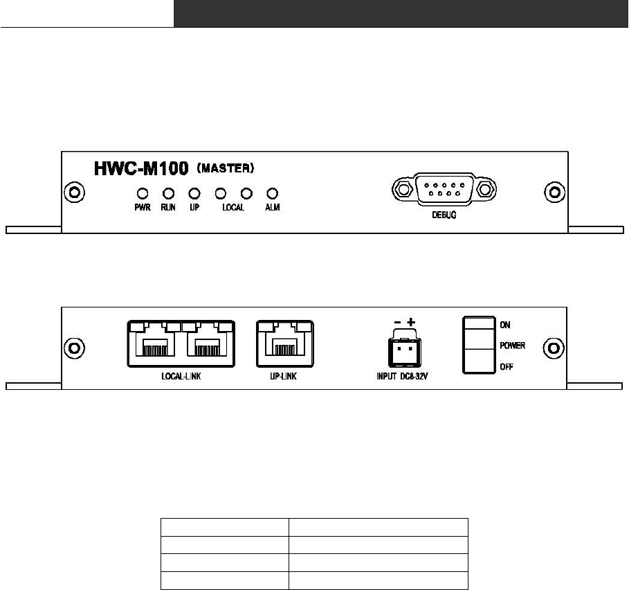
2.2 Configure the Setting of RF-Master(HWC-M100)
< Front View >
< Rear View >
∎ DEBUG : You can configure RF-Master through the debug-port using special GUI in PC or
notebook. The debug-port supports RS-232C interface(57600 bsp, 8 bit data, None parity,
1stop).
Pin Number Description
2TXD
3RXD
5GND
< Pin description of Debug-Port >
∎ RF-Master has two ethernet network. One is to link the upper Host, another is to link
the lower APs.
∎ UP-LINK : RF-Master could be connected using LAN cable with upper device(HOST)
through RJ-45 connector(UP-LINK) in rear panel of device.
∎ LOCAL-LINK : This port(LOCAL-LINK) is used for communication with lower device(AP).
RF-Master has 2 channel Ethernet hub inside in it. So you can extend APs without any
external Ethernet hub.
∎ Ethernet communication between HOST and RF-Master(UP-LINK) can be implemented in
public or private network. and AP can use in the private network that configured in
production.
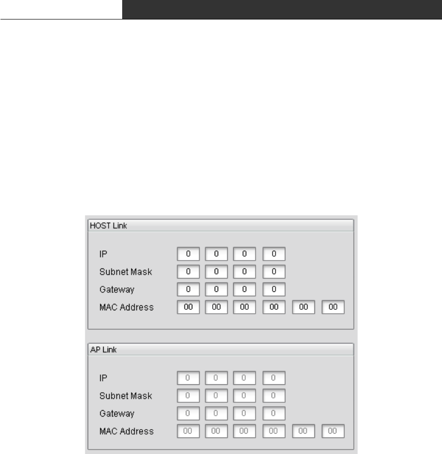
Each ethernet network is configured as following:
RF Data Modem HWC-M100 / HWC-W100 / HWC-W120
13
- UP-LINK : IP Address, Subnet Mask, Gateway Address, MAC Address
(MAC Address is assigned when RF-Master is producted. If RF-Master has no MAC address,
you can re-assign by the address printed on sticker that attached on PCB.)
- LOCAL-LINK : You don't need to set Ethernet network parameter for AP.
It is fixed as following:
IP Address : 192.168.10.1
Subnet Mask : 255.255.255.0
Gateway : 192.168.10.254
MAC Address : 00:0A:1F:00:EC:01
<Network Parameter Window in GUI>
∎ Start-up procedure of RF-Master
① Supply power(8~32VDC)
② Connect ethernet cable to UP-LINK Port(connection with Host)
③ Connect ethernet cable to LOCAL-LINK Port(connection with AP)
④ Turn on the power switch
⑤ Confirm that PWR-LED is ON
⑥ Connect with PC or note-book through Debug-port
⑦ Execute the GUI program.
⑧ Enter the IP Address, Subnet Mask and Gateway Address in Host-Link Window.
⑨ Confirm that UP-LED is ON.(ethernet link with HOST)
⑩ Confirm that LOCAL-LED is ON.(ethernet link with AP)
RF Data Modem HWC-M100 / HWC-W100 / HWC-W120
14
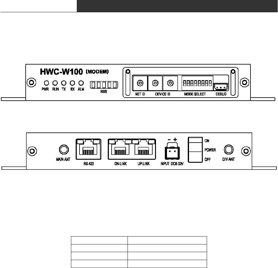
2.3 Configure the Setting of RF-Modem(HWC-W100)
< Front View >
< Rear View >
∎ You can configure Net-ID, Device-ID and Mode of RF-Modem using switches. And you can
confirm the configuration information in special GUI. The debug-port supports RS-232C
interface(57600 bsp, 8 bit data, None parity, 1stop).
Pin Number Description
1TXD
2RXD
3GND
< Pin description of Debug-Port >
∎ RF-Modem relays data in which Host delivers to the End-Device by wireless. And It can
be used as AP(to communicate with Host) or EP(to communicate with End-Device) by selection
of dip-switch in front panel of it.
∎ In AP-mode, you need to set Net-ID, Device-ID, AP/EP-Mode as follows:
- NET-ID : Network Number. Each network has its own unique frequency band.
and you can select one of the 16 network.(Net.ID : 0~15)
- DEVICE-ID : Device-ID of the AP. Each AP has its own unique number in a network.
and you can select one of the 20 APs.(Device-ID : 0~19)
- AP/EP-Mode : You must turn the dip-switch for AP/EP-mode to ON.
∎ In AP-mode, you need to set Net-ID, Device-ID, Baud-rate, data-bit, stop-bit,
parity-bit, interface-type and AP/EP-Mode as follows:
RF Data Modem HWC-M100 / HWC-W100 / HWC-W120
15
- NET-ID : Network Number. Each network has its own unique frequency band.
and you can select one of the 16 network.(Net.ID : 0~15)
- DEVICE-ID : Device-ID of the EP. Each EP has its own unique number in a network.
and you can select one of the 100 EPs.(Device-ID : 0~99)
- BAUDRATE : Baud-rate of interface between EP and End Device(4800~38400Bps)
- DATA BIT : Length of Data-bit(7 or 8 bits)
- STOP BIT : Length of Stop-bit(1 or 2 bits)
- PARITY BIT : Selection of use of parity-bit(even or none)
- INTERFACE : Type of Interface between EP and End-Device.(RS232/RS485/RS422)
- AP/EP Mode : You must turn the dip-switch for AP/EP-mode to OFF.
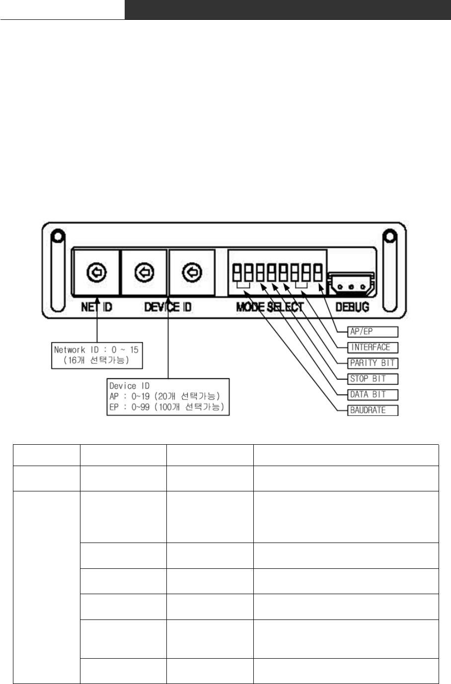
NET ID 0 ~ 15 Selection of Network(RF-band)
DEVICE ID 00 ~ 19(AP)
00 ~ 99(EP) Unique AP/EP ID in a network
MODE SELECT
Baudrate
00 : 4800bps
01 : 9600bps
10 : 19200bps
11 : 38400bps
Baud-Rate for communication with
End-Device.
Data Bit Length 0 : 7Bits
1 : 8Bits Length of Data Bit
Stop Bit Length 0 : 1Bit
1 : 2Bits Length of Stop Bit
Parity Bit 0 : Even
1 : None Use of Parity Bit
Interface
00 : RS232
01 : RS485
10 : RS422
Selection of interface
AP/EP Select 0 : EP
1 : AP Selection of RF-Modem Mode

RF Data Modem HWC-M100 / HWC-W100 / HWC-W120
16
∎ Frequency Table according to setting of NET-ID is as following:
NET ID Frequency NET ID Frequency
0 2,405 MHz 8 2,445 MHz
1 2,410 MHz 9 2,450 MHz
2 2,415 MHz 10 2,455 MHz
3 2,420 MHz 11 2,460 MHz
4 2,425 MHz 12 2,465 MHz
5 2,430 MHz 13 2,470 MHz
6 2,435 MHz 14 2,475 MHz
7 2,440 MHz 15 2,480 MHz
< Frequency Table for Network-ID >
∎ All device in a nework has the same NET-ID with the same frequency. It is good to
avoid the use of adjacent NET-ID in a adjacent area to enhance the stability of the
frequency
∎ The stability of a communication can be enhanced that it possibly excludes the
wireless LAN or Bluetooth, and the installation of the Zigbee equipment from the Network
neighboring in which it is installed by using the frequency of the ISM BAND.
∎ Basically, one RF-Master need to be installed in a network and can manage 1~20 APs
and 1~100 EPs at the same time. Number of AP that is installed, is related to the
coverage of each network and Number of EP is same as the number of End-Device that you
want to use in each network.
∎ You can use UP-Link connector to connect with RF-Master. And you can use DN-Link
connector to connect with next AP in which you can use UP-Link.
∎ You can use RS-422 port to connect with End-Device. Assignment of pin is different
according to the type of interface as following:
Pin Number Description
RS232 RS422 RS485
1 TXD+ TRXD+
2 TXD- TRXD-
3 RXD+
4 GND GND GND
5 GND GND GND
6 RXD-
7TXD
8RXD

RF Data Modem HWC-M100 / HWC-W100 / HWC-W120
17
∎ In AP-mode, you need to set Net-ID, Device-ID, AP/EP-Mode as follows:
- NET-ID : Network Number. Each network has its own unique frequency band.
and you can select one of the 16 network.(Net.ID : 0~15)
- DEVICE-ID : Device-ID of the AP. Each AP has its own unique number in a network.
and you can select one of the 20 APs.(Device-ID : 0~19)
- AP/EP-Mode : You must turn the dip-switch for AP/EP-mode to ON.
∎ In AP-Mode, RF-Modem communicate with RF-Master through Ethernet. Its network
parameter(IP-address, subnet-mask, gateway, MAC-address) is automatically configured by
Device-ID because it is operated in private network.
ex.1) In AP Mode, Device-ID is 3.
Device ID : 3
IP Address : 192.168.10.53(Device-ID + 50)
Subnet Mask : 255.255.255.0
Gateway : 192.168.10.254
MAC Address : 00:0A:1F:00:EC:35(Device-ID + 50)
ex.2) In EP Mode, Device ID is 3
Device ID : 3
IP Address : 192.168.10.103(Device ID + 100)
Subnet Mask : 255.255.255.0
Gateway : 192.168.10.254
MAC Address : 00:0A:1F:00:EC:67(Device ID + 100)
RF Data Modem HWC-M100 / HWC-W100 / HWC-W120
18
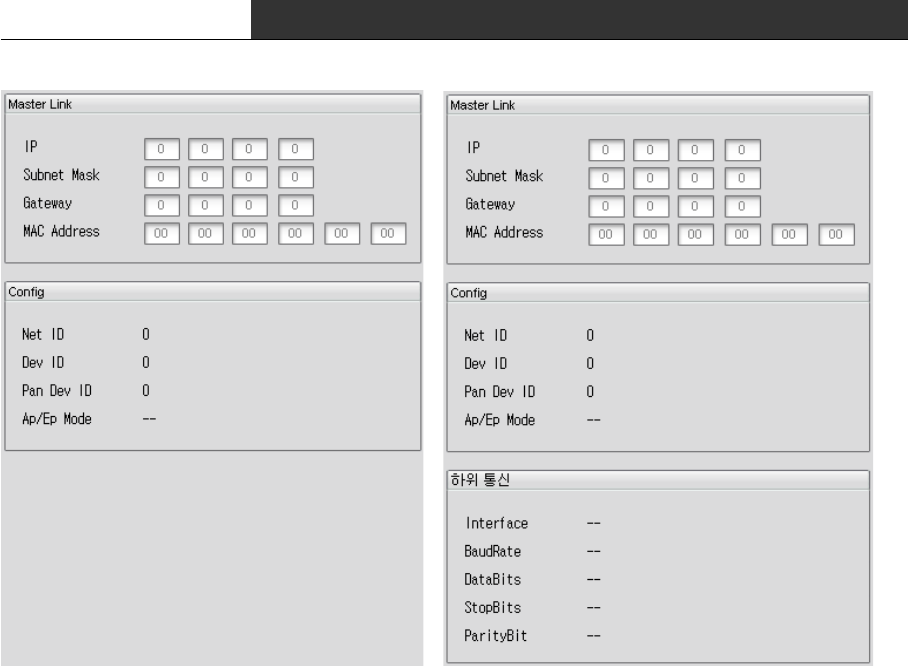
< AP Information Window in GUI > < EP Information Window in GUI >
RF Data Modem HWC-M100 / HWC-W100 / HWC-W120
19
2.4 Configure the Setting of RF-Modem(HWC-W120)
∎ You can configuration NET-ID, DEVICE ID, MODE by Rotary Swtich
- NET-ID : Network Number. Each network has its own unique frequency band.
and you can select one of the 16 network.(Net.ID : 0~15)
- DEVICE-ID : Each HWC-W120 has its own unique number in a network.(Device-ID : 0~19)
- MODE : You can select Rf Test MODE or Normal operation Mode(0~8 : Normal / 9 : Test)
∎ Frequency Table according to setting of NET-ID is as following:
NET ID Frequency NET ID Frequency
0 2,405 MHz 8 2,445 MHz
1 2,410 MHz 9 2,450 MHz
2 2,415 MHz 10 2,455 MHz
3 2,420 MHz 11 2,460 MHz
4 2,425 MHz 12 2,465 MHz
5 2,430 MHz 13 2,470 MHz
6 2,435 MHz 14 2,475 MHz
7 2,440 MHz 15 2,480 MHz
∎ All device in a nework has the same NET-ID with the same frequency. It is good to
avoid the use of adjacent NET-ID in a adjacent area to enhance the stability of the
frequency
∎ The stability of a communication can be enhanced that it possibly excludes the
wireless LAN or Bluetooth, and the installation of the Zigbee equipment from the Network
neighboring in which it is installed by using the frequency of the ISM BAND.
∎ Basically, one RF-Master need to be installed in a network and can manage 1~20 APs
and 1~100 EPs at the same time. Number of AP that is installed, is related to the

RF Data Modem HWC-M100 / HWC-W100 / HWC-W120
20
coverage of each network and Number of EP is same as the number of End-Device that you
want to use in each network.
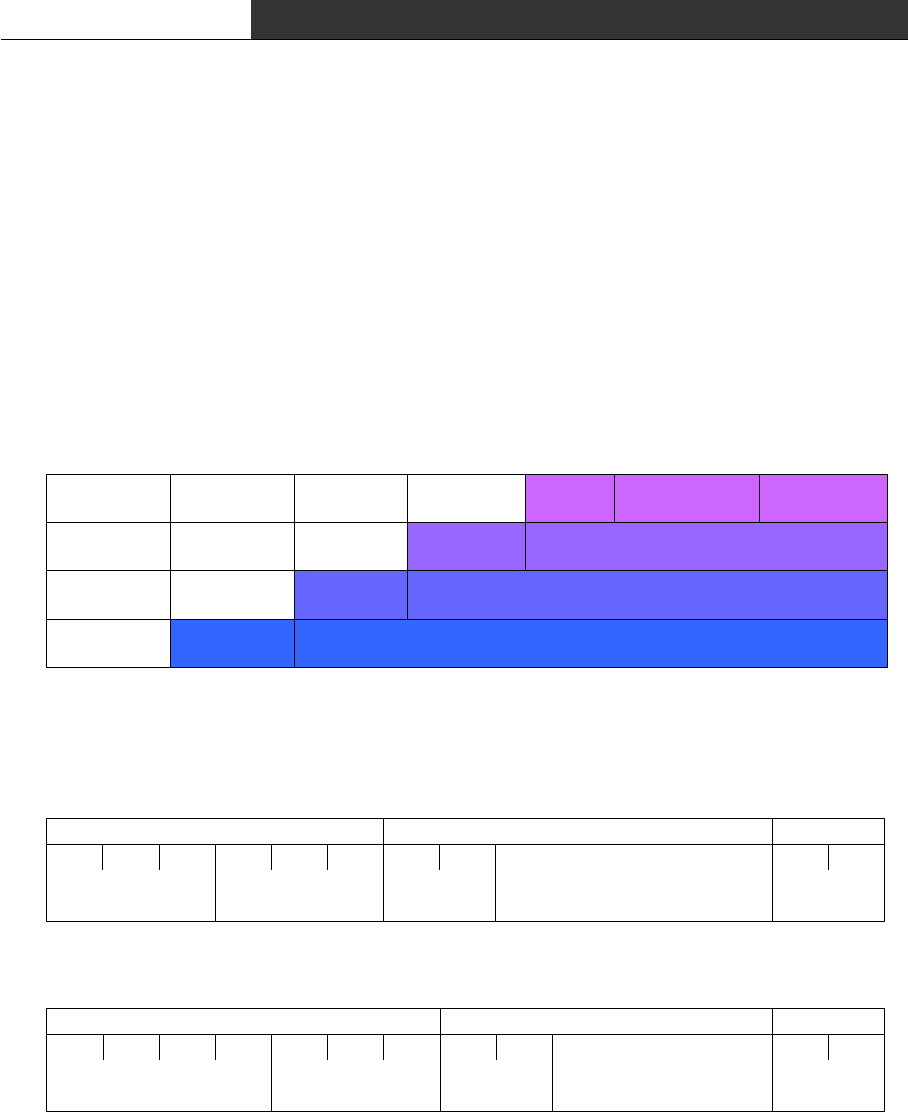
∎ You can use Serial port to connect with End-Device. Assignment of pin is differnet
according to the type of interface as following :
pin numberr RS-232 RS-485 or RS-422 RS-422
1TXD
2RXD
3GNDGNDGND
4 TRXD+ TXD+
5 TRXD- TXD-
6RXD+
7RXD-
RF Data Modem HWC-M100 / HWC-W100 / HWC-W120
21
3. Communication with HOST
3.1 Communication method
∎ You can use Up-Link connector of RF Master to communicate with HOST through ethernet.
HOST must know the IP address and udp port of RF Master. Udp port is fixed to 9506.
You can set-up the IP address of RF Master in the Host Link window of GUI.
3.2 Communication data
∎ Communication data in the Ethernet Protocol is as follows :
RAV Layer Header Information Terminator
UDP Layer UDP Header UDP Information
IP Layer IP Header IP Information
MAC Layer MAC Header MAC Information
∎ Data of the UDP Information consists of Header, Infomation and Terminator as follows:
HOST → RF Master
Header Information Terminator
R X T 2 4 0 No1 No2 CR LF
3Bytes 3Bytes 2Bytes nBytes 2Bytes
HOST ← RF Master
Header Information Terminator
@TXT240No1No2 CRLF
4Bytes 3Bytes 2Bytes nBytes 2Bytes
No.1~2 of the Information is Device-ID of the End Device.
It is same as Device-ID of EP. (possible range 00 to 99)

RF Data Modem HWC-M100 / HWC-W100 / HWC-W120
22
4. Communication with the End Device
4.1 Communication Method
∎ You can use Up-Link connector of RF-Modem to communicate with HOST through ethernet.
HOST must know the IP address and udp port of RF Master. Udp port is fixed to 9506.
You can set-up the IP address of RF Master in the Host Link window of GUI.
∎ You can use RS422 connector of RF-Modem which is in EP mode to communicate with End
Device. Communication method is selected by dip-switch for mode select. It could support
one of RS232, RS422 and RS485, and the assignment of pin is different according to
selection. You can also configure data bit, stop bit and parity bit to support the
End-device.
4.2 Communication Data
∎ Communication Data consists of header, informaiton and terminator as follows:
EP → End Device
Header Information Terminator
R X T 2 4 0 No1 No2 CR LF
3Bytes 3Bytes 2Bytes nBytes 2Bytes
EP ← End Device
Header Information Terminator
@TXT240No1No2 CRLF
4Bytes 3Bytes 2Bytes nBytes 2Bytes
No.1~2 of the Information is Device-ID of the End Device.
It is same as Device-ID of EP. (possible range 00 to 99)
RF Data Modem HWC-M100 / HWC-W100 / HWC-W120
23
5. Quick Start for GUI
5.1 Initial Screen after Execution
When you execute the GUI program, the following screen is shown up.
(In case of showing message about the setting of program, please refer to "5.11 Configure
the setting of communication with device"! )
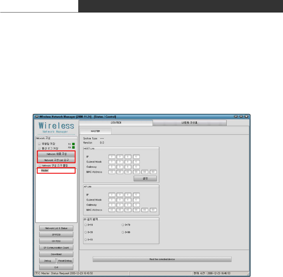
This system consists of Master, AP and EP. As soon as excutuion, you can only see Master
in left window. Therefore, user must request the list of device(AP, EP) by clicking
[Configure Network] or [Request Device List].
There is the following differences between [Configure Network] and [Request Device List].
∎ [Configure Network] : It send commands to Master to gather the list of AP/EP again,
Master begins to gather information and sends the progressing
status and result to GUI.
∎ [Request Device List] : It requests the device list that Master already gathers.
Master sends the device list of AP/EP to GUI.
Tip) After execution, It only show Master. If PC is not connected to Master, you couldn't
see any AP/EP in left window because PC can't receive the device list. In other words,
when PC is directly connected to AP/EP, PC can't receive any device list. In this case,

RF Data Modem HWC-M100 / HWC-W100 / HWC-W120
24
you can see AP.0/EP.0 by pressing 'F5'Key. It could be different with real device list,
and This is the function that you can see device information without Master.
RF Data Modem HWC-M100 / HWC-W100 / HWC-W120
25
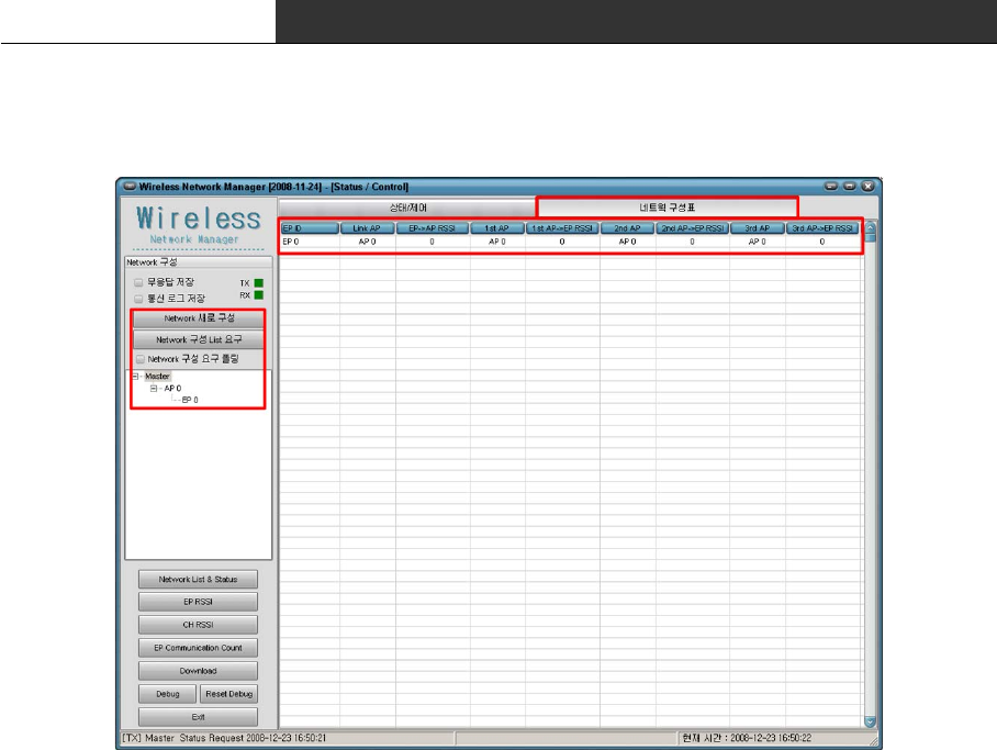
5.2 Network Configuration
User must request device list of network after execution of GUI.(Refer to "5.1 Initial
Screen after Execution"). The following is explanation about result of request.
At first, user must watch the left window. After requeset the network configuratin, It
shows Master, APs and EPs. The upper window shows one AP and one EP that communicate with
Master and owner-member relation between them.
Device list of the left window shows result of request briefly. You must click "Network
Configuration" to see more detail.
The following is in the network configuration.
∎ EP ID : EP's ID
∎ Link AP : AP linked to each EP
∎ EP → AP RSSI : Receiver-Sensitivity that measured in AP
∎ 1st, 2nd, 3rd AP : List of AP that selected by Receiver-Sensitivity
∎ 1st, 2nd, 3rd AP → EP RSSI : Receiver-Sensitivity that measured in EP
In the "Network Configuration", you can find out the linked AP list, its
receiver-sensitivity and list of adjacent APs.
RF Data Modem HWC-M100 / HWC-W100 / HWC-W120
26
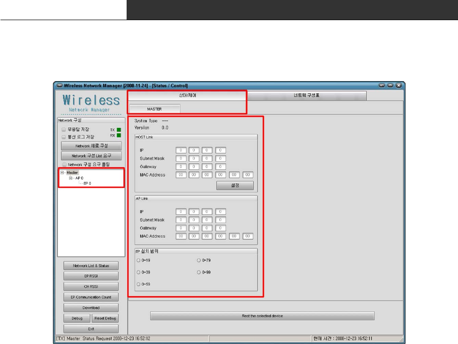
5.3 Status and Control of Master
In upper screen, please confirm whether the "state/control" is selected.
(If "status/control" is not selected, click the tab of "status/control")
The following is the status information of Master.
∎ System Type : Type of system.
∎ Version : Firmware version of Master
∎ Host Link : Network information to communicate with HOST.
These are network information of the Master.
∎ AP Link : Network information of communicate with AP.
(User do not need to set this information.)
∎ Range of EP : Number of EP that installed. (Only by range)
[Caution.1] When you want to see the status or control the value, "Network Polling" must
not be checked. GUI program requests the network device list when "Network Polling" is
checked and the status of selected device in other case, by periods.
[Caution.2] If you couldn't see the upper screen, please confirm whether you select
Master!
RF Data Modem HWC-M100 / HWC-W100 / HWC-W120
27
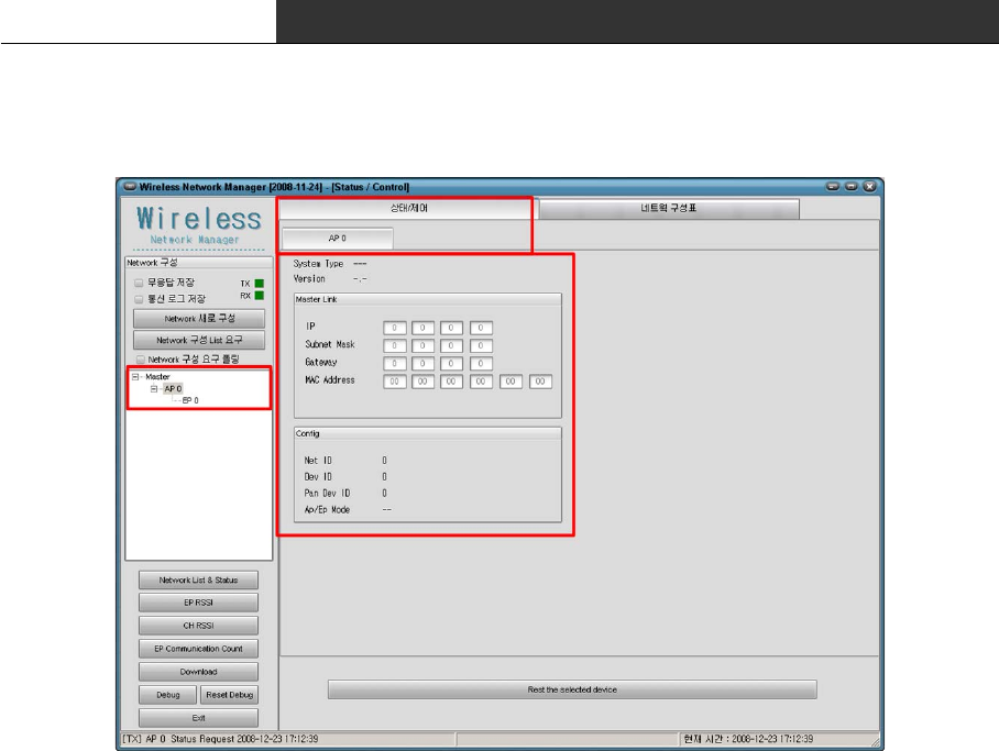
5.4 Status and control of AP
After selecting AP in device list, please confirm whether the "state/control" is selected
(If "status/control" is not selected, click the tab of "status/control")
The following is the status information of AP.
∎ System Type : Type of system.
∎ Version : Firmware version of AP.
∎ Master Link : Network information to communicate with Master.
(User do not need to set this information.)
∎ Config : Configuration information of AP
[Caution.1] When you want to see the status or control the value, "Network Polling" must
not be checked. GUI program requests the network device list when "Network Polling" is
checked and the status of selected device in other case, by periods.
[Caution.2] If you couldn't see the upper screen, please confirm whether you select AP!
RF Data Modem HWC-M100 / HWC-W100 / HWC-W120
28
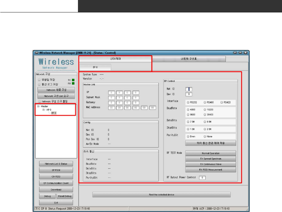
5.5 Status and Control of EP
After selecting EP in device list, please confirm whether the "state/control" is selected
(If "status/control" is not selected, click the tab of "status/control")
The following is the status information of EP.
∎ System Type : Type of system.
∎ Version : Firmware version of EP.
∎ Master Link : Network information to communicate with Master.
(User do not need to set this information.)
∎ Config : Configuration information of EP
∎ Comm. of End Device : Information of serial port to communicate with End-device
∎ EP Control : Item to control EP.
[Caution.1] When you want to see the status or control the value, "Network Polling" must
not be checked. GUI program requests the network device list when "Network Polling" is
checked and the status of selected device in other case, by periods.
[Caution.2] If you couldn't see the upper screen, please confirm whether you select EP!
RF Data Modem HWC-M100 / HWC-W100 / HWC-W120
29
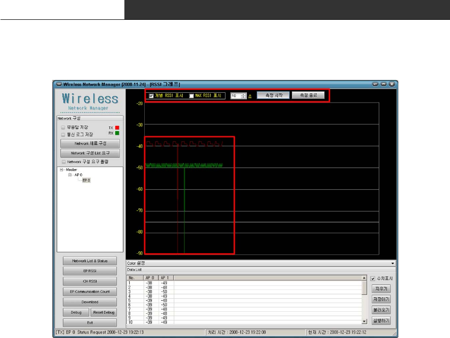
5.6 RSSI Graph
The Graph of RSSI visualizes the received signal strength between the installed AP and the
selected EP. When it tries to determine whether the installation position of APs is
appropriate or not, it will be useful.
The following is the usage :
1. Select the EP of the End-device that you want to see in left window.
2. Click the check box for "Individual RSSI" and "MAX RSSI"
Individual RSSI : display all of the RSSI value
MAX RSSI : display the maximum value of each RSSI valule
It is possible to select over 1 option.
3. Set the time. It can set till a maximum 200 second, and this time means the X-axis.
For example, If the time setting was 10 seconds, receiver-sensitivity data of 10 second
amount is drawn on a screen. The time itself to measure is not limited to 10 seconds.
Moreover, it is the setting about time interval to measure receiver-sensitivity data.
The time interval is calculated by following formula :
[Time interval for receiver-sensitivity data = time / 700]
4. Start to move the End-device and measure. (click "Start measure")
5. If the device does not communicate with any AP, finish to measure. and restart the
measurement after changing the installation position of AP.
(If the device does not communicate with any AP, it is not drawn on screen during that
time. In this case, you must confirm the installation position of AP! )
RF Data Modem HWC-M100 / HWC-W100 / HWC-W120
30
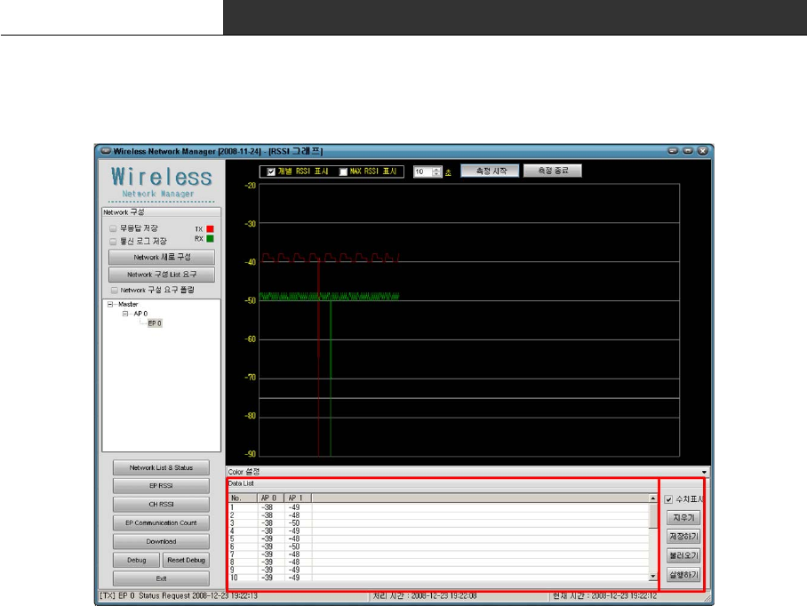
5.7 Store the RSSI Data
RSSI drawn on the graph is expressed in the list(Red box) as the numeric value.
This data can be stored as a file. And the stored file is retrieved and the RSSI graph can
be drawn again.
The following is for the button and the check box.
∎ Numeric : It sets up whether the numerical value display will be indicated or not.
∎ Delete : It deletes all contents of the table.
∎ Store : It stores the contents of the table as a CSV file that can be open in excel.
∎ Load : It load the stored data from a CSV file.
∎ Execute : It draw the RSSI graph with the loaded data.
RF Data Modem HWC-M100 / HWC-W100 / HWC-W120
31
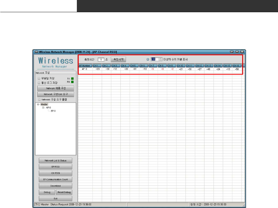
5.8 CH RSSI
The CH-RSSI is the RSSI value of the radio channel. It shows whether the channel is
already occupied or not. that is, function to search the available channel without the
cross talk.
The following is the usage:
1. Set up the measurement time. it sets up as a value between 1~10 second.
2. Set the option "Color value".
If the value is more than the set value, the value is expressed as the red letter. In
other case, It is expressed as the black letter. That is, user can easily confirm the
status of channel by its color.
3. Start to measure. (click "Start measure")
4. With the information of 16 channel, user confirm whether there is the channel in which
it is not occupied. And user determines whether there is the channel in which it can be
assigned to the current system or not.
RF Data Modem HWC-M100 / HWC-W100 / HWC-W120
32
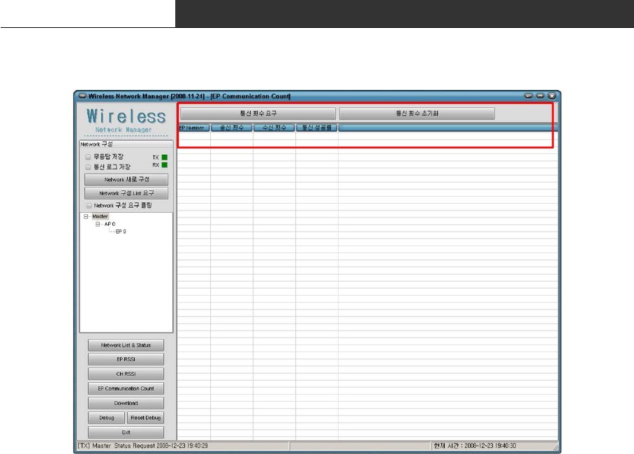
5.9 EP Communication Count
"EP Communication Count" is the function in which we know whether the communication state
with each EP is good or not.
The following is the usage:
∎ Request Status of Communication
: It require the number of transmission and reception
It shows the rate of communication success.
∎ Init Status of Communication
: It initialize all of values to '0'.
RF Data Modem HWC-M100 / HWC-W100 / HWC-W120
33
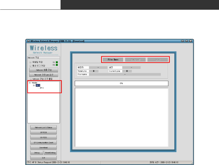
5.10 Download
This is the function that upgrade the firmware of the device
The following is the usage :
1. Select the device that is to be upgraded in the left list.
2. Click the 'File Open’button and show up the dialog box. Click the 'OK' button after
selecting the download file.
(The file extension is MAU[Master], AP[RFU] and EP[RFU]. If the file extension is
different, please confirm the device selected in left window)
3. If the file is opened correctly, 'Download' button is activated. Press the button to
begin to download.
4. Download in Progress. If you would like to finish the download, press the "Stop" button
5. Complete to download. If it fails, try again!
RF Data Modem HWC-M100 / HWC-W100 / HWC-W120
34
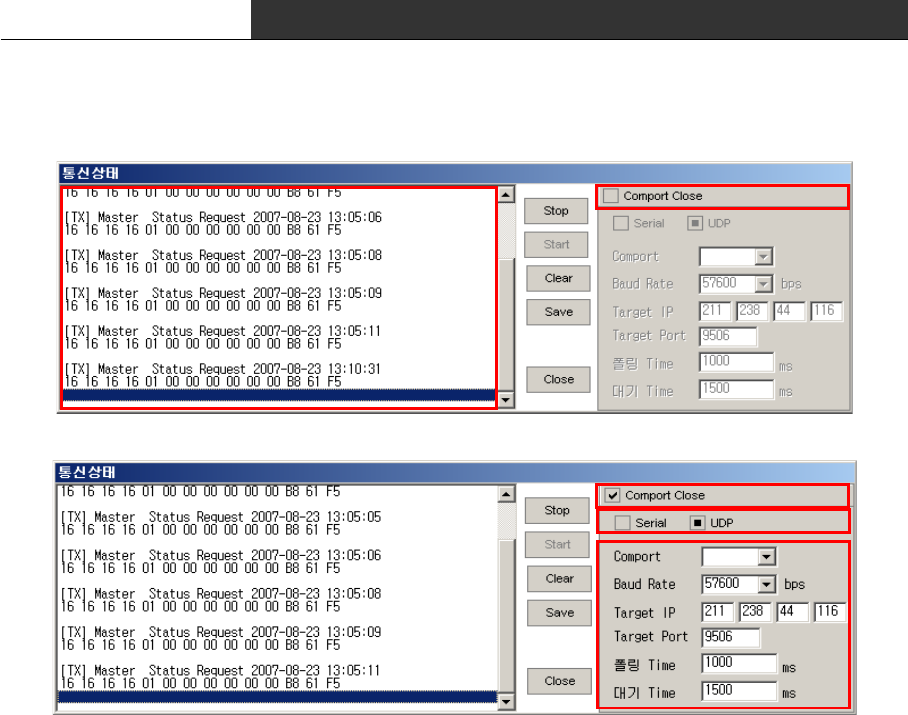
5.11 Configure the setting of communication with device
In spite of executing the program after connecting the device with PC, If it is not
communicated, The configuration of communication has to be confirmed.
The following is the usage :
1. Click the 'Debug' button in the main window.
2. Check whether the received data "[RX] -------" is in the left window.
You can use the 'start/stop' to start/stop the communication with the device.
If there is not the received data "[RX] -----", please confirm the hardware connection.
3. After checking the check box "Comport Close", you can change the configuration of
communication.
4. At first, confirm whether the PC is connected with the device through the serial cable
or LAN cable. And select one of Serial/UDP.
5. In case of serial, you must select and confirm the comport and baud-rate.
In case of UDP, you must confirm the Target IP and Target Port. Target IP means the IP
address of the device. Target Port must be always set to '9506'.
The initial value of the polling Time is 1000, and the initial value of the waite time
is 1500. It is recommended that is not changed.
6. After the setting the communication configuration, Be sure to uncheck the check box
'Comport Close' and confirm the received data "[RX] -----" in the left side of the window.
If there is not the received data, confirm whether the 'start' button is activated.

RF Data Modem HWC-M100 / HWC-W100 / HWC-W120
35
When there is an error related to the setting of communication after executing the GUI
program, the communication status window is automatically pop up. In this case, please
confirm the communication configuration again!
The error is in following case :
∎ In serial mode, when the comport is set up incorrectly.
∎ In UDP mode, when the TargetIP is set to "0.0.0.0" or the Target Port is set to '0'.
5.12 Others
The following is essential function to debug the system ; "No Response Store", "Store
Communication Log" and "Reset Debug". Normally "No Response Store", "Store Communication
Log" are unchecked.
RF Data Modem HWC-M100 / HWC-W100 / HWC-W120
36
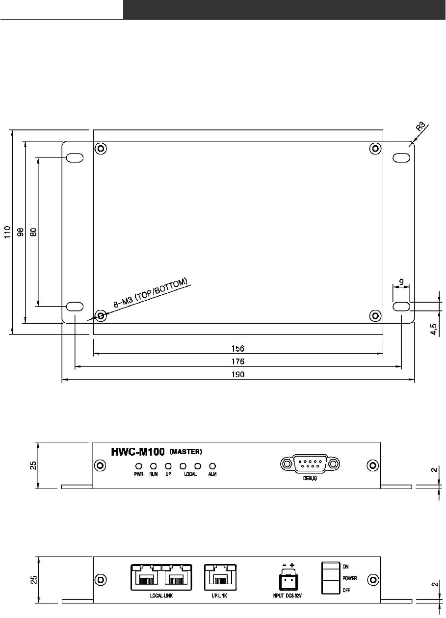
6. Dimension
6.1 RF Master(HWC-M100)
∎ TOP VIEW
∎ FRONT VIEW
∎ REAR VIEW
RF Data Modem HWC-M100 / HWC-W100 / HWC-W120
37
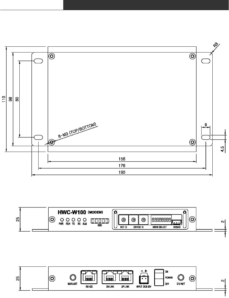
6.2 RF Modem(HWC-W100)
∎ TOP VIEW
∎ FRONT VIEW
∎ REAR VIEW
RF Data Modem HWC-M100 / HWC-W100 / HWC-W120
38
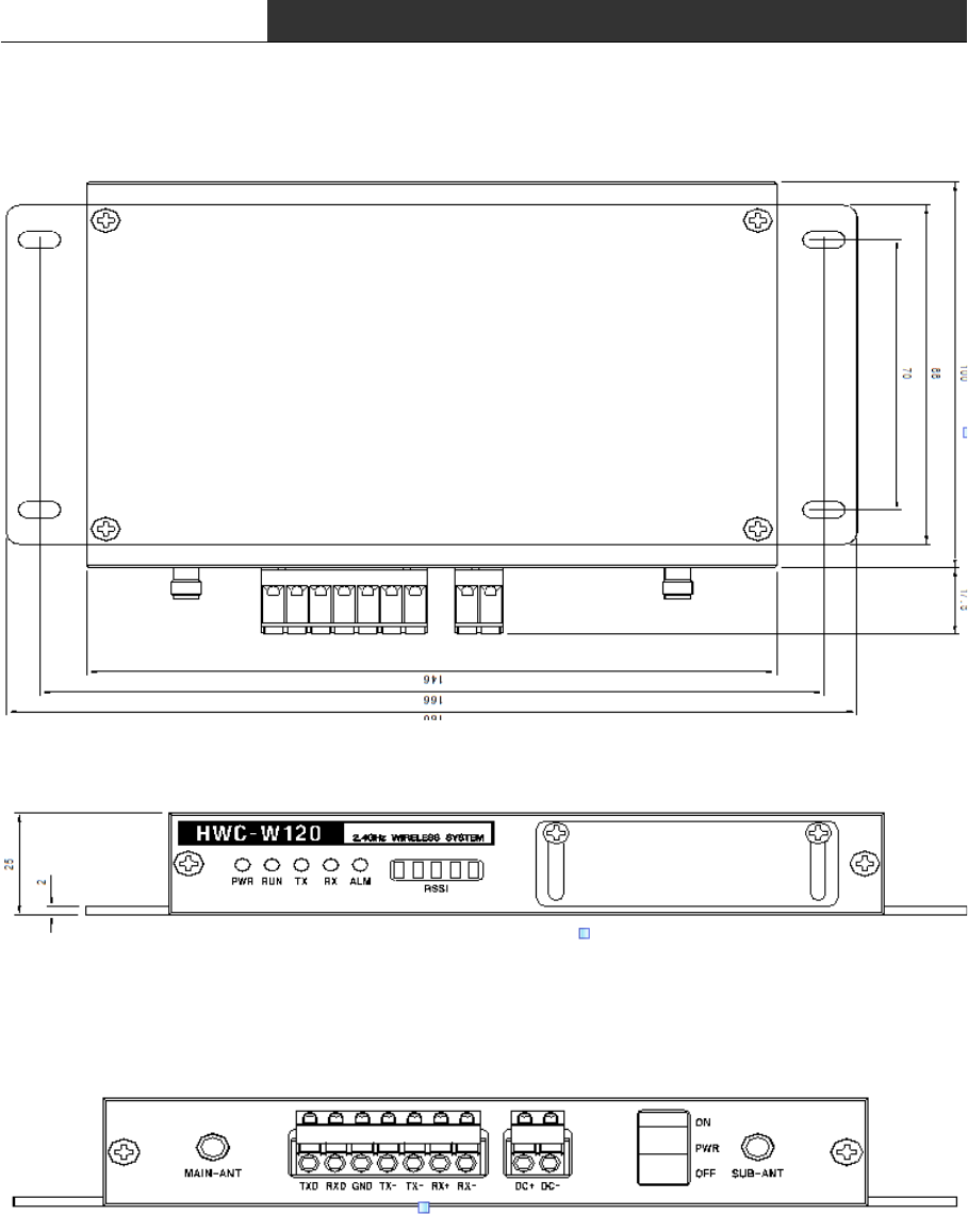
6.3 RF Modem(HWC-W120)
∎ TOP VIEW
∎ FRONT VIEW
∎ REAR VIEW

RF Data Modem HWC-M100 / HWC-W100 / HWC-W120
39
[ A/S CENTER ]
806 Ace Techno Tower 1st. 197-17 Guro3-Dong, Guro-Gu, Seoul, Korea
Tel. +82-2-3281-9300
Fax. +82-2-3281-7775
FCCInformationtoUser
ThisequipmenthasbeentestedandfoundtocomplywiththelimitsforaClassBdigital
device, pursuant to Part 15 of the FCC Rules. These limits are designed to provide
reasonable protection against harmful interference in a residential installation. This
equipmentgenerates,usesandcanradiateradiofrequencyenergyand,ifnotinstalledand
used in accordance with the instructions, may cause harmful interference to radio
communications. However, there is no guarantee that interference will not occur in a
particular installation.Ifthis equipmentdoes causeharmful interferencetoradio or
televisionreception,whichcanbedeterminedbyturningtheequipmentoffandon,the
userisencouragedtotrytocorrecttheinterferencebyoneofthefollowingmeasures:
•Reorientorrelocatethereceivingantenna.
•Increasetheseparationbetweentheequipmentandreceiver.
• Connect the equipment into an outlet on a circuit different fromthat towhichthe
receiveriscon-nected.
•Consultthedealeroranexperiencedradio/TVtechnicianforhelp.
Caution
Modificationsnotexpresslyapprovedbythepartyresponsibleforcompliancecouldvoid
theuser’sauthoritytooperatetheequipment.
FCC Compliance Information : This device complies with Part 15 of the FCC Rules.
Operation is subject to the following two conditions: (1) This device may not cause
harmfulinterference,and(2)thisdevicemustacceptanyinterferencereceived,including
interferencethatmaycauseundesiredoperation

40
WARRANTY
Warranty is to cover the operating defaults after the purchase
during the warranty period.(12 months after the purchase).
Please notify us the defaults for repairs with short description
of the defaults confirming the information of person in charge.
The demages(defaults) prescribed below are NOT to be covered by
warranty.
* Users faults by lack of care.
* Unauthorised electric currency connection defaults.
* Faults by the users own intention of dismantle or repairs.
* Demages caused by natural disaster. ( Fire, Flood, Earthquake,
Lighting, etc.)
* Replacement to new parts.
Shape or circuit of the product are subject to change without any
notice to improve the quality of product.
Customer Name :
Address :
Telephone Number :
E-Mail Address :
Serial # :
Date of Purchase :
Company purchased from :