Haier Telecom U802T CDMA 1X RTT (800MHz Single Band USB Modem) User Manual
Haier Telecom (Qingdao) Co., Ltd. CDMA 1X RTT (800MHz Single Band USB Modem)
UserManual.wiki
>
Haier Telecom
>
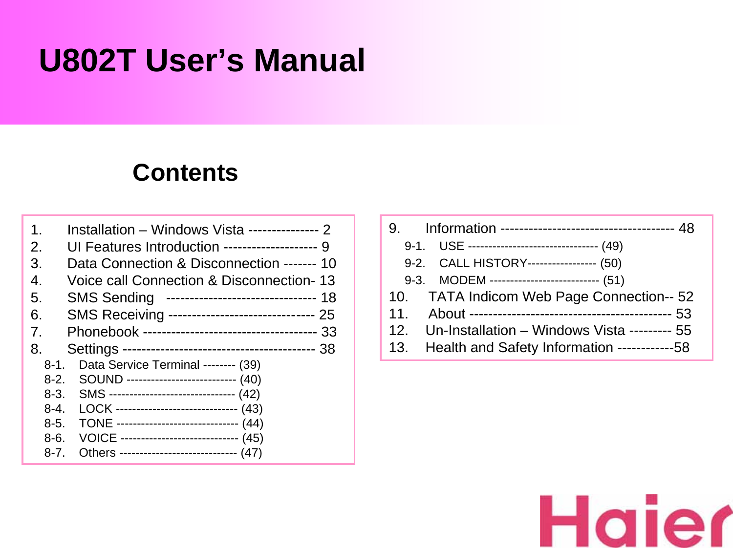
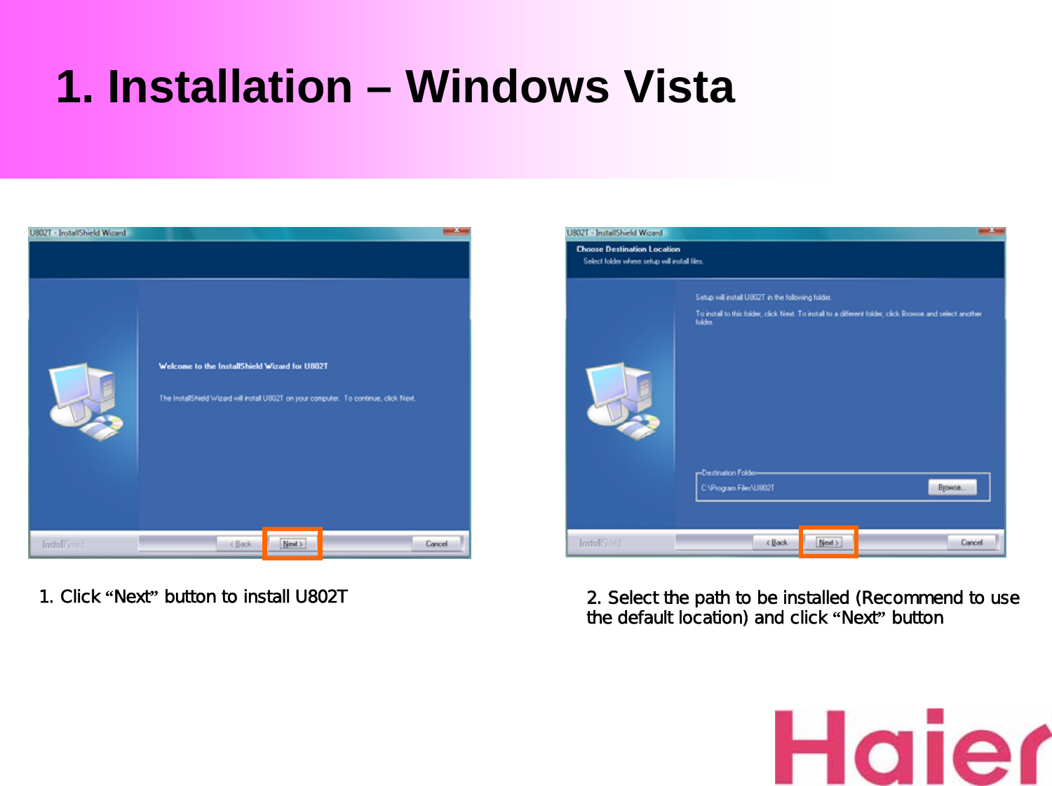
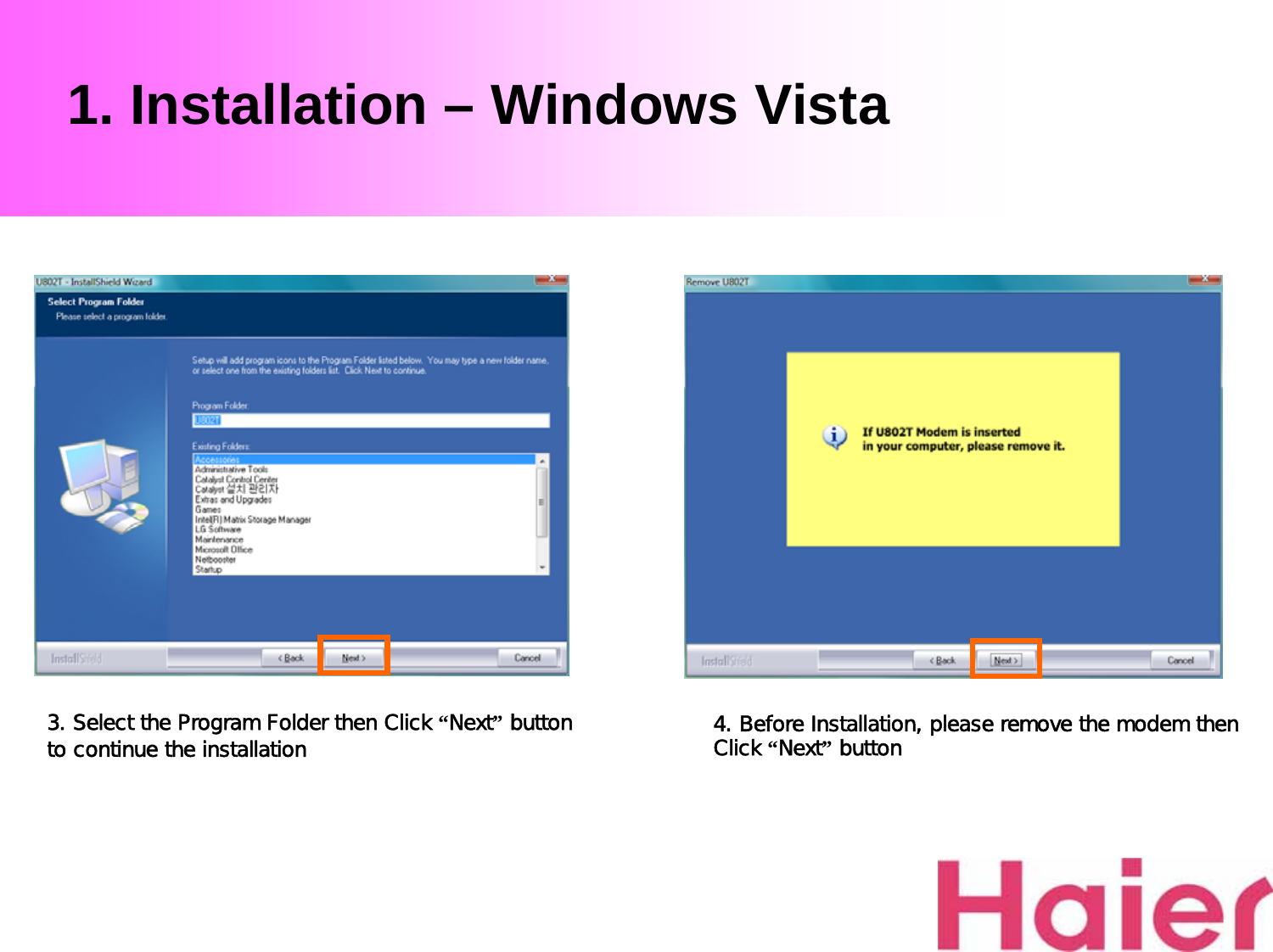
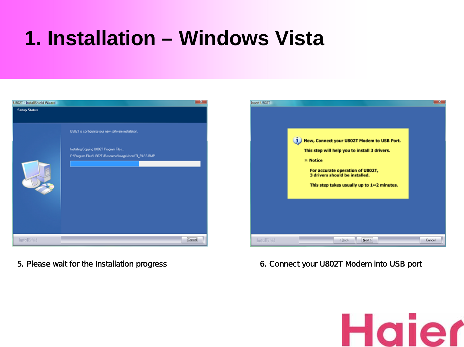
U802T User Manual
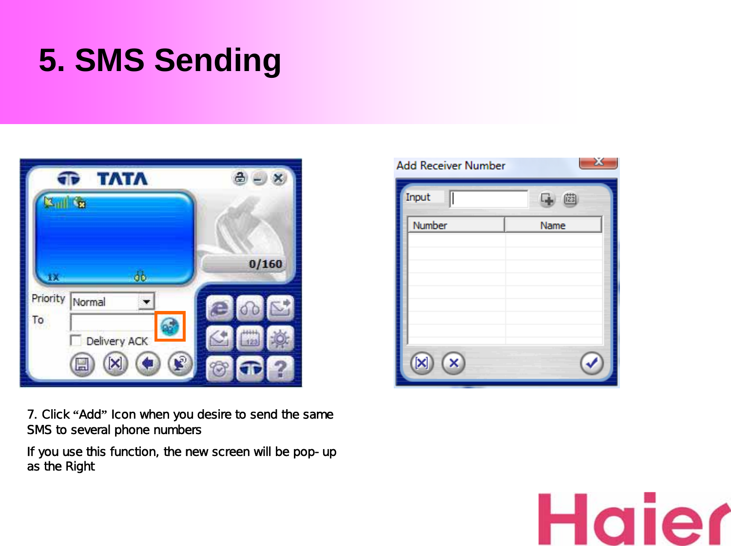
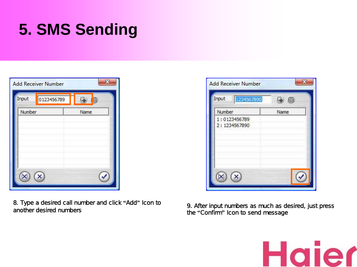
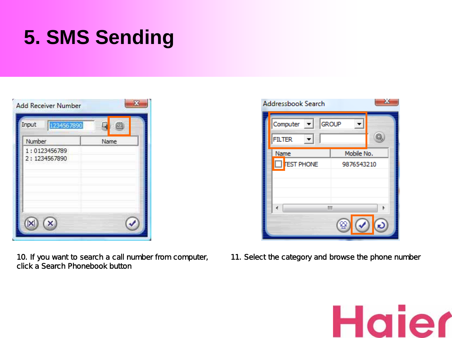
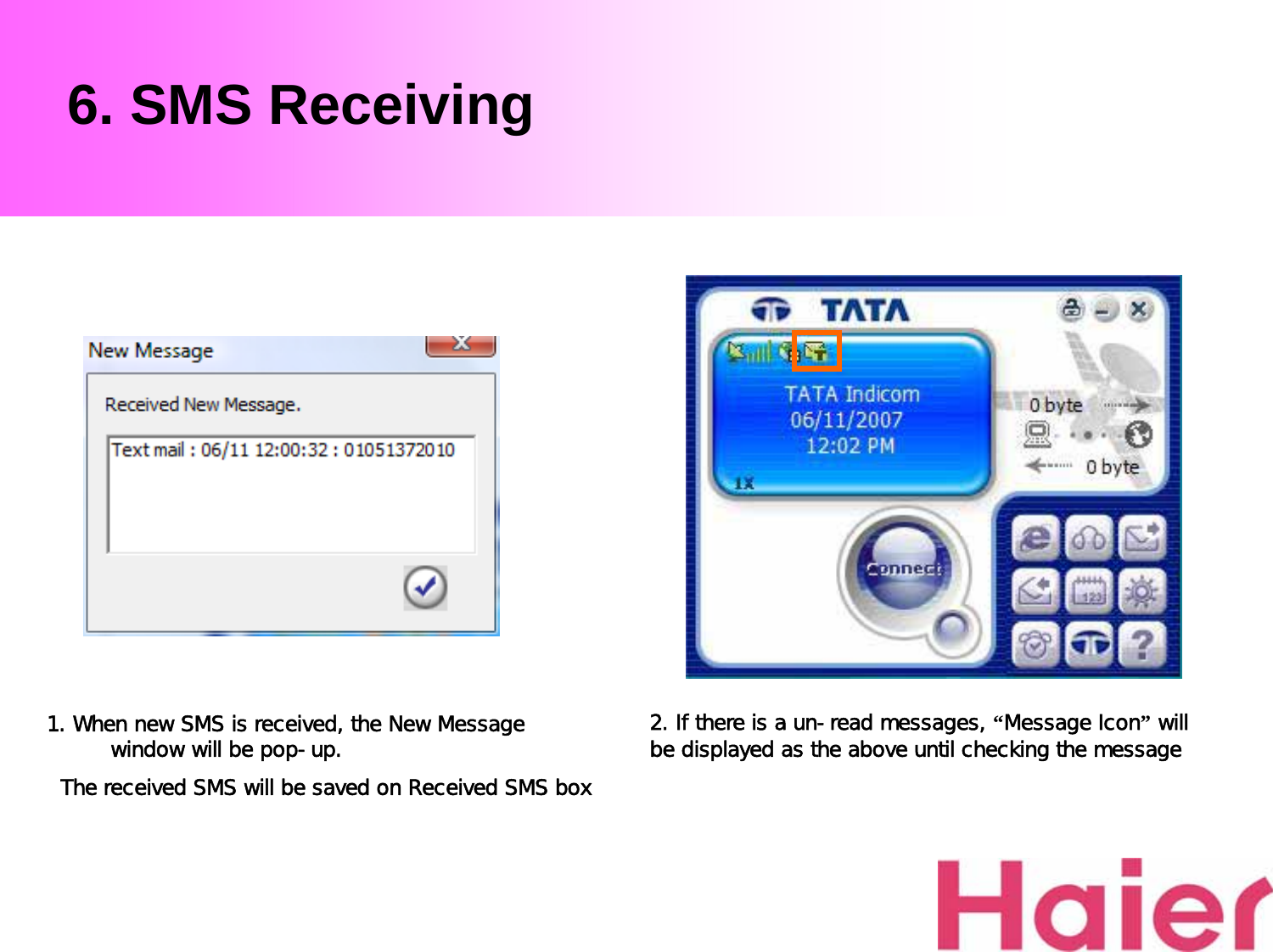
Users Manual
Navigation menu
Upload a User Manual
Namespaces
Wiki Guide
HTML
PDF
Info
Views
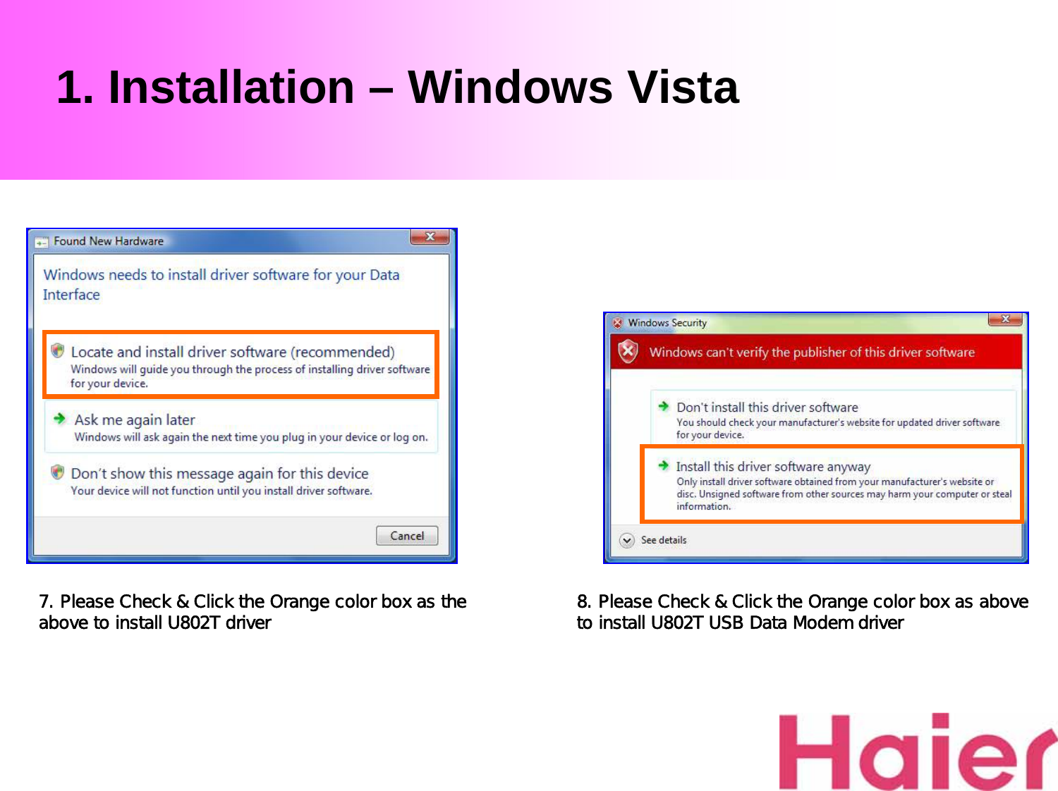
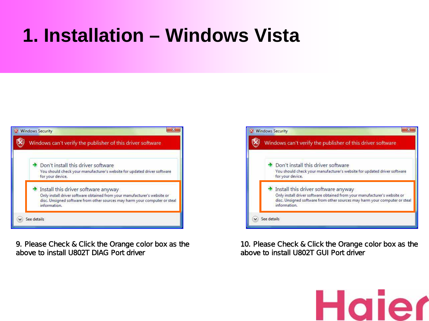
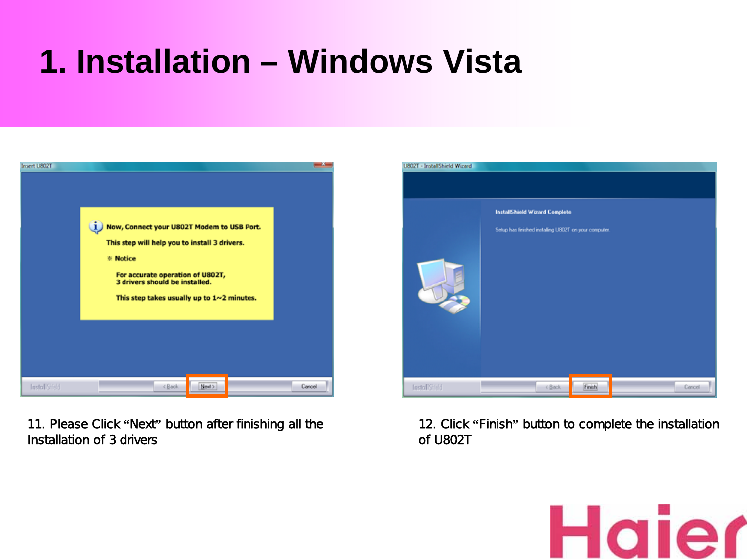
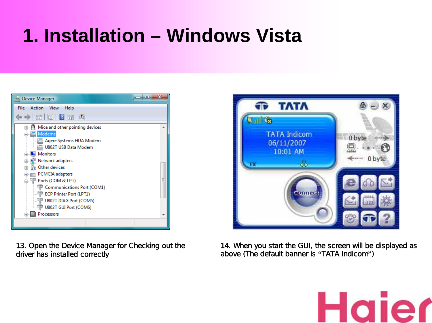
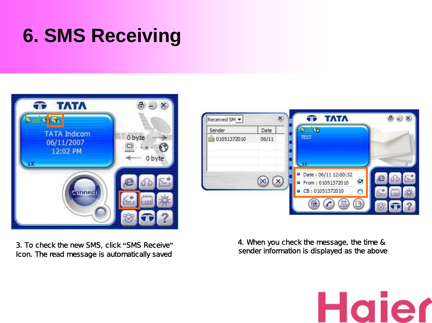
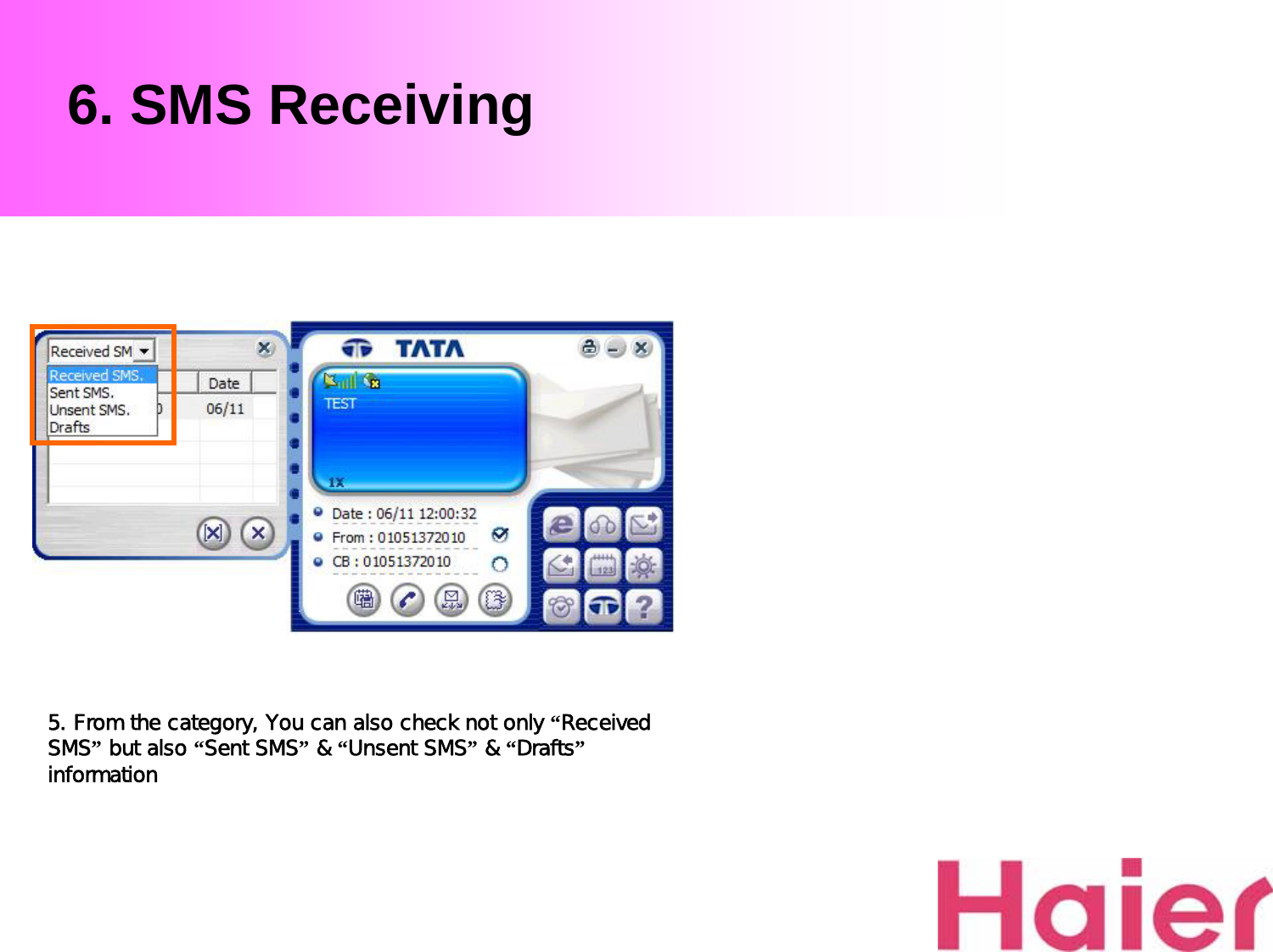
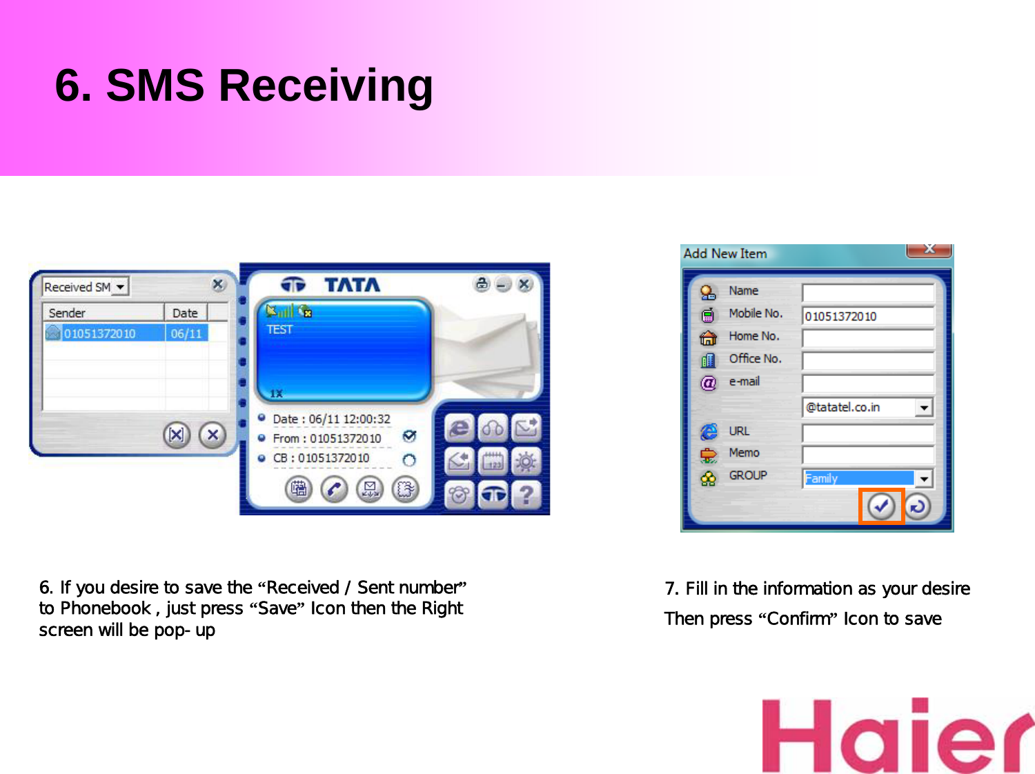
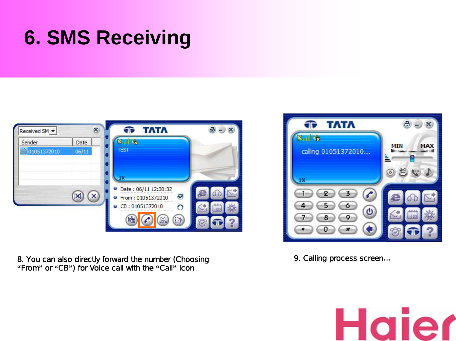
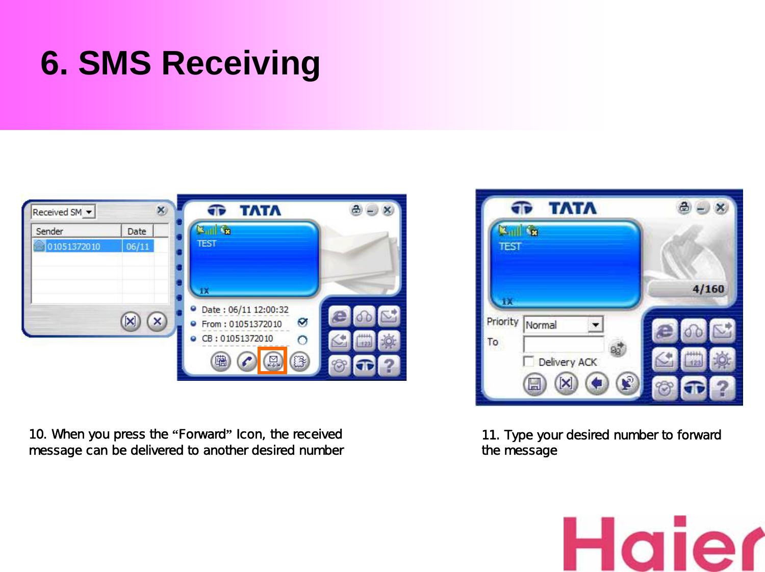
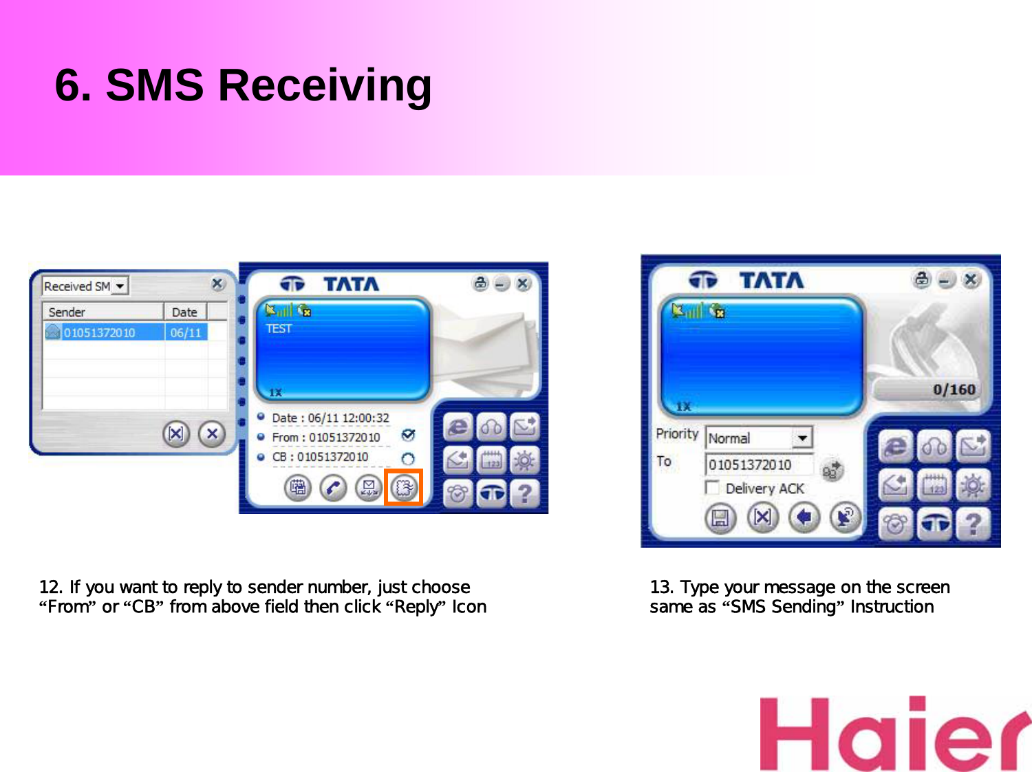
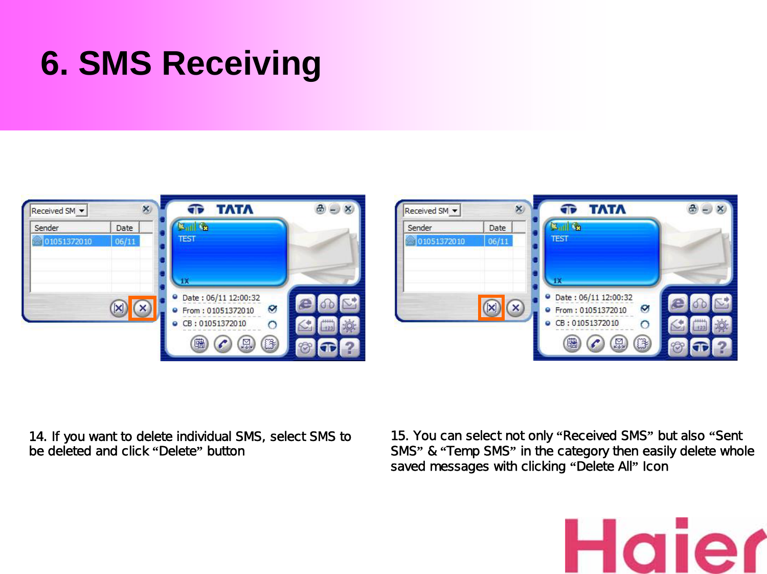
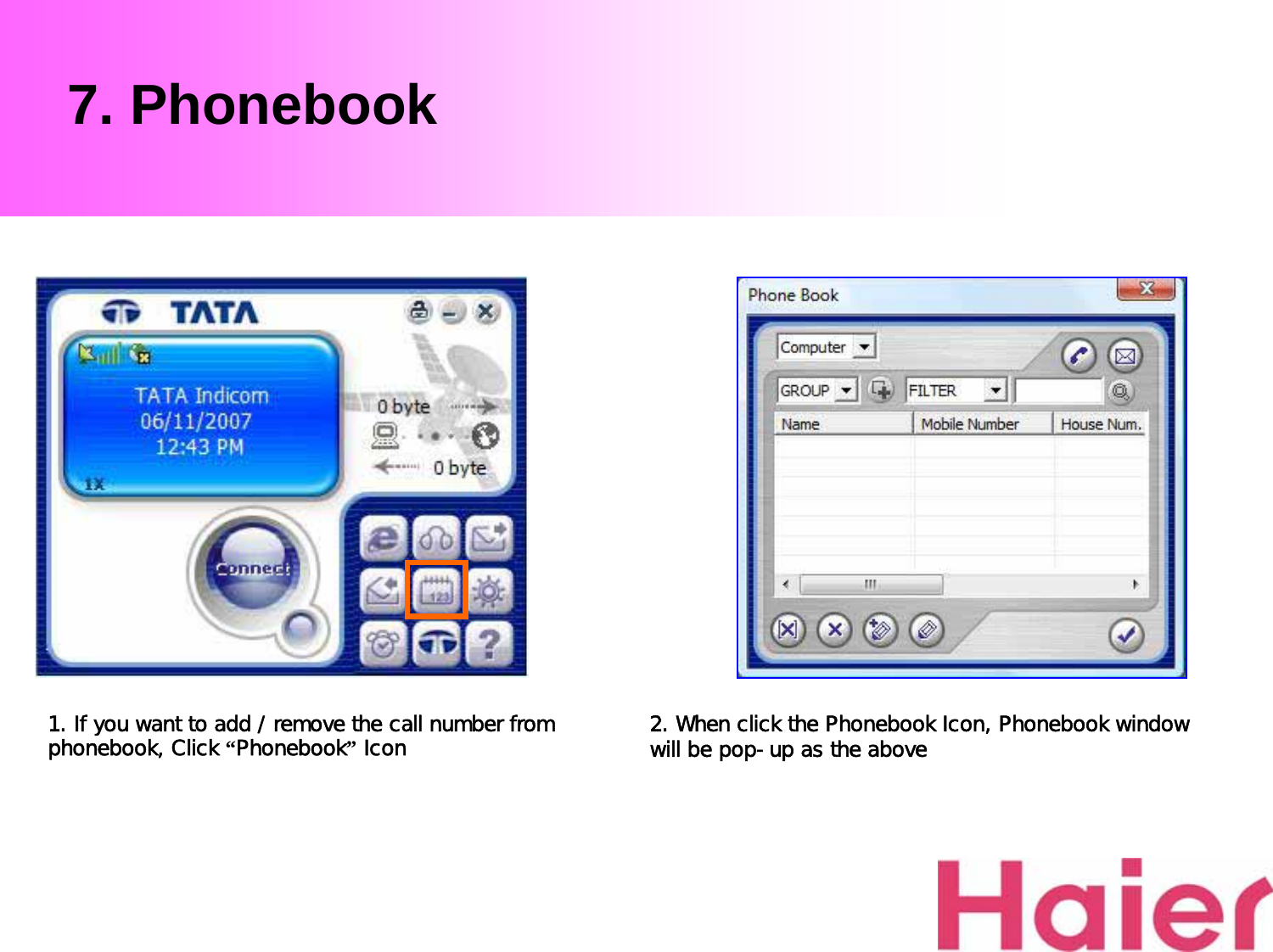
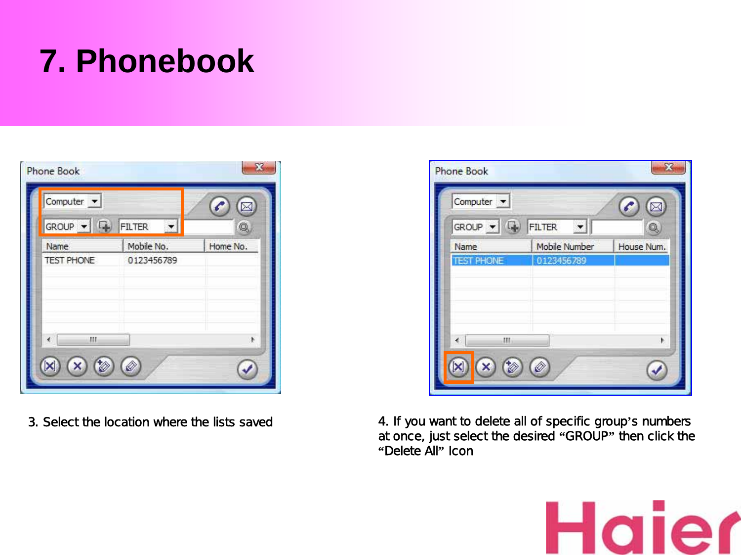
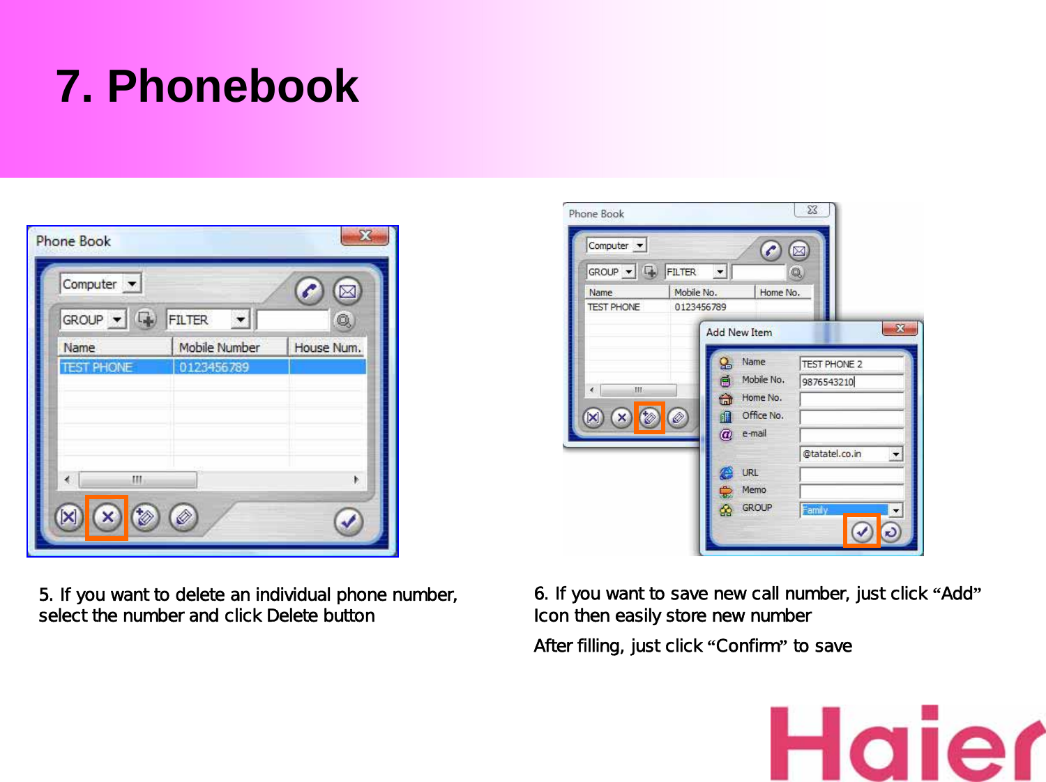
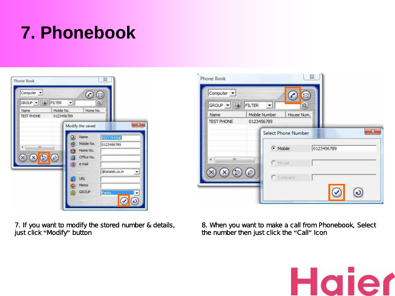
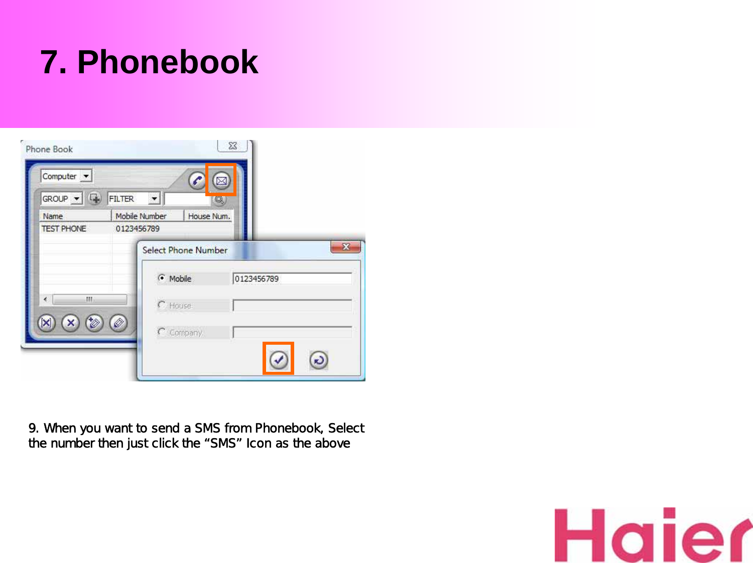
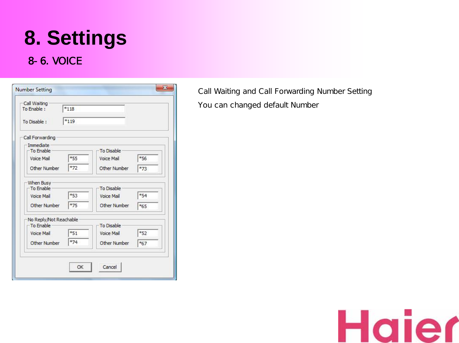
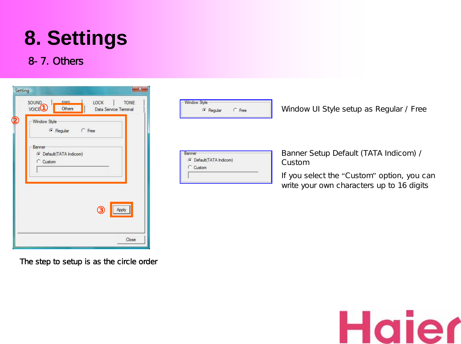
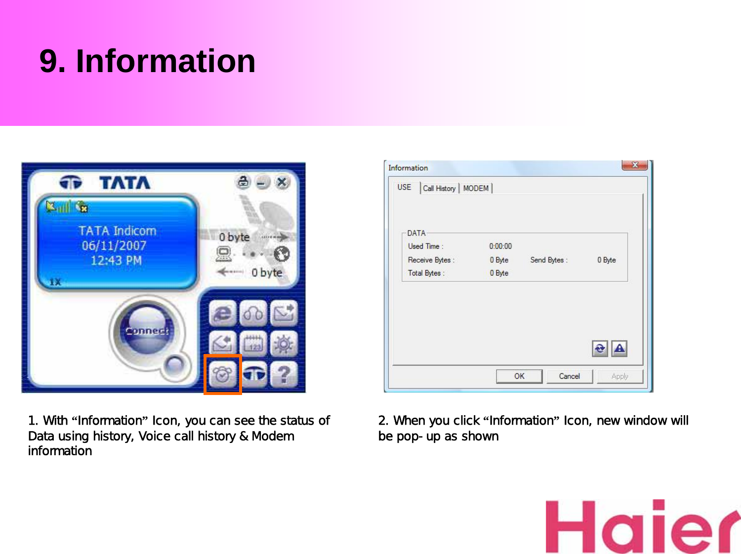
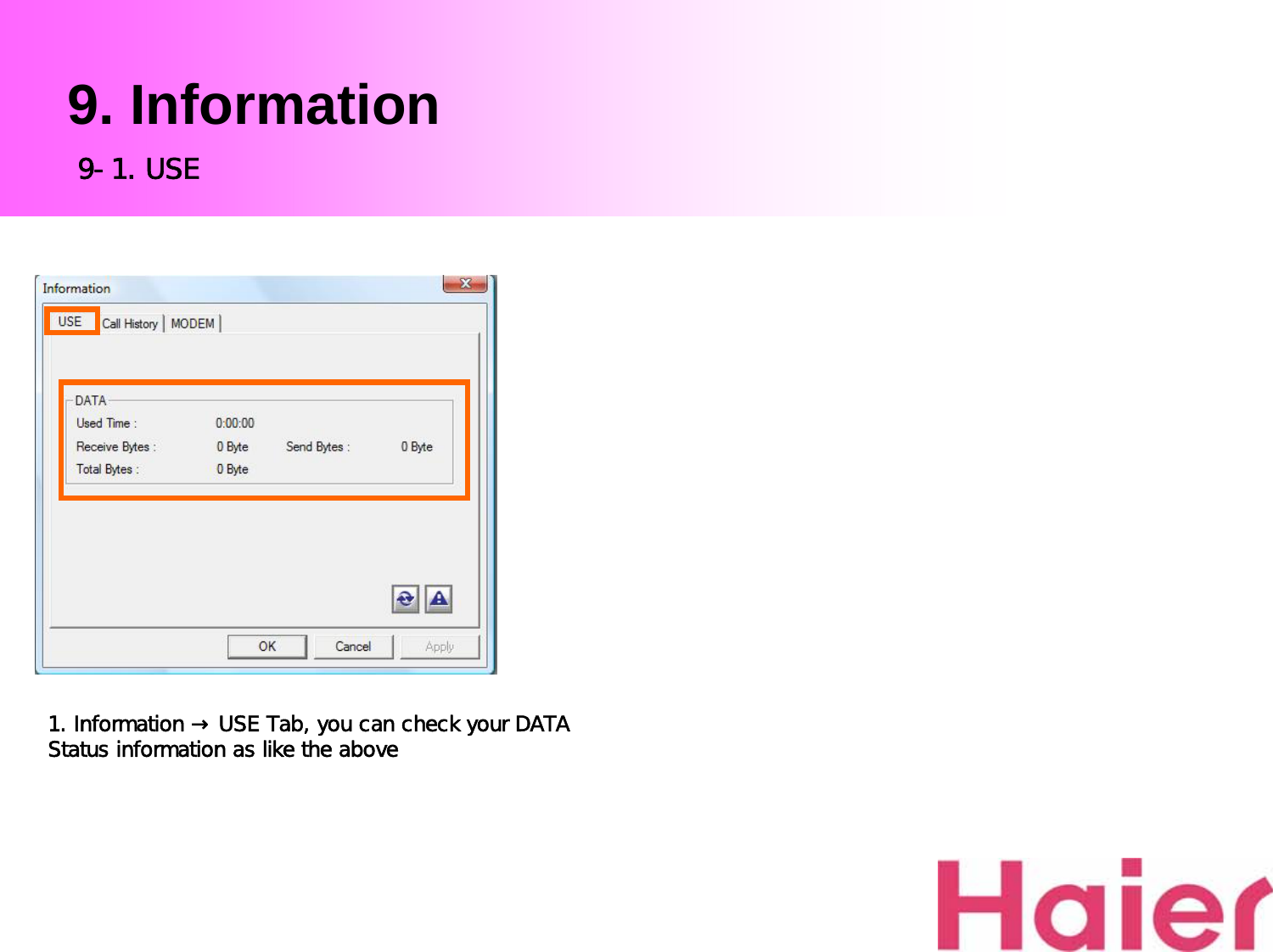
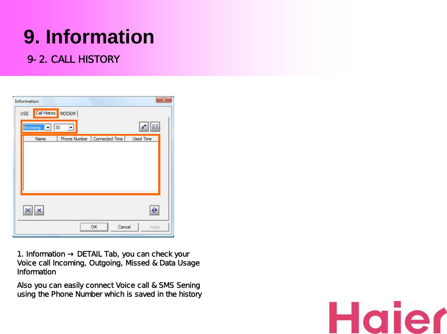
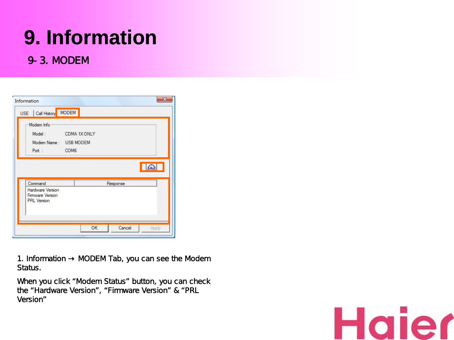
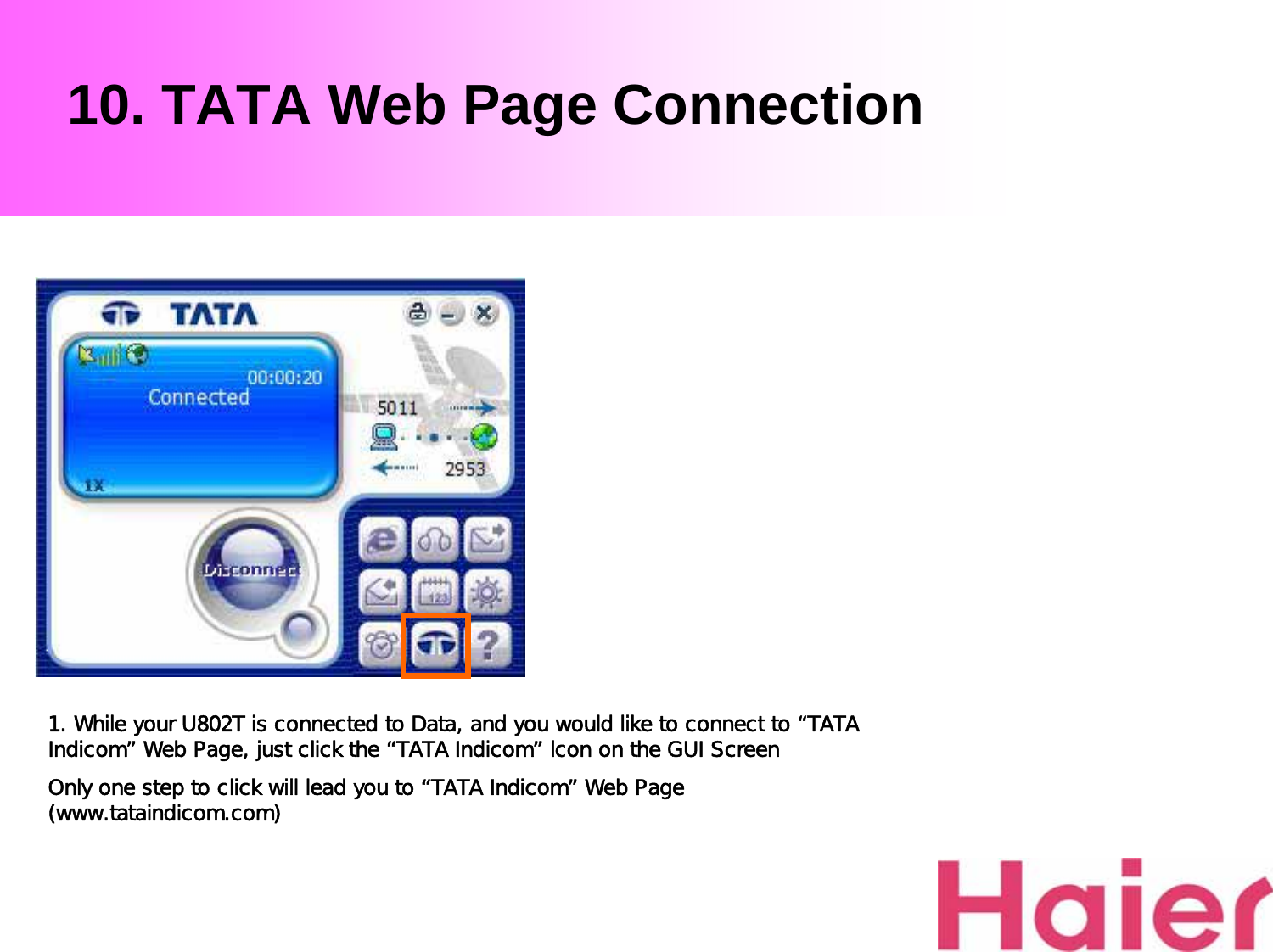
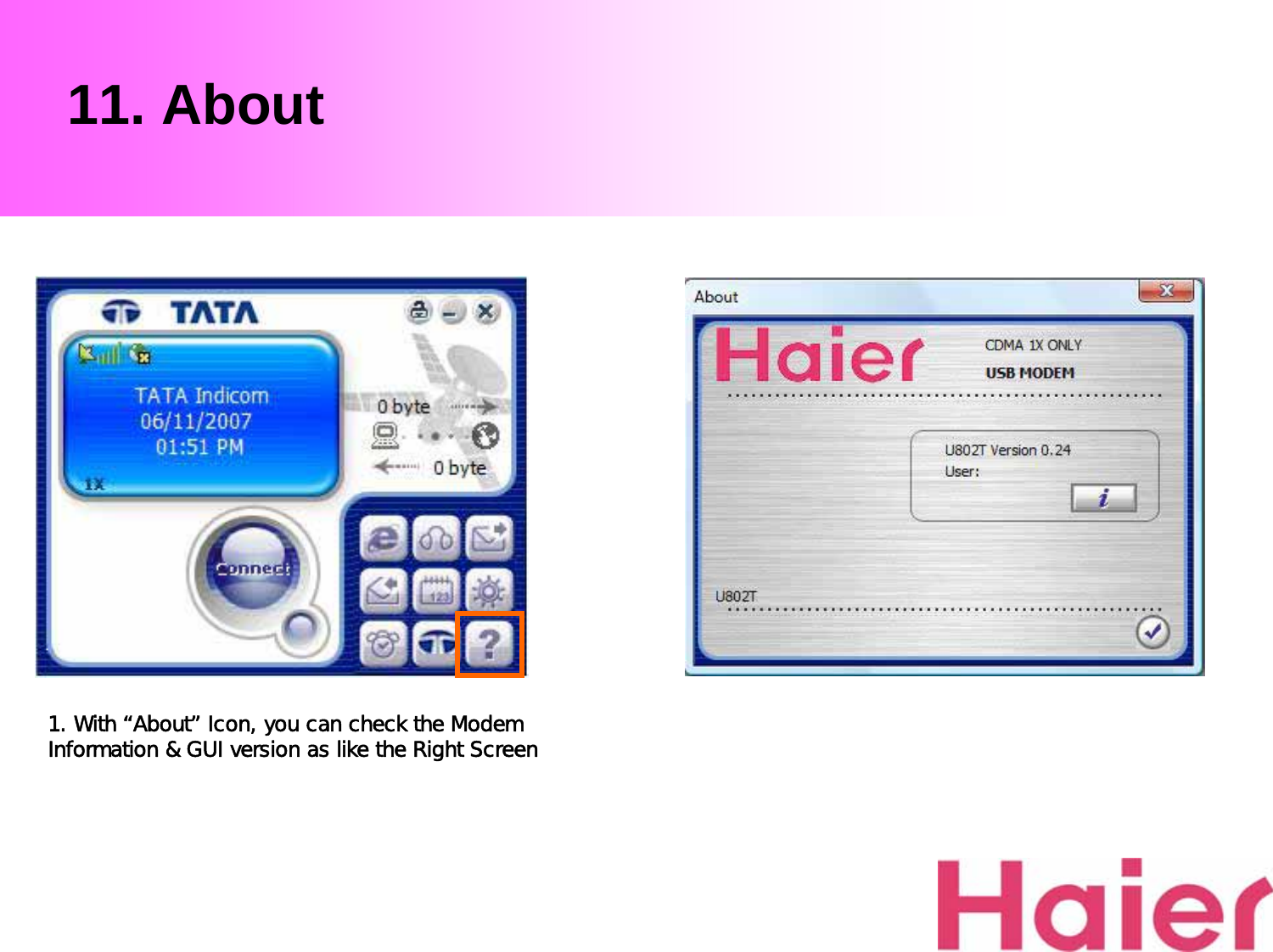
User Manual
Discussion / Help
Navigation