Haier Telecom U802T CDMA 1X RTT (800MHz Single Band USB Modem) User Manual
Haier Telecom (Qingdao) Co., Ltd. CDMA 1X RTT (800MHz Single Band USB Modem)
Users Manual

U802T User’s Manual
1. Installation – Windows Vista --------------- 2
2. UI Features Introduction -------------------- 9
3. Data Connection & Disconnection ------- 10
4. Voice call Connection & Disconnection- 13
5. SMS Sending -------------------------------- 18
6. SMS Receiving ------------------------------- 25
7. Phonebook ------------------------------------- 33
8. Settings ----------------------------------------- 38
8-1. Data Service Terminal -------- (39)
8-2. SOUND --------------------------- (40)
8-3. SMS ------------------------------- (42)
8-4. LOCK ------------------------------ (43)
8-5. TONE ------------------------------ (44)
8-6. VOICE ----------------------------- (45)
8-7. Others ----------------------------- (47)
9. Information ------------------------------------- 48
9-1. USE -------------------------------- (49)
9-2. CALL HISTORY----------------- (50)
9-3. MODEM --------------------------- (51)
10. TATA Indicom Web Page Connection-- 52
11. About ------------------------------------------- 53
12. Un-Installation – Windows Vista --------- 55
13. Health and Safety Information ------------58
Contents
1. Installation – Windows Vista
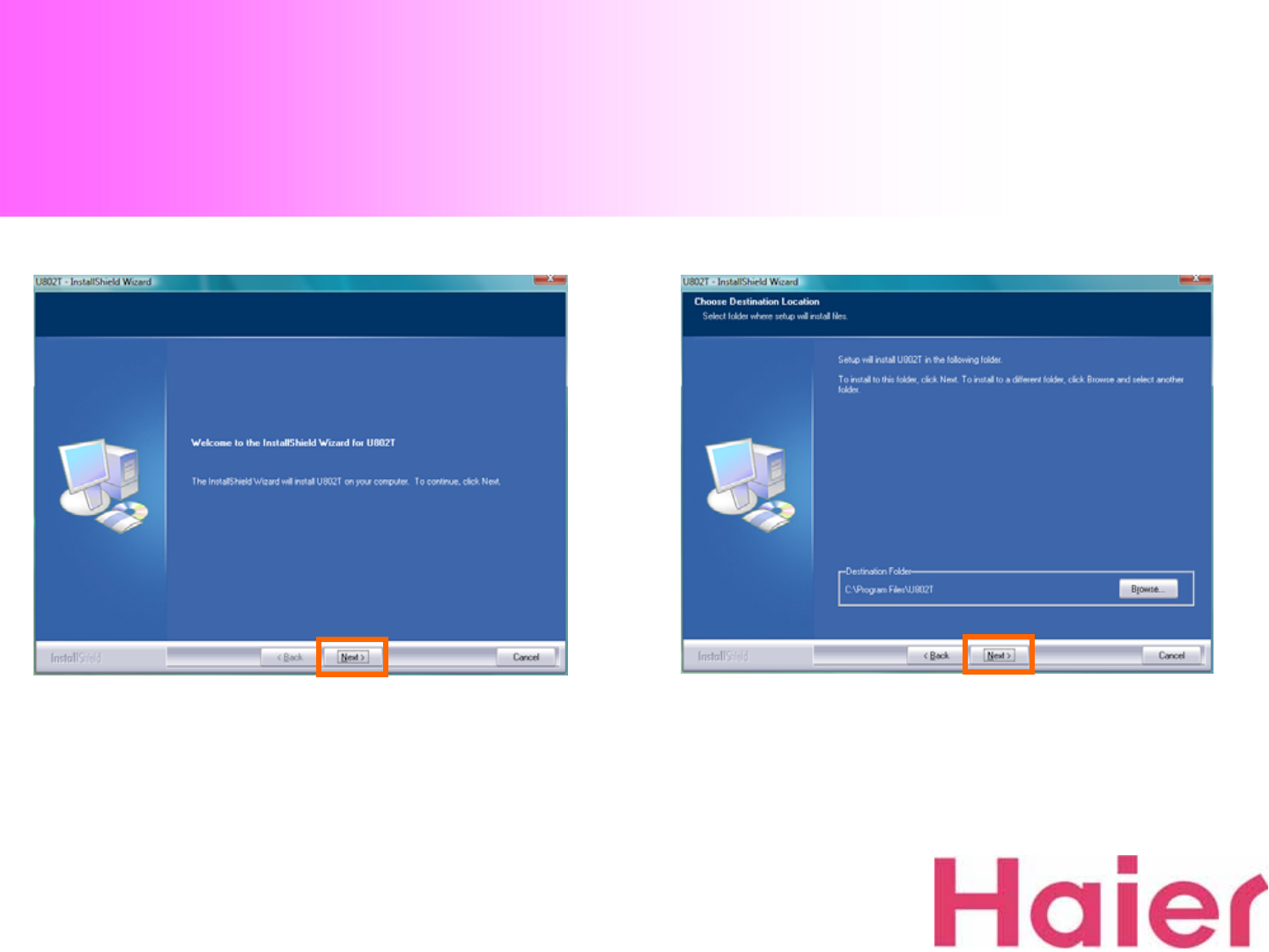
1. Click “Next”button to install U802T 2. Select the path to be installed (Recommend to use
the default location) and click “Next”button
1. Installation – Windows Vista
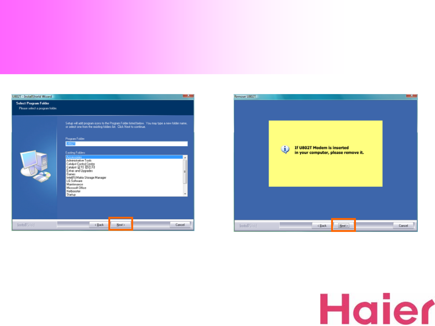
3. Select the Program Folder then Click “Next”button
to continue the installation 4. Before Installation, please remove the modem then
Click “Next”button
1. Installation – Windows Vista
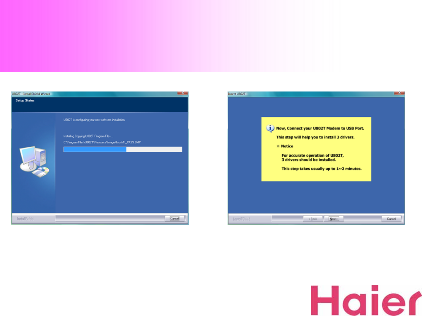
5. Please wait for the Installation progress 6. Connect your U802T Modem into USB port
1. Installation – Windows Vista
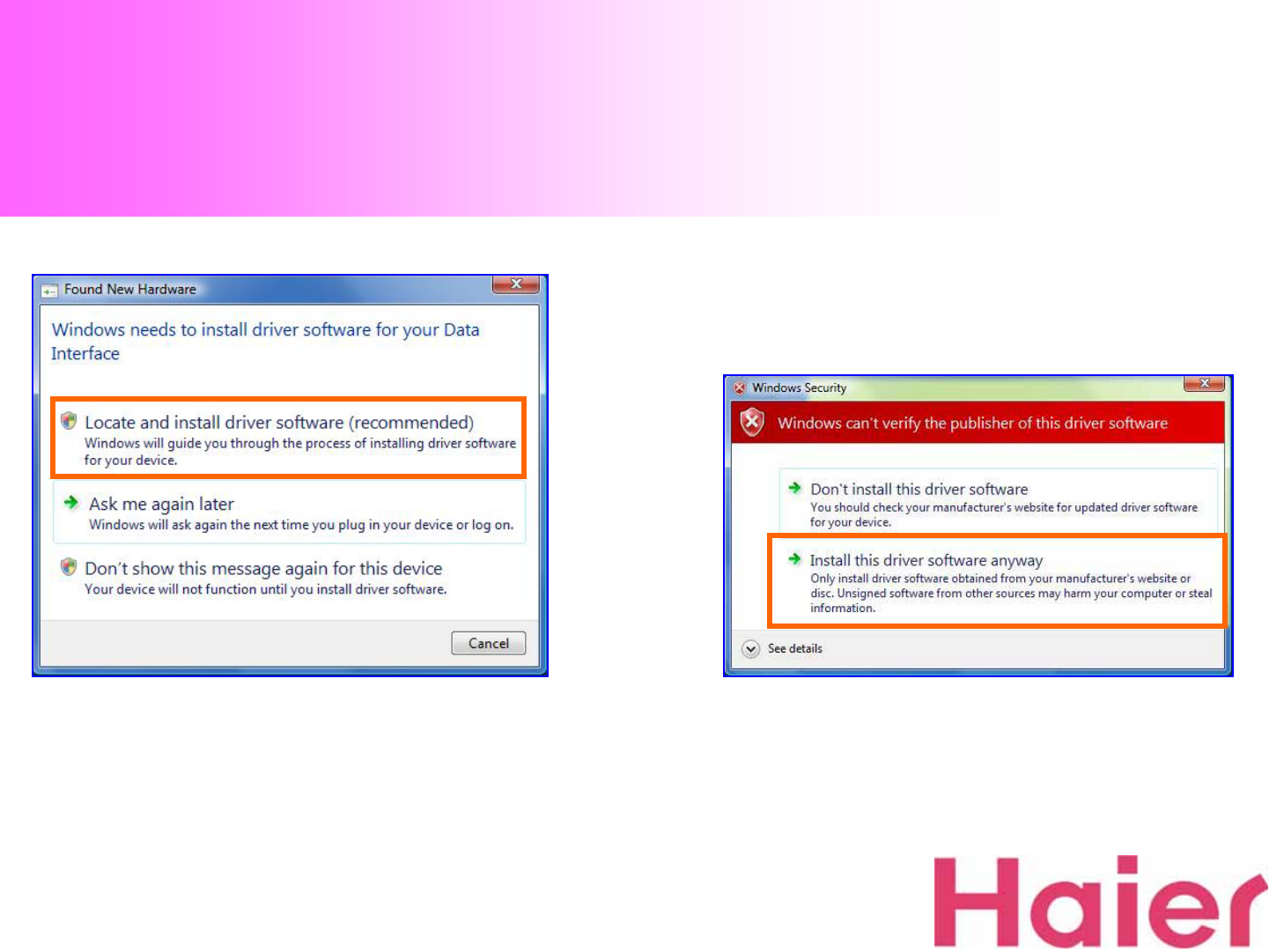
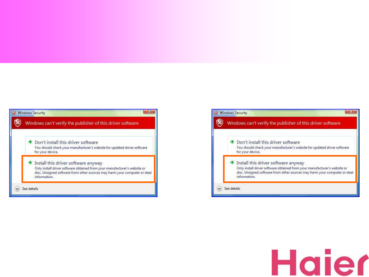
7. Please Check & Click the Orange color box as the
above to install U802T driver 8. Please Check & Click the Orange color box as above
to install U802T USB Data Modem driver
1. Installation – Windows Vista
10. Please Check & Click the Orange color box as the
above to install U802T GUI Port driver
9. Please Check & Click the Orange color box as the
above to install U802T DIAG Port driver
1. Installation – Windows Vista
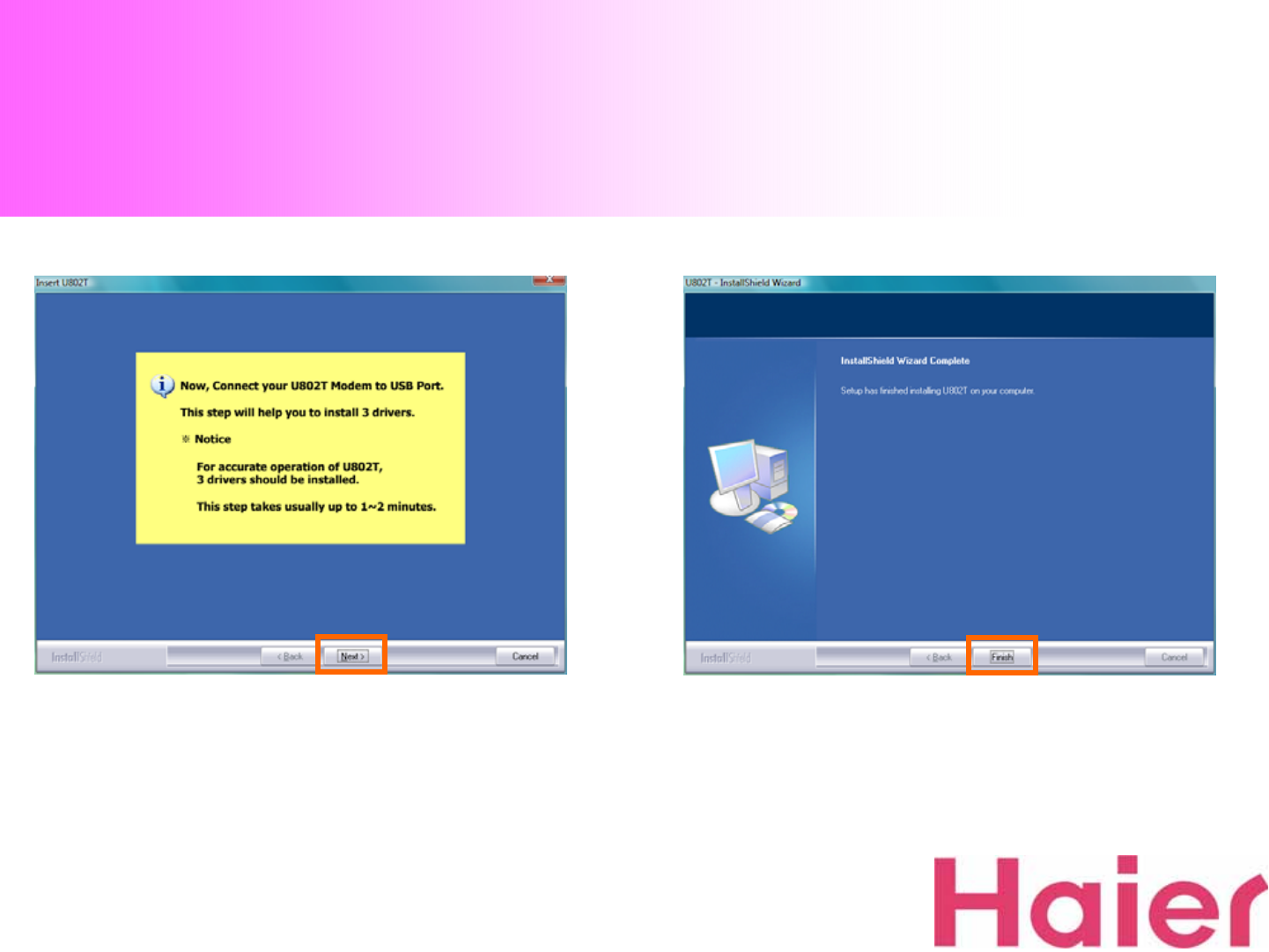
11. Please Click “Next”button after finishing all the
Installation of 3 drivers 12. Click “Finish”button to complete the installation
of U802T
1. Installation – Windows Vista
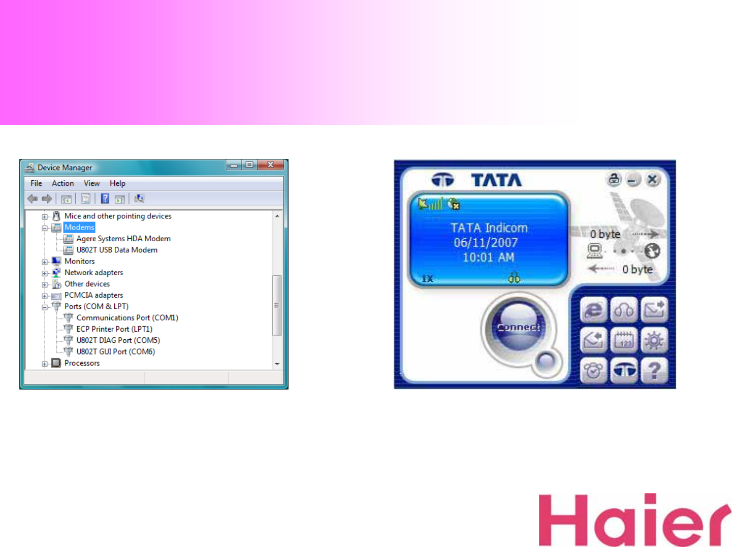
13. Open the Device Manager for Checking out the
driver has installed correctly 14. When you start the GUI, the screen will be displayed as
above (The default banner is “TATA Indicom”)
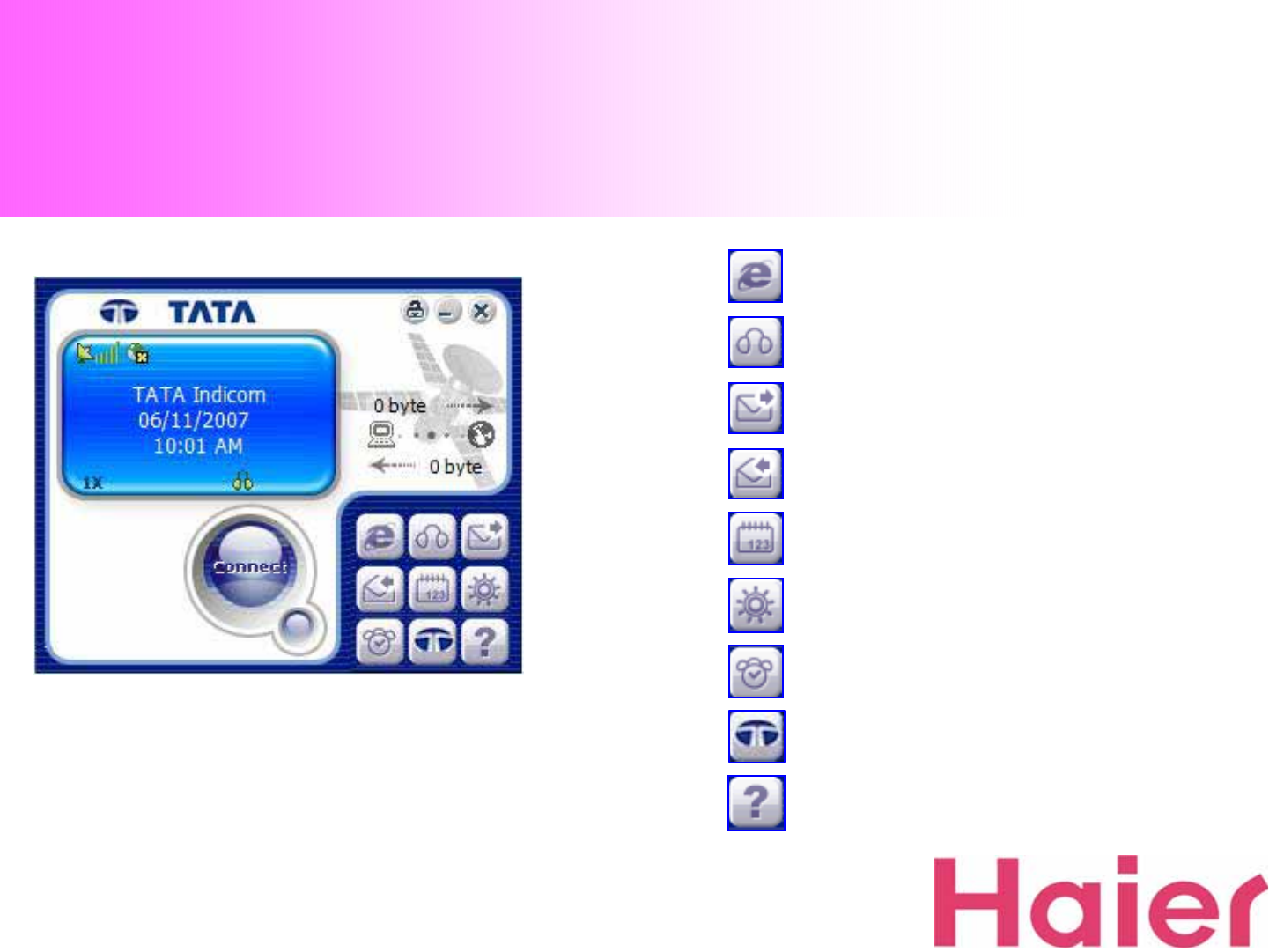
2. UI Features Instruction
Data
Voice
SMS
SMS Receive
Phonebook
Settings
Information
www.tataindicom.com
About
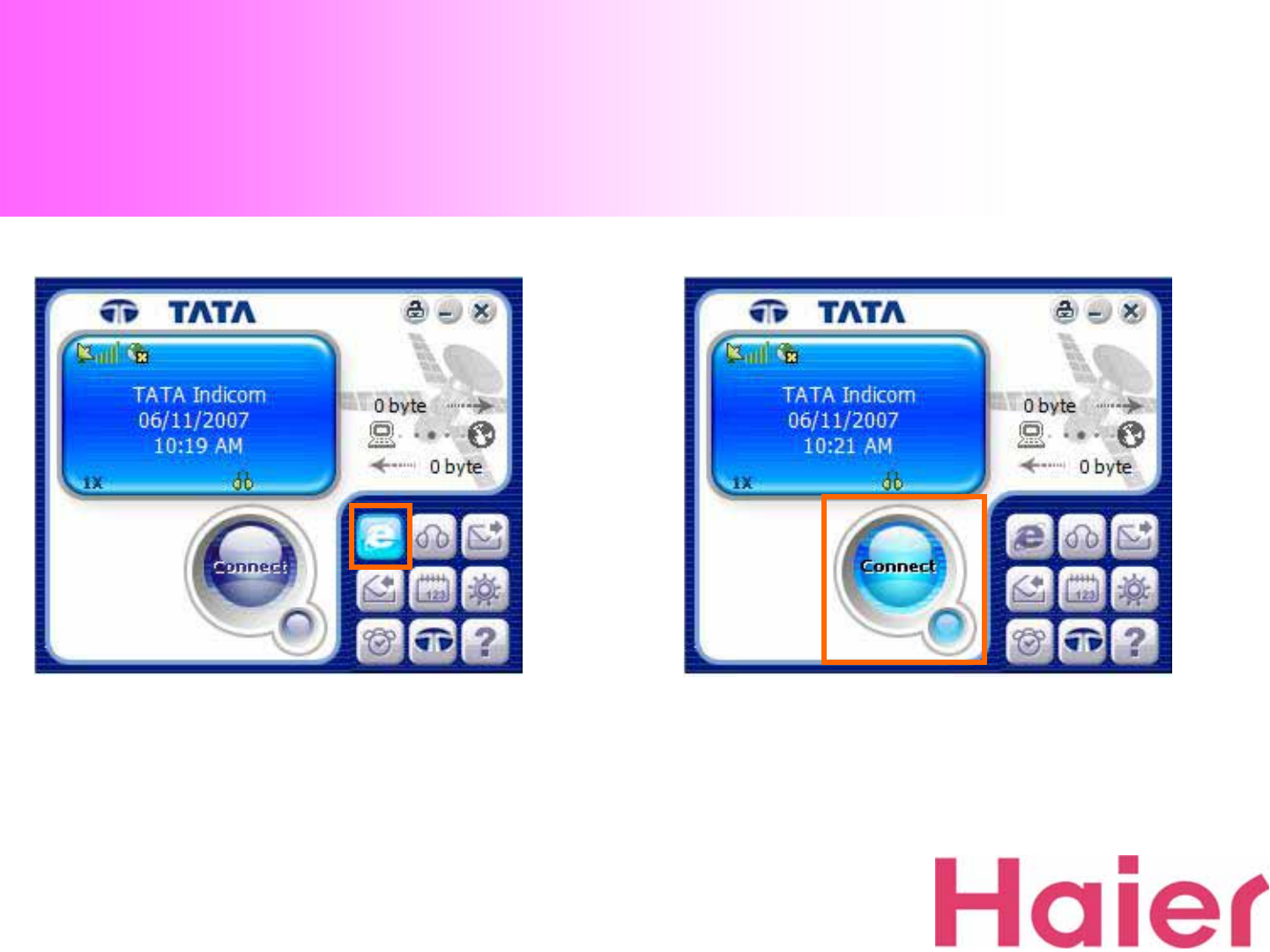
3. Data Connection & Disconnection
1. To change the screen for Data Connect (Internet),
please click the “Data”Icon 2. To connect the Data (Internet), please click the
“Connect”button
※ Before connecting to Data, Must check the valid ID,
Password & numbers (
Please see 8-1. Data Service
Terminal Settings
)
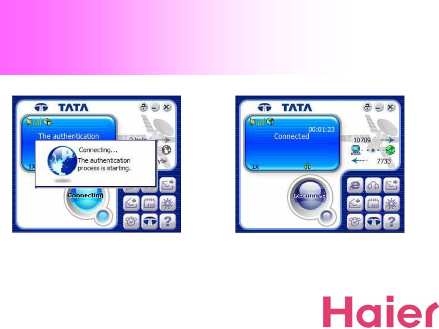
3. Data Connection & Disconnection
3. Wait for the Data Connecting (Internet) process.
After connected properly, the Internet Browser will be
started
4. If the Data Connection is properly connected, the
“Connected”Message will be displayed as the above
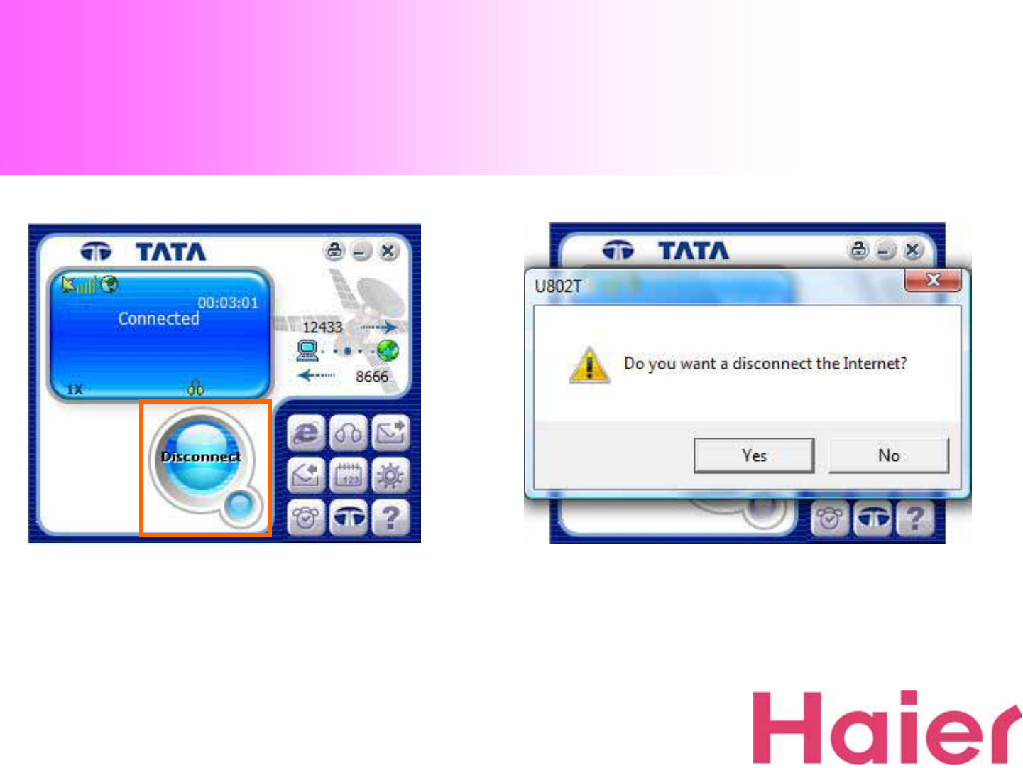
3. Data Connection & Disconnection
5. To disconnect the Data Connection (Internet),
Click “Disconnect”button 6. To click “Yes”button for disconnect, but “No”for
cancellation of the disconnection
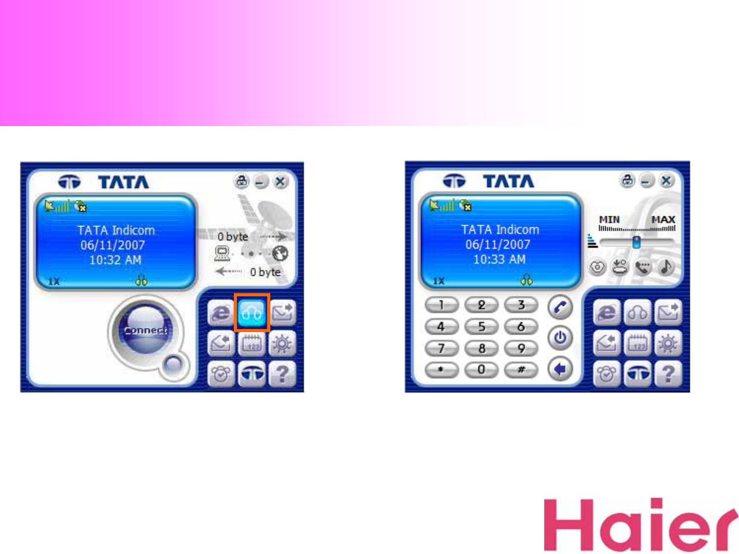
4. Voice call Connection & Disconnection
1. For Voice call, click the “Voice”Icon 2. When you click the Voice call button, the above
screen with dial-pad will be displayed
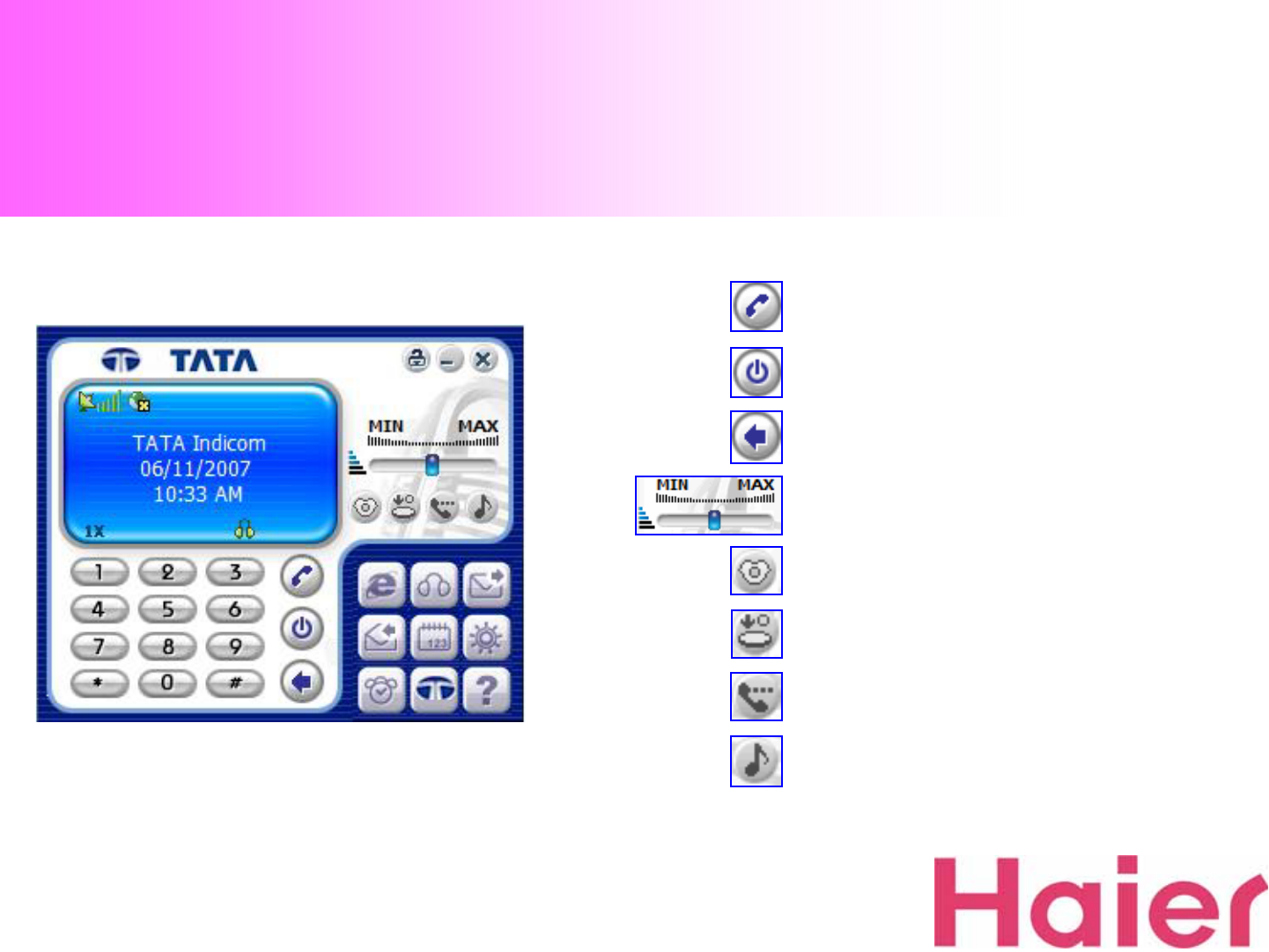
4. Voice call Connection & Disconnection
Call
End
Cancel
Volume (Voice)
Silent (When Silent mode)
Tone Silent (When Voice calling)
Voice Mute (When Voice calling)
Volume (Sound & Key Tone)
-Voice call Menu-
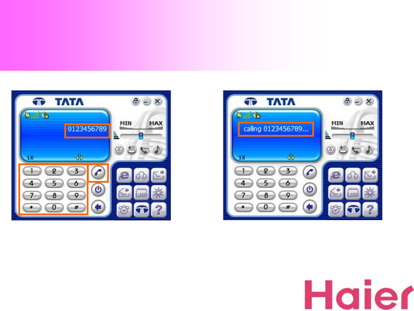
4. Voice call Connection & Disconnection
3. To make a Voice call, STEP ①Dial to wish numbers,
STEP ②Confirm the numbers, STEP ③Press call 4. Calling Screen
②
①③
①③
①③
③③
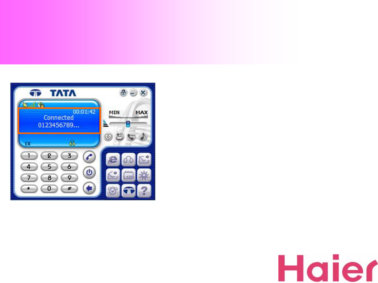
4. Voice call Connection & Disconnection
5. When successfully connected to wish numbers ,
the screen would be changed as the above
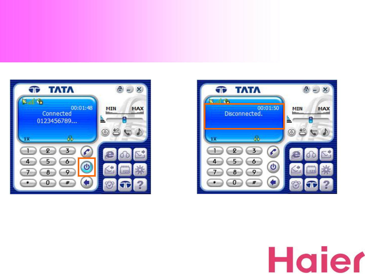
4. Voice call Connection & Disconnection
6. To disconnect the Voice call, press “End”Icon. 7. When disconnected properly, the screen would be
changed as the above
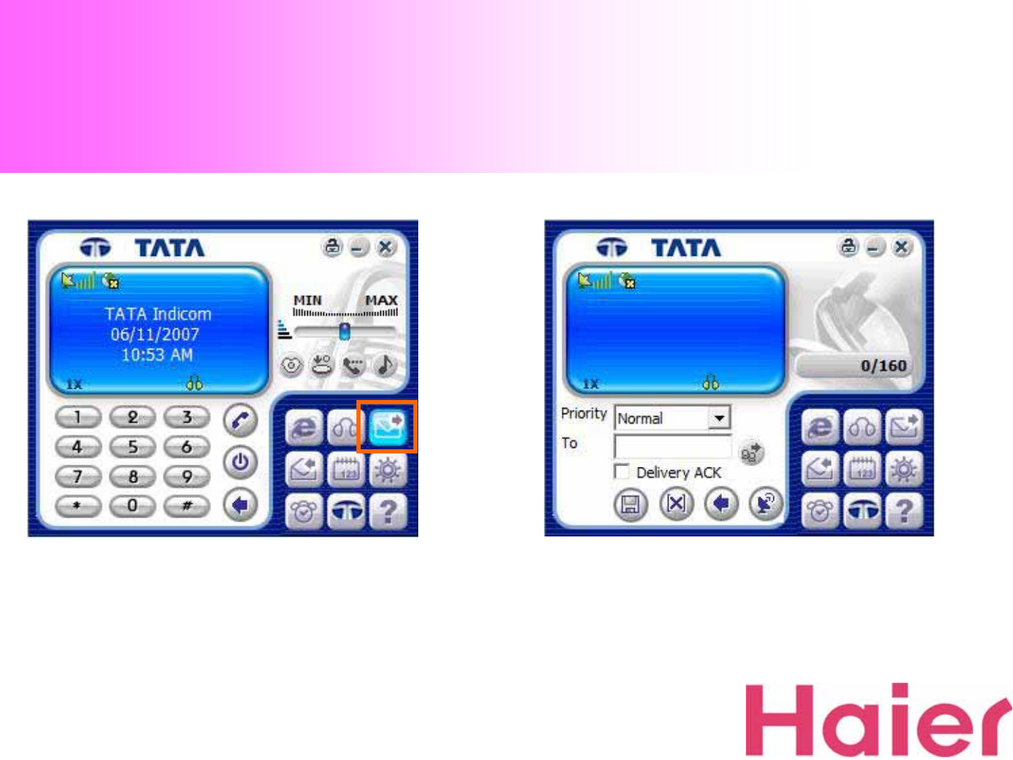
5. SMS Sending
1. To send SMS, just click the “SMS”Icon 2. SMS Screen
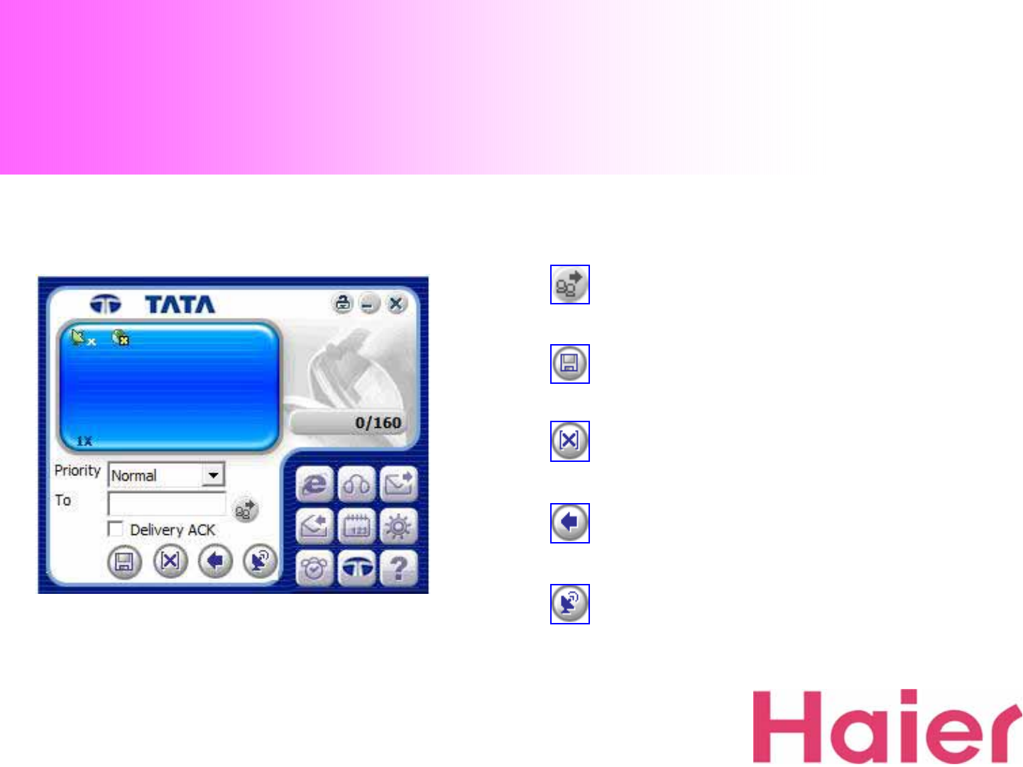
5. SMS Sending
-SMS Sending Menu-
ADD
All Clear
Cancel
Send
SAVE
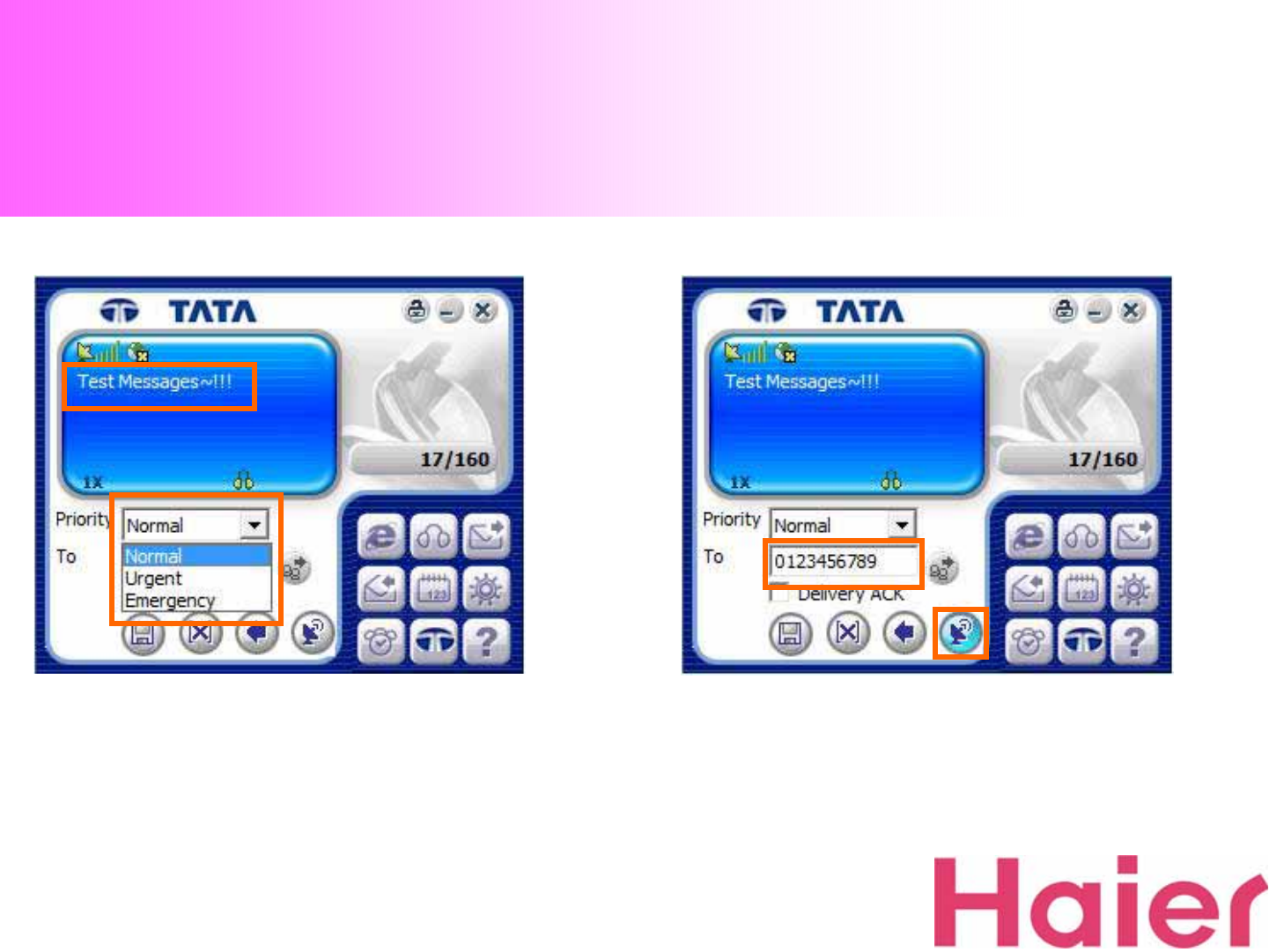
5. SMS Sending
3. To send SMS, STEP ①Type wish message, STEP ②
Choose Message type 4. STEP ③Type the numbers that you want to
send message, STEP ④Press “Send”Icon
②
①
③④
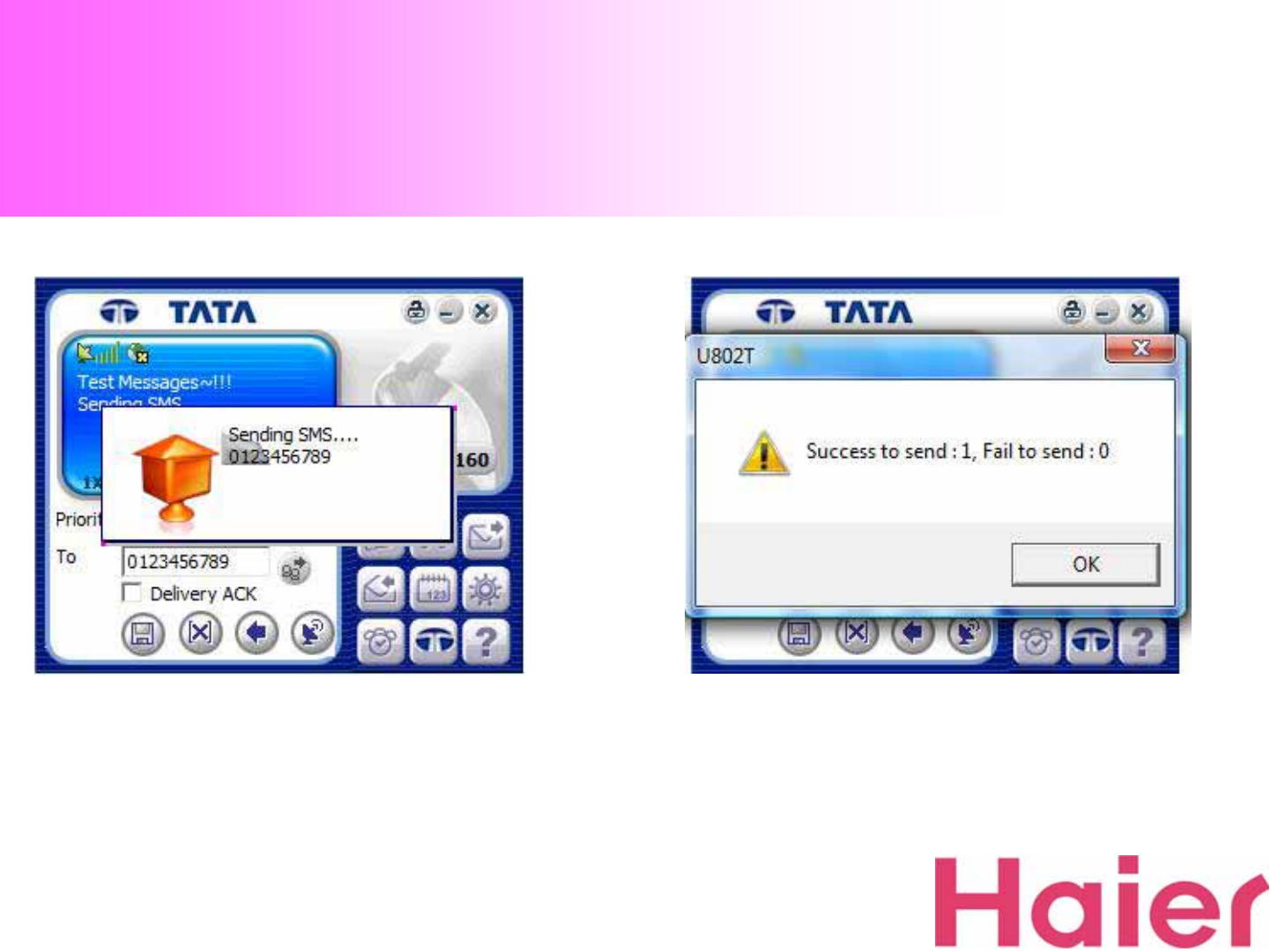
5. SMS Sending
5. SMS Sending process screen…6. After Sending SMS, a result window would be shown
whether succeeded or failed
5. SMS Sending
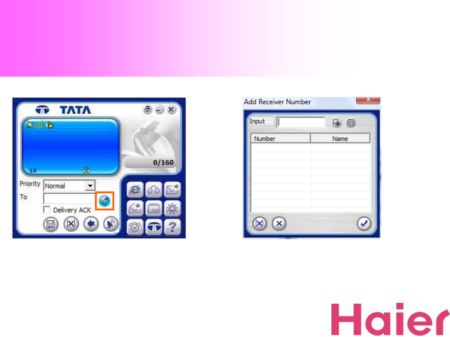
7. Click “Add”Icon when you desire to send the same
SMS to several phone numbers
If you use this function, the new screen will be pop-up
as the Right
5. SMS Sending
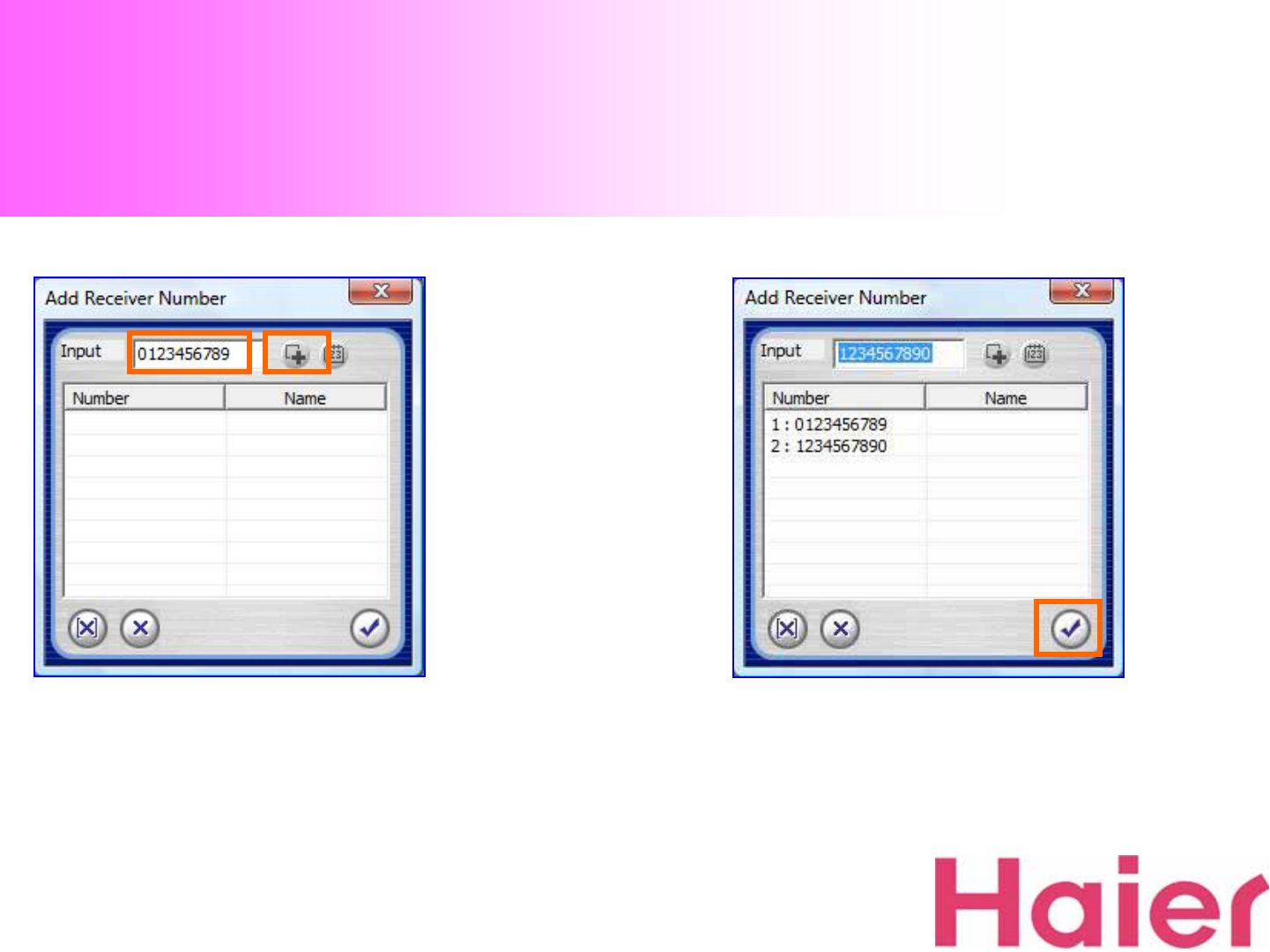
8. Type a desired call number and click “Add”Icon to
another desired numbers 9. After input numbers as much as desired, just press
the “Confirm”Icon to send message
5. SMS Sending
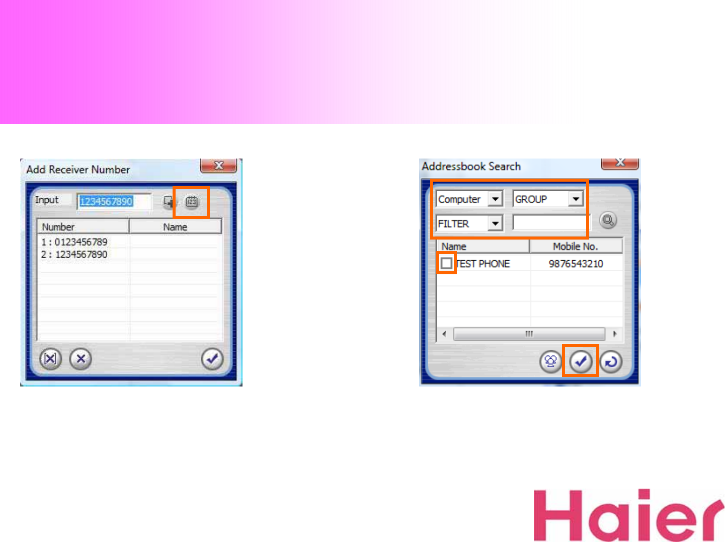
10. If you want to search a call number from computer,
click a Search Phonebook button 11. Select the category and browse the phone number
6. SMS Receiving
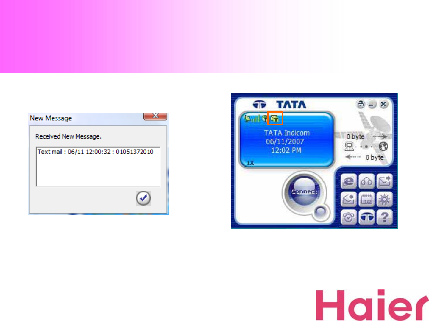
1. When new SMS is received, the New Message
window will be pop-up.
The received SMS will be saved on Received SMS box
2. If there is a un-read messages, “Message Icon”will
be displayed as the above until checking the message
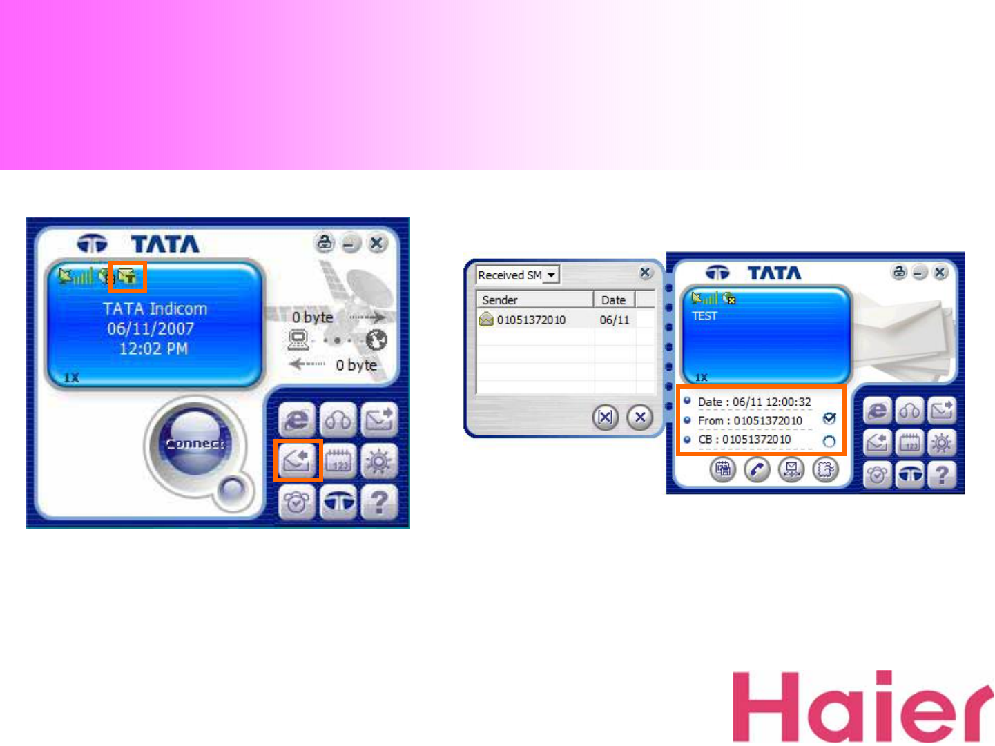
6. SMS Receiving
3. To check the new SMS, click “SMS Receive”
Icon. The read message is automatically saved 4. When you check the message, the time &
sender information is displayed as the above
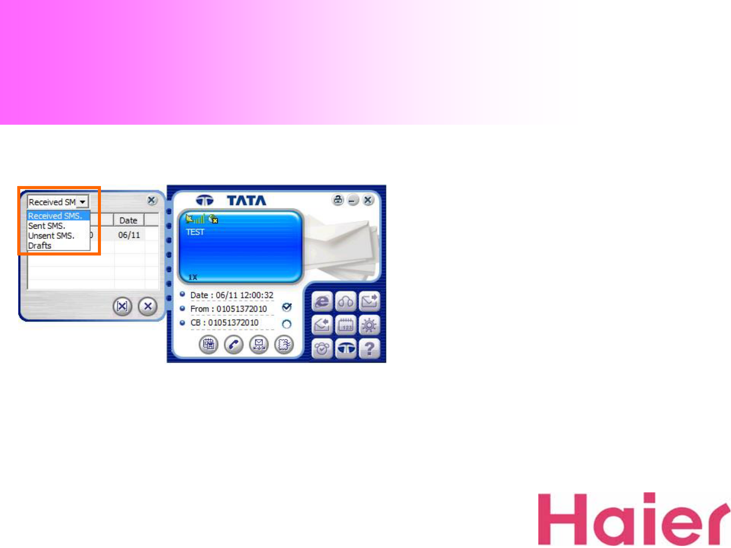
6. SMS Receiving
5. From the category, You can also check not only “Received
SMS”but also “Sent SMS”& “Unsent SMS”& “Drafts”
information
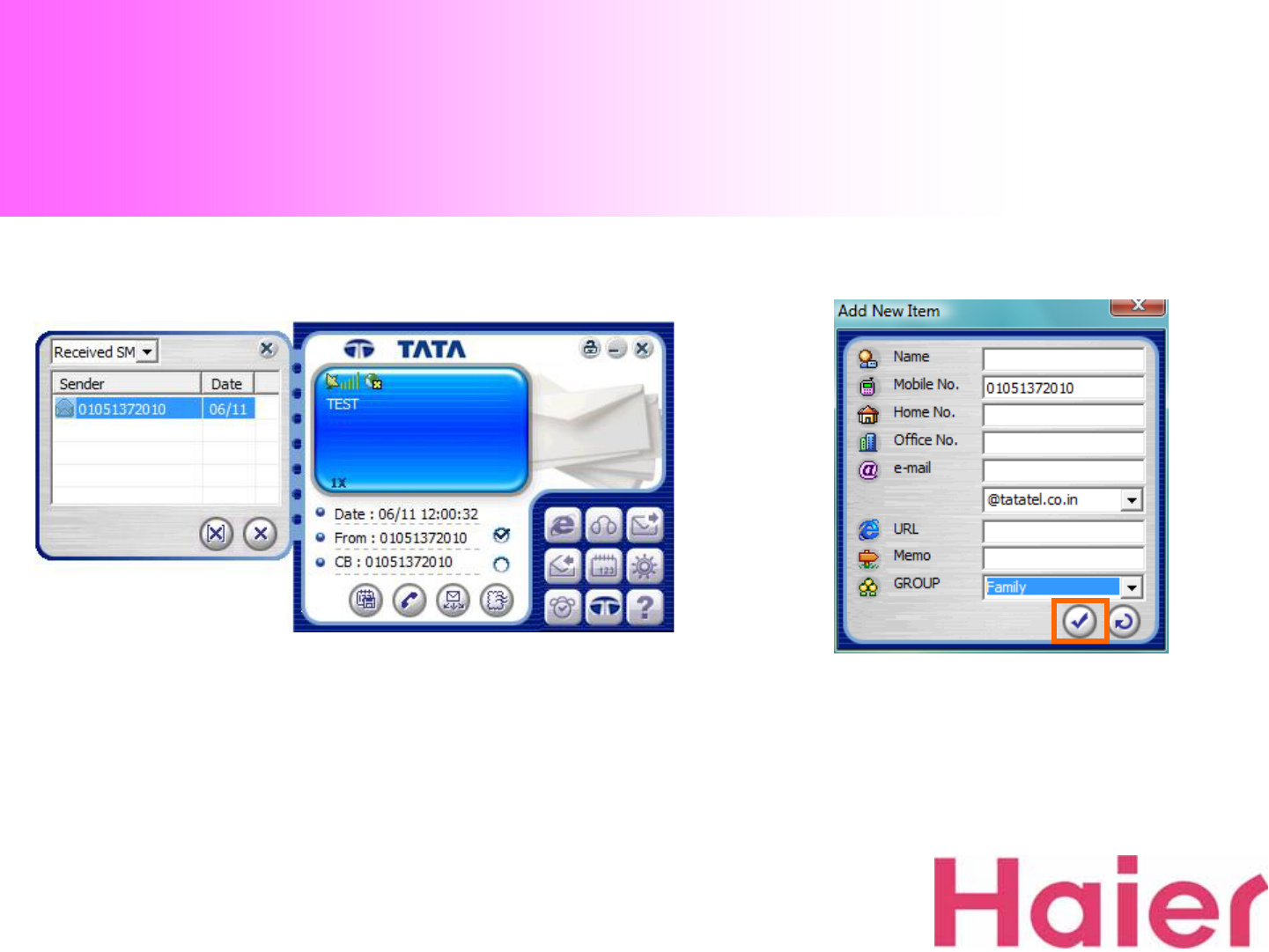
6. SMS Receiving
7. Fill in the information as your desire
Then press “Confirm”Icon to save
6. If you desire to save the “Received / Sent number”
to Phonebook , just press “Save”Icon then the Right
screen will be pop-up
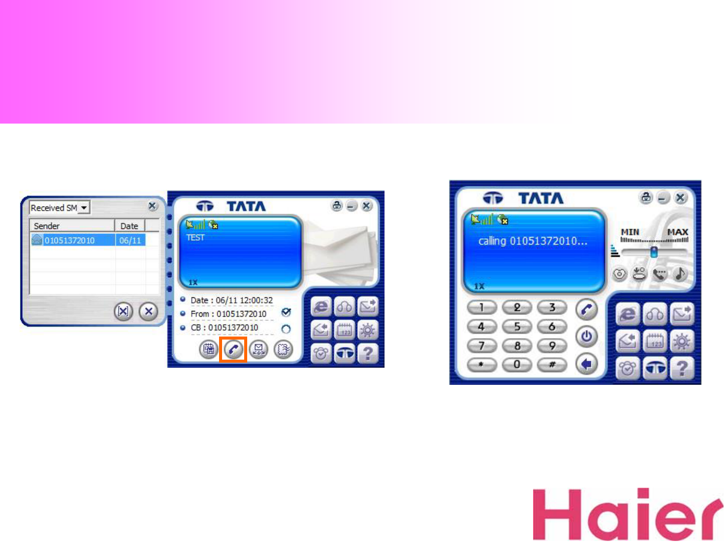
6. SMS Receiving
8. You can also directly forward the number (Choosing
“From”or “CB”) for Voice call with the “Call”Icon 9. Calling process screen…
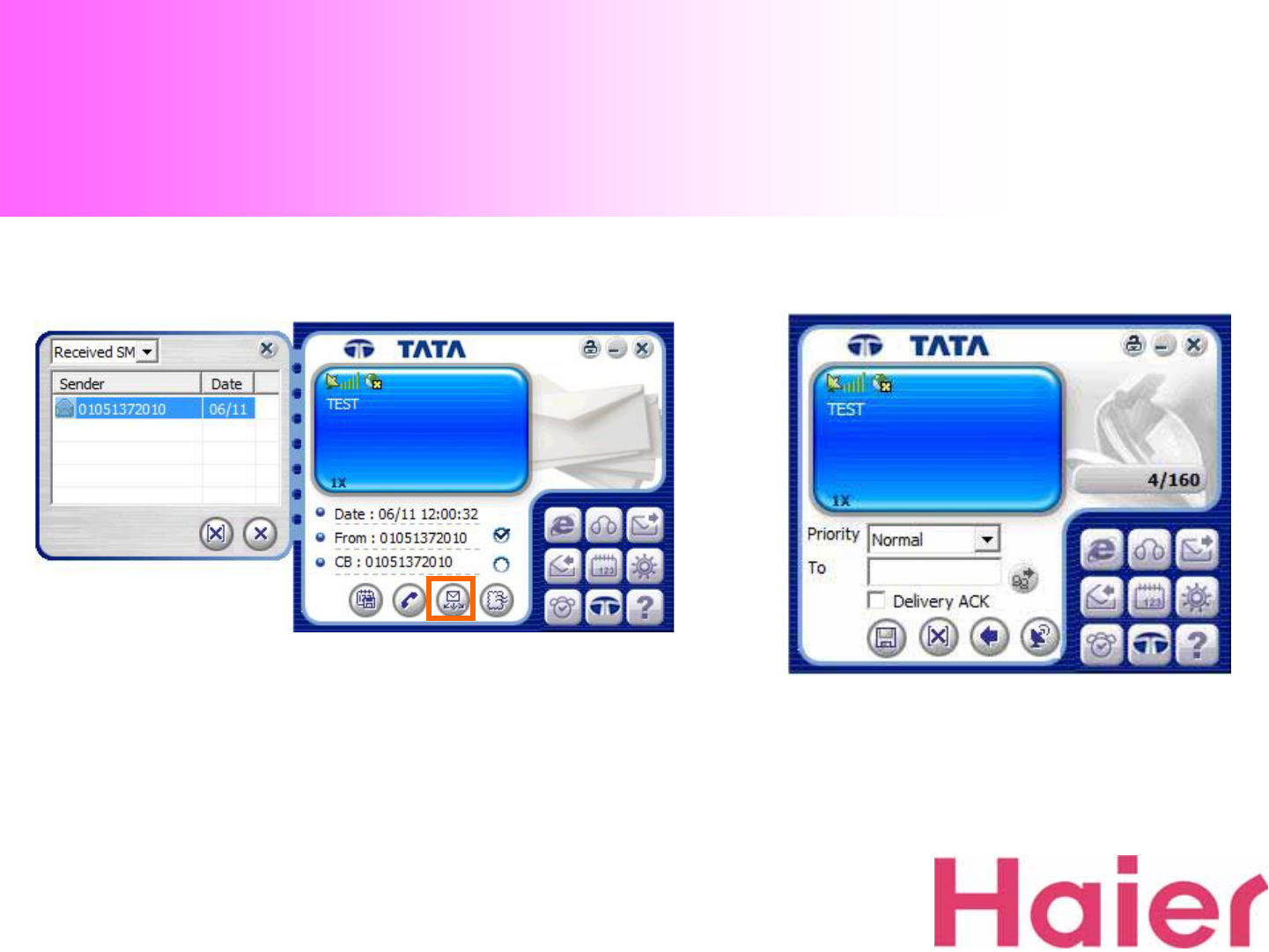
6. SMS Receiving
10. When you press the “Forward”Icon, the received
message can be delivered to another desired number 11. Type your desired number to forward
the message

6. SMS Receiving
12. If you want to reply to sender number, just choose
“From”or “CB”from above field then click “Reply”Icon 13. Type your message on the screen
same as “SMS Sending”Instruction
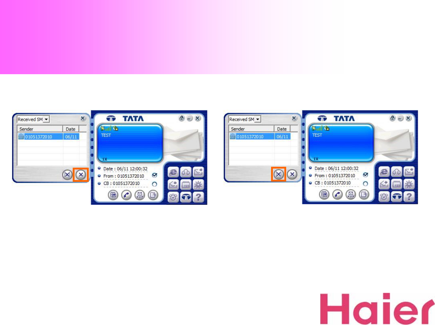
14. If you want to delete individual SMS, select SMS to
be deleted and click “Delete”button 15. You can select not only “Received SMS”but also “Sent
SMS”& “Temp SMS”in the category then easily delete whole
saved messages with clicking “Delete All”Icon
6. SMS Receiving
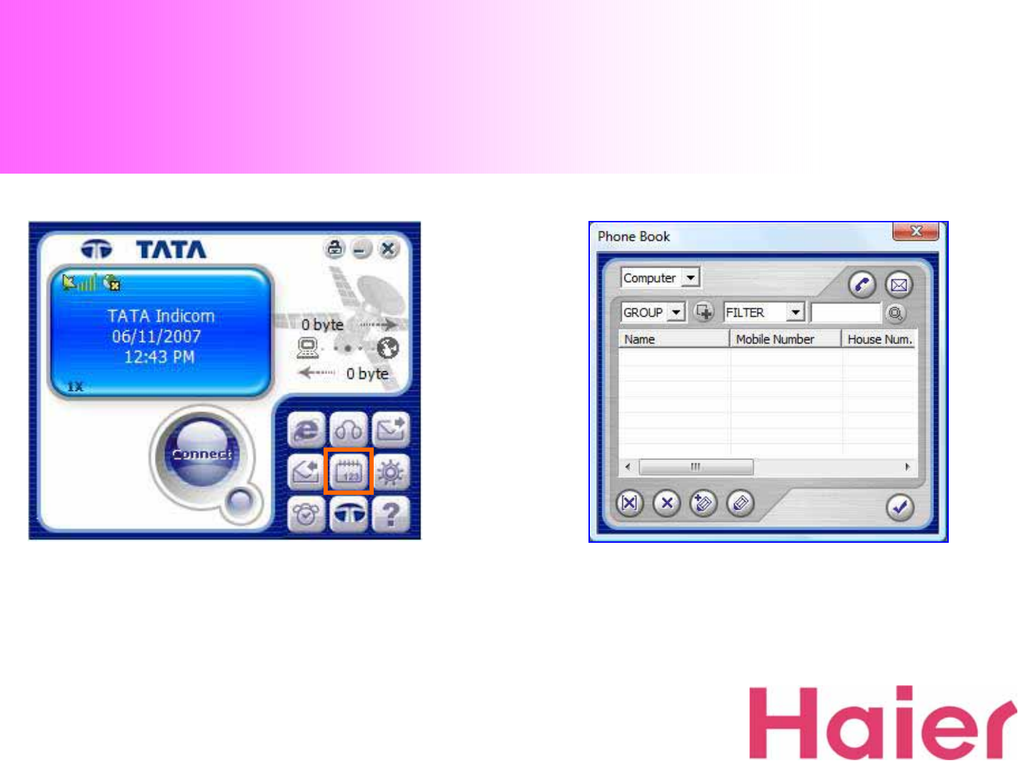
7. Phonebook
1. If you want to add / remove the call number from
phonebook, Click “Phonebook”Icon 2. When click the Phonebook Icon, Phonebook window
will be pop-up as the above
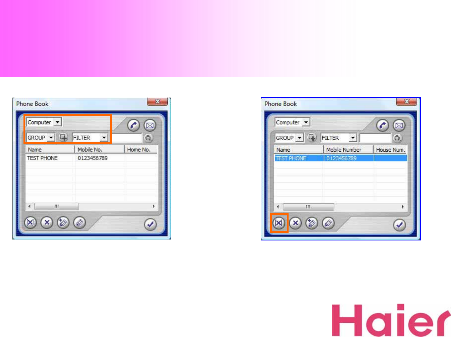
7. Phonebook
3. Select the location where the lists saved 4. If you want to delete all of specific group’s numbers
at once, just select the desired “GROUP”then click the
“Delete All”Icon
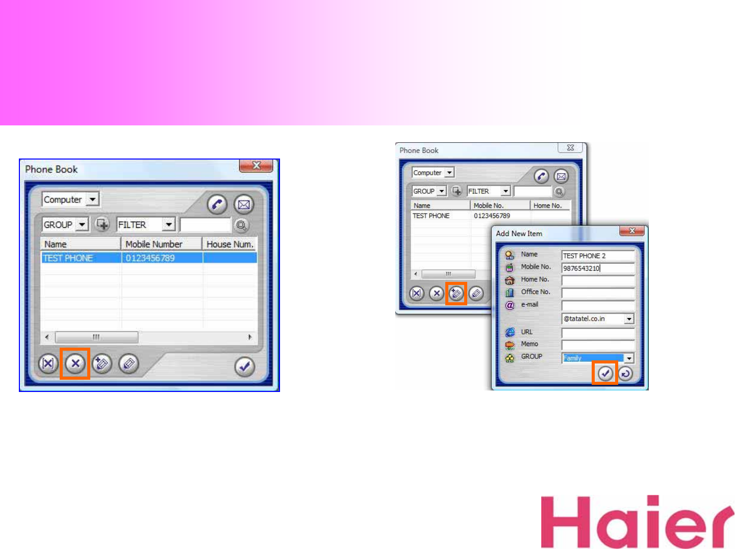
7. Phonebook
5. If you want to delete an individual phone number,
select the number and click Delete button 6. If you want to save new call number, just click “Add”
Icon then easily store new number
After filling, just click “Confirm”to save
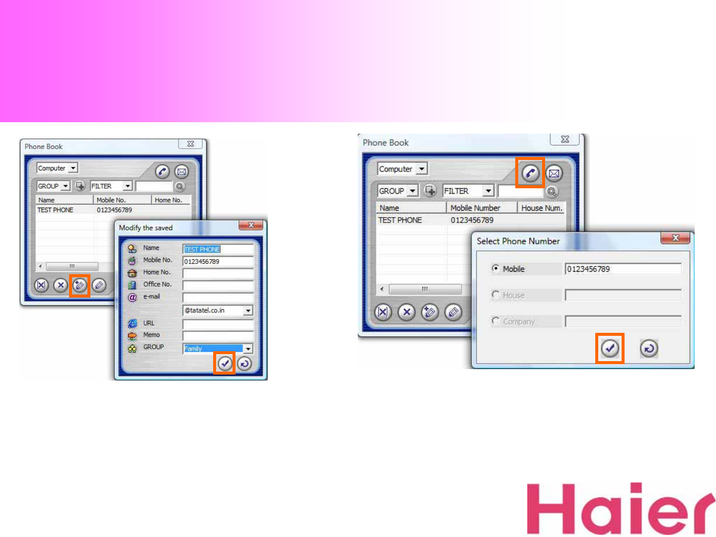
7. If you want to modify the stored number & details,
just click “Modify”button 8. When you want to make a call from Phonebook, Select
the number then just click the “Call”Icon
7. Phonebook
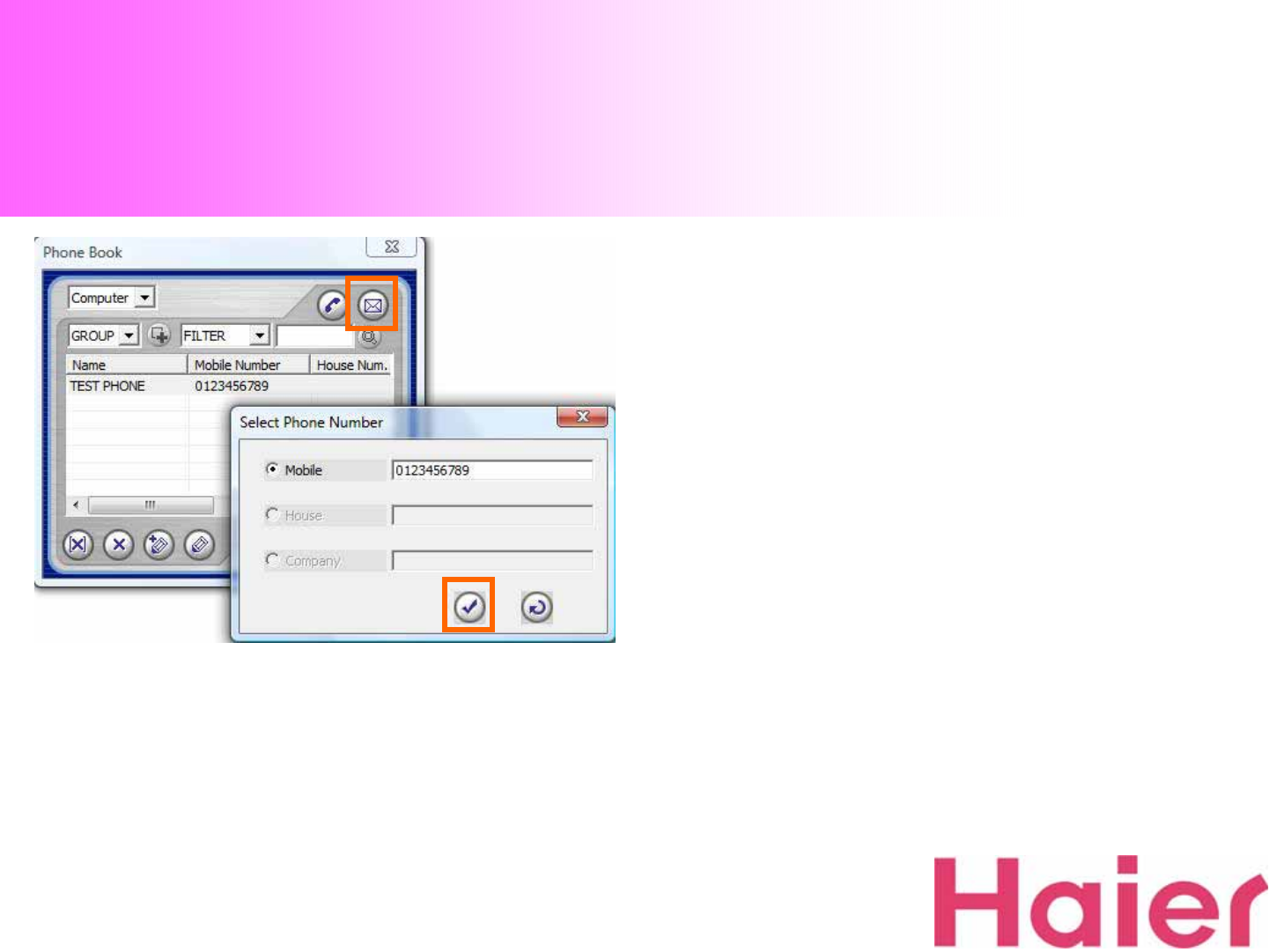
9. When you want to send a SMS from Phonebook, Select
the number then just click the “SMS” Icon as the above
7. Phonebook
8. Settings
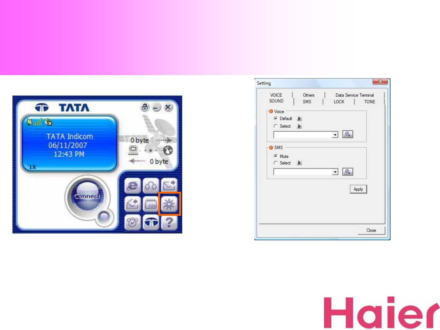
1. If you want to check or modify the settings, just click
“Setting”Icon as the above 2. When you start the “Setting”, the new window will be
pop-up as the above
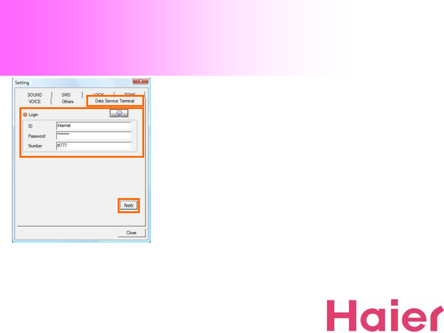
8. Settings
To connect to Server, you should input valid
ID & Password only
The Number should be #777
The step to setup is as the circle order
8-1. Data Service Terminal
③
①
②
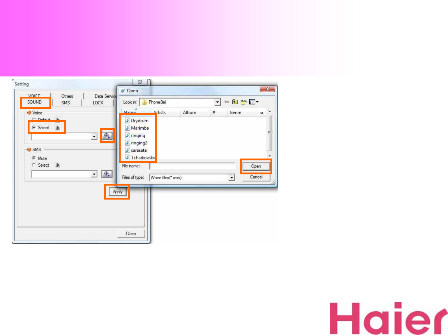
8. Settings
1. With Setting Menu, you can set the Bell Sound &
SMS Receiving Alarm from “SOUND”tab
The step to setup is as the circle order
8-2. SOUND
③
⑤
⑥
①
②
④
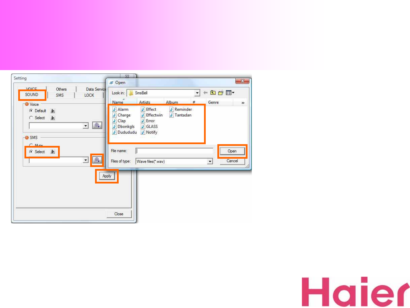
8. Settings
2. SMS Receiving Alarm is to be setup as the Circle
order
8-2. SOUND
①
②③
④
⑤
⑥
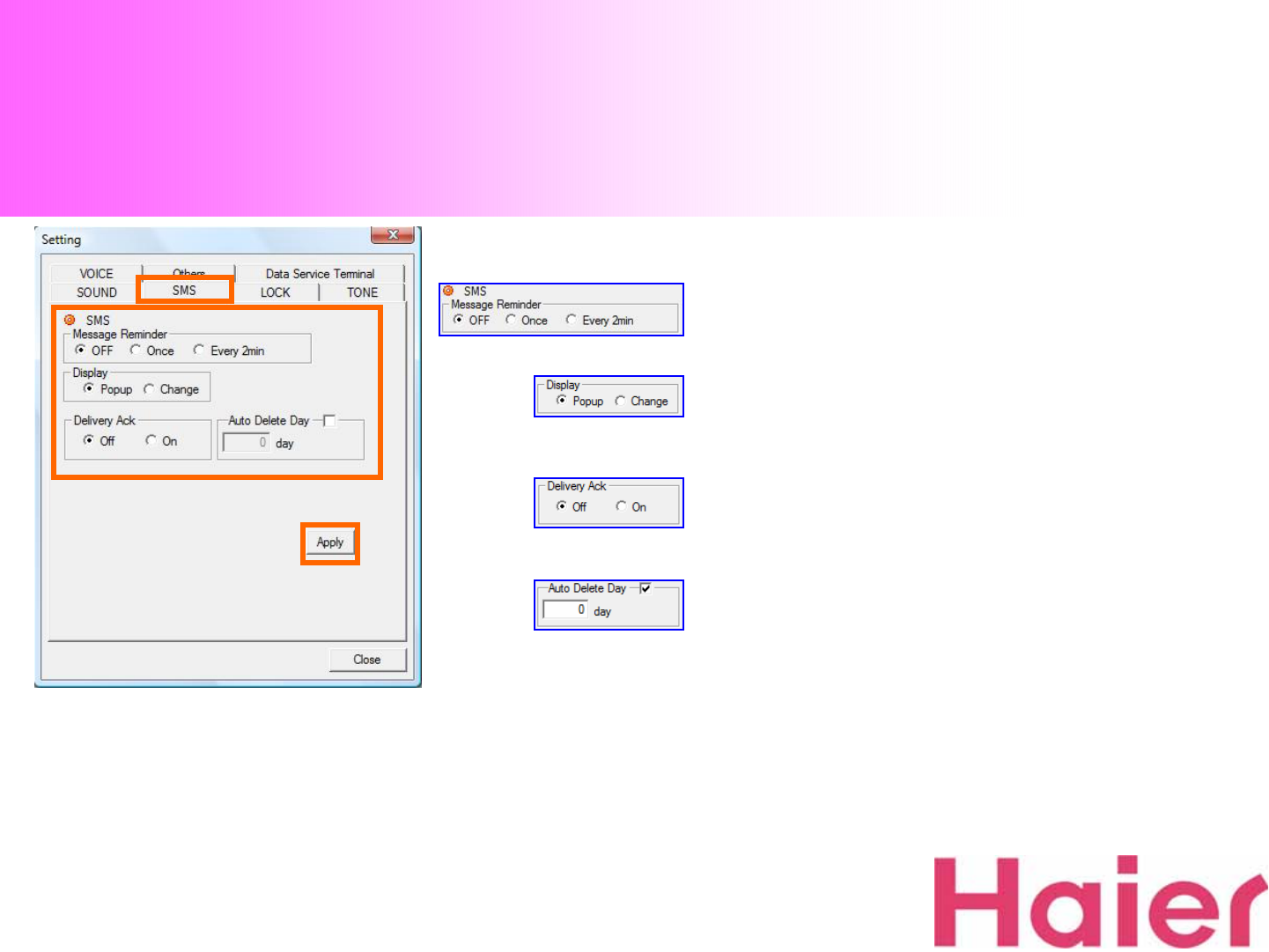
8. Settings
When receiving SMS, can be setup as just 1
time alarm only or alarm every 2 minutes or
alarm off
When receiving SMS, can be setup checking it
from Pop-up window or History list (Change)
If “Delivery Ack”is setup as On, can get the
confirmation of receiving SMS from receiver
when SMS sending
If want to delete the saved SMS automatically
by desired period, you can setup the period as
you want
The step to setup is as the circle order
8-3. SMS
③
①
②
8. Settings
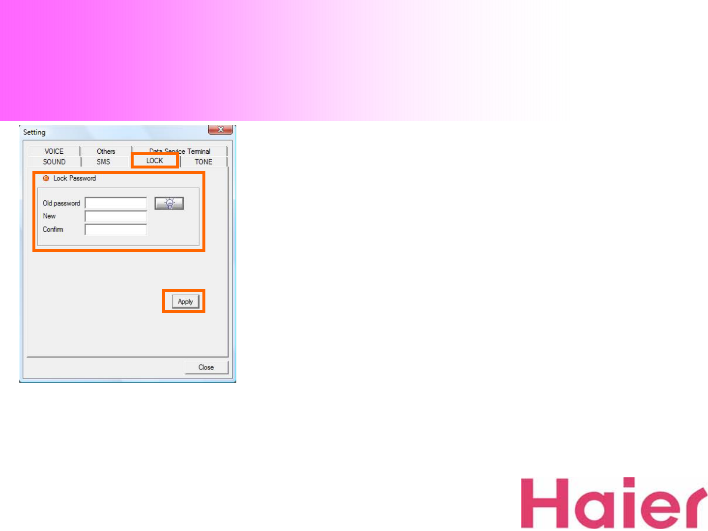
1. You can setup “Lock”for Call-Limit
The Password can be setup using numbers from 4 to 8 digits
The step to setup is as the circle order
8-4. LOCK
③
②①
8. Settings
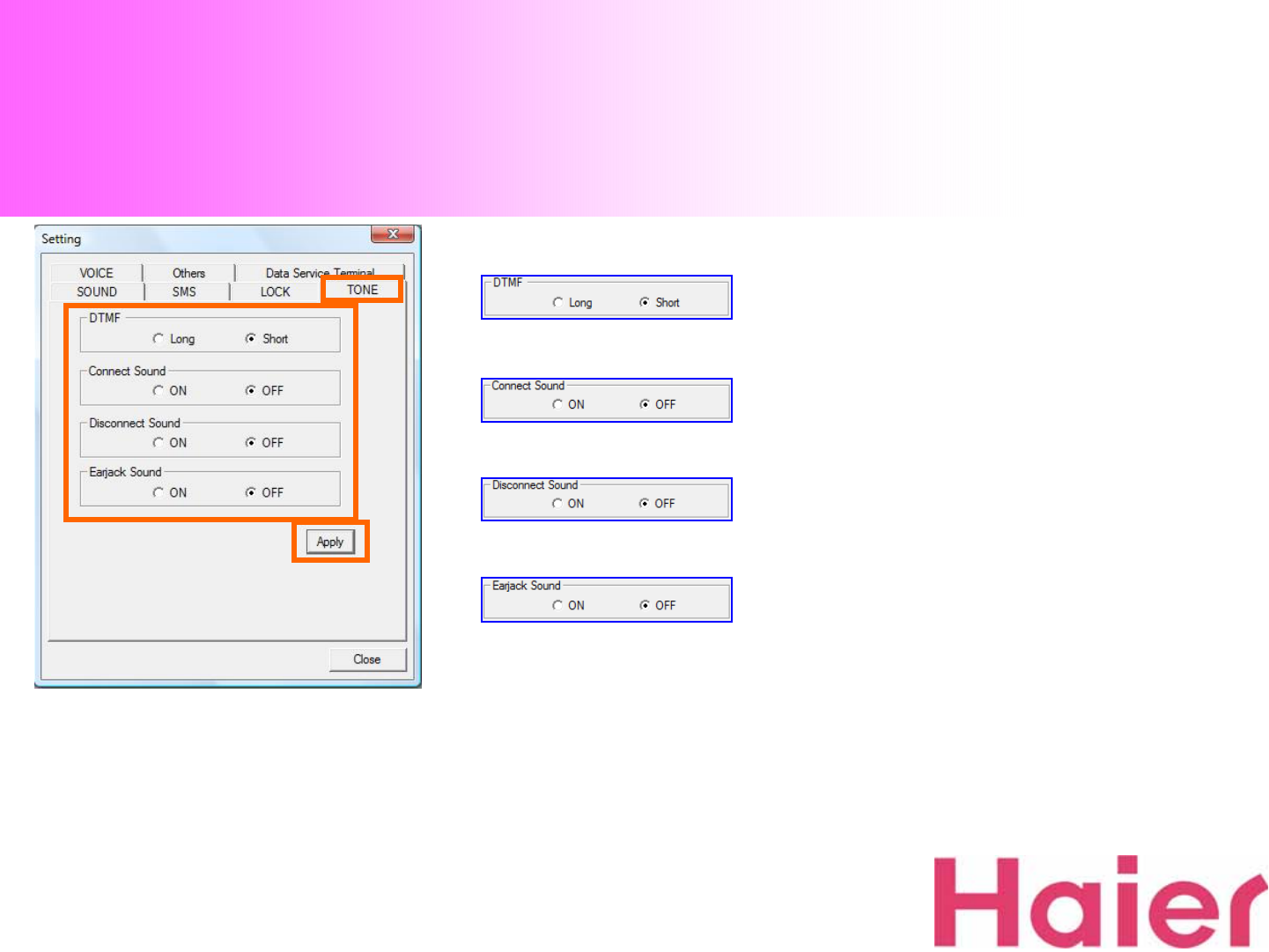
You can setup the length of Button Sound
Long / Short
You can setup Connection Sound On / Off
when call receiving or sending.
You can setup Disconnection Sound On / Off
when call disconnecting
You can setup Ring Sound On / Off when you
receiving call by earphone
The step to setup is as the circle order
8-5. TONE
③
②①
8. Settings
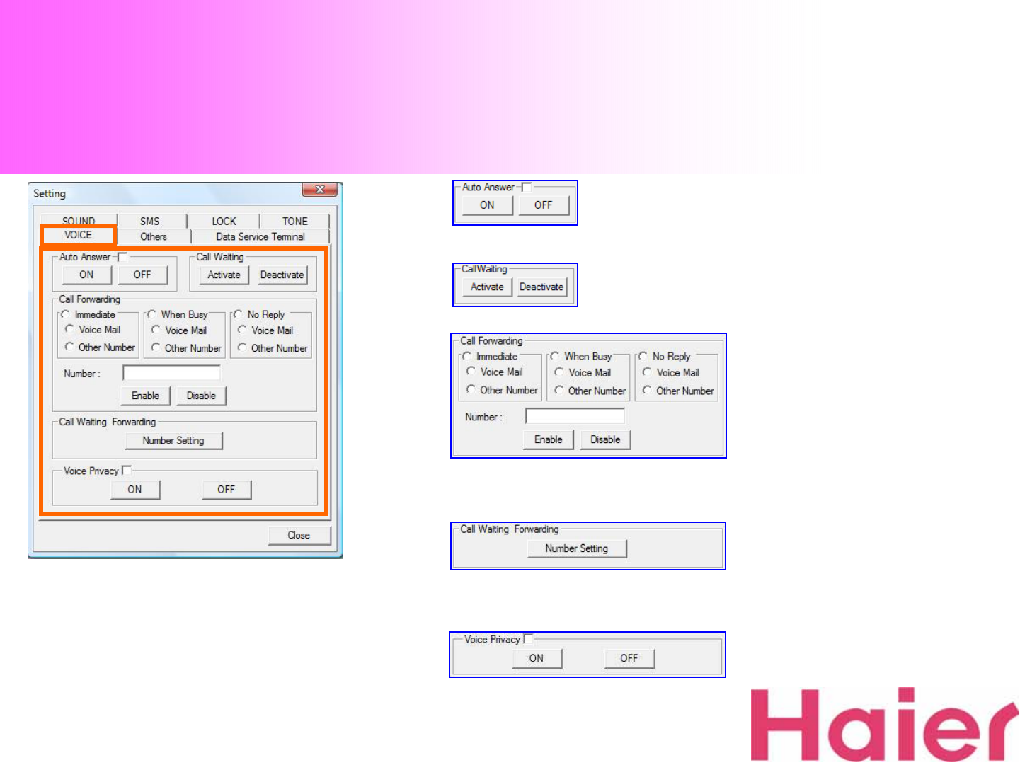
Lock for Voice call
Call Forwarding setup (You can changed other number,
reference to next page)
The step to setup is as the circle order
8-6. VOICE
②
①
Call Forwarding Number setup (You can changed other
number, reference to next page)
Auto Answer On (5 seconds) / Off
Call Waiting setup Activate / Disactive
8. Settings
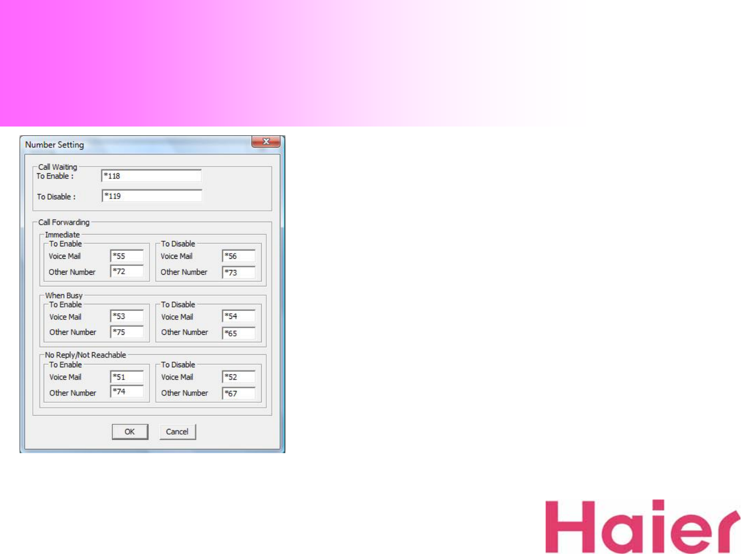
8-6. VOICE
Call Waiting and Call Forwarding Number Setting
You can changed default Number
8. Settings
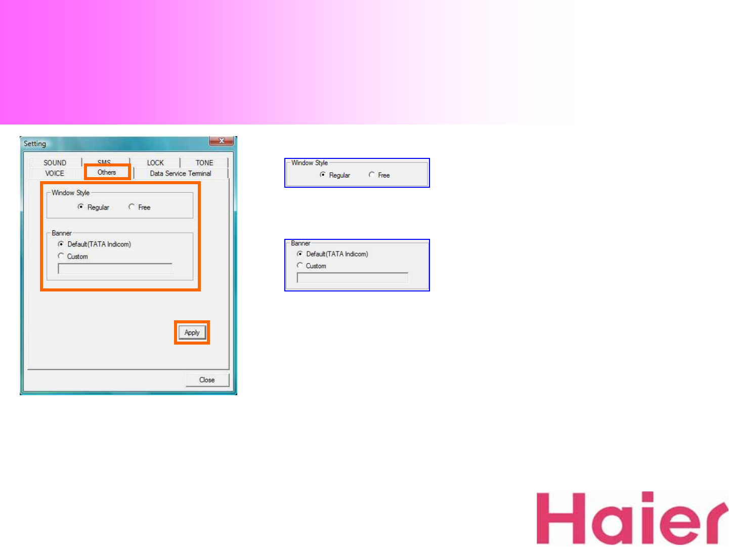
Window UI Style setup as Regular / Free
Banner Setup Default (TATA Indicom) /
Custom
If you select the “Custom”option, you can
write your own characters up to 16 digits
The step to setup is as the circle order
8-7. Others
③
②①
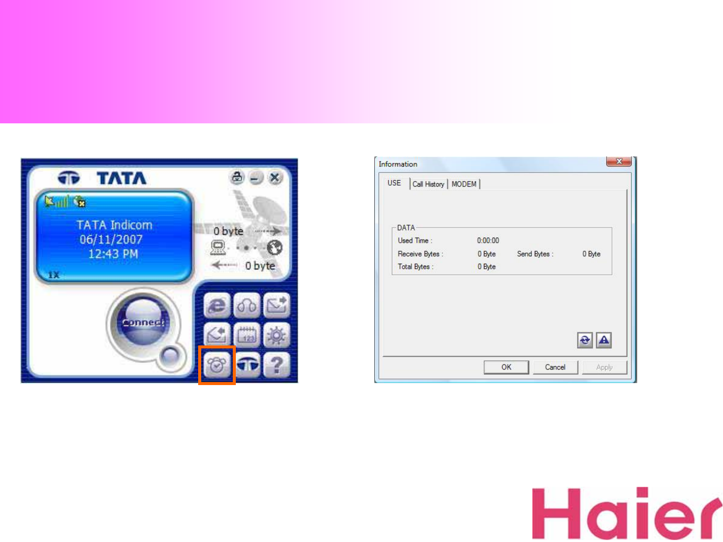
9. Information
1. With “Information”Icon, you can see the status of
Data using history, Voice call history & Modem
information
2. When you click “Information”Icon, new window will
be pop-up as shown
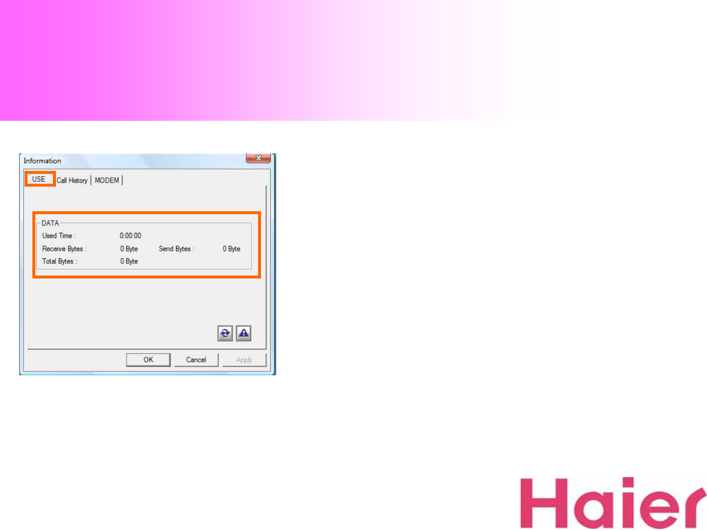
9. Information
1. Information → USE Tab, you can check your DATA
Status information as like the above
9-1. USE

9. Information
1. Information → DETAIL Tab, you can check your
Voice call Incoming, Outgoing, Missed & Data Usage
Information
Also you can easily connect Voice call & SMS Sening
using the Phone Number which is saved in the history
9-2. CALL HISTORY
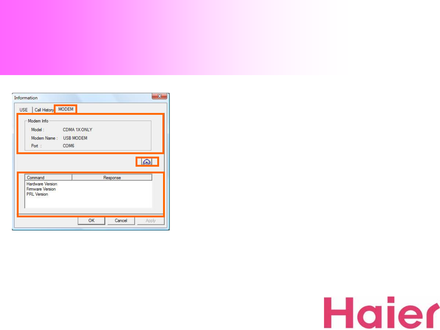
9. Information
1. Information → MODEM Tab, you can see the Modem
Status.
When you click “Modem Status” button, you can check
the “Hardware Version”, “Firmware Version” & “PRL
Version”
9-3. MODEM
9. Information
9-3. MODEM
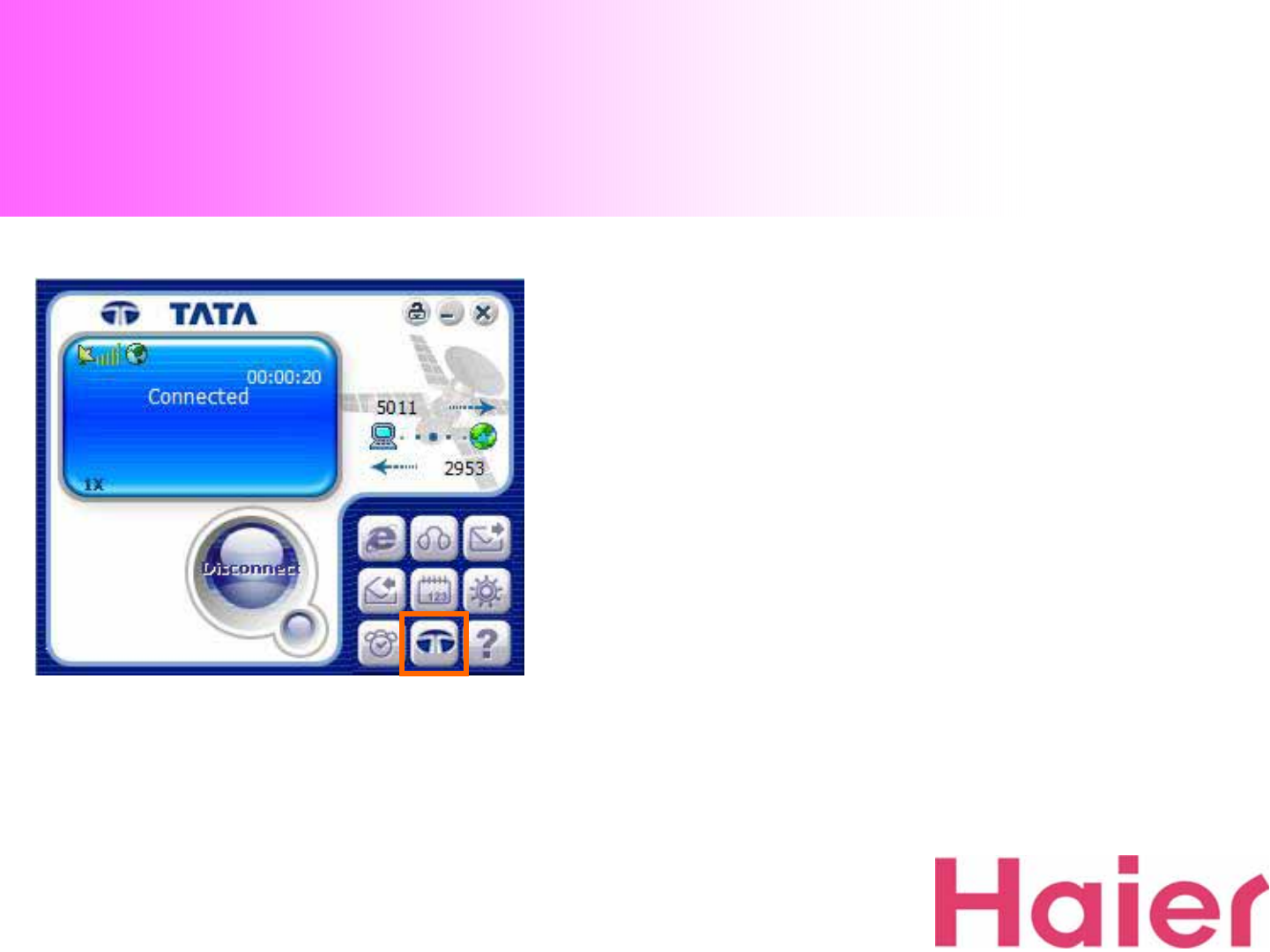
10. TATA Web Page Connection
1. While your U802T is connected to Data, and you would like to connect to “TATA
Indicom” Web Page, just click the “TATA Indicom” lcon on the GUI Screen
Only one step to click will lead you to “TATA Indicom” Web Page
(www.tataindicom.com)
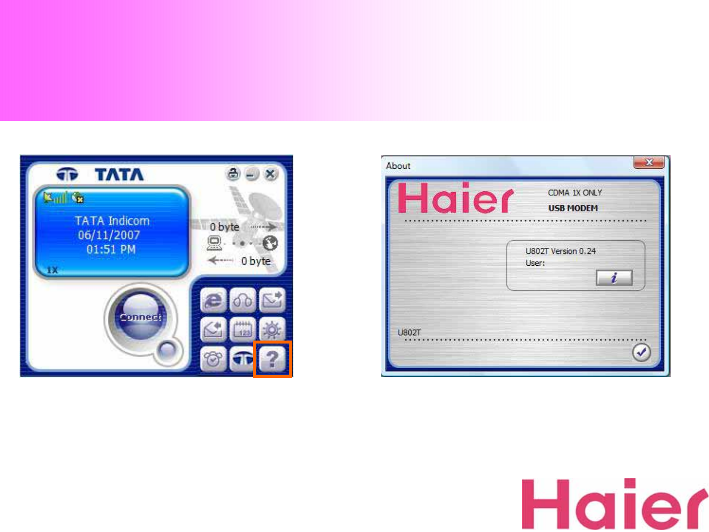
11. About
1. With “About” Icon, you can check the Modem
Information & GUI version as like the Right Screen
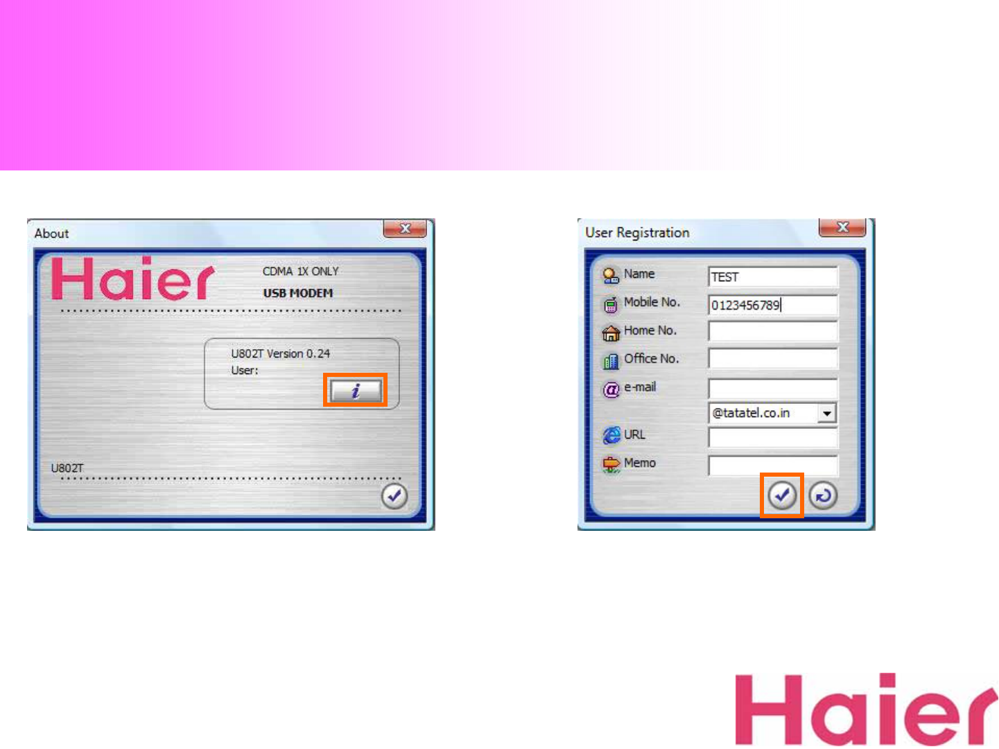
11. About
3. When you finish the filling, just click “Confirm”Icon
2. On “About” Information, you can register your
Information to Modem as like the Right Screen 3. When you finish the filling, just click “Confirm”Icon
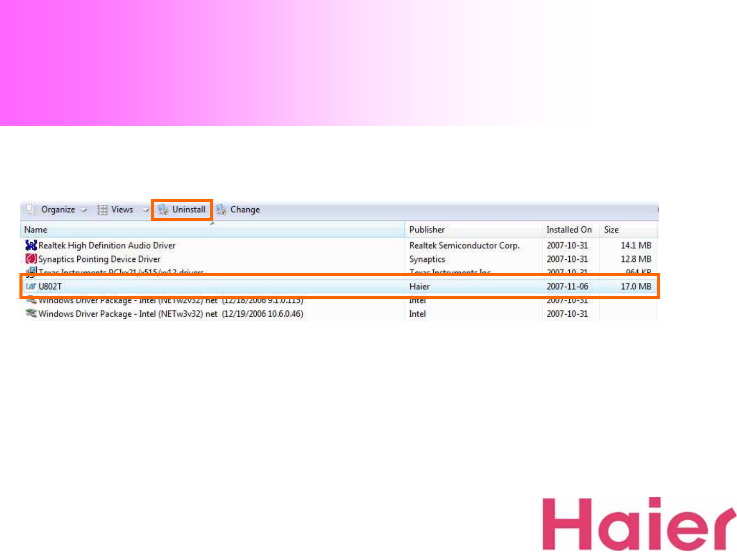
12. Un-Installation – Windows Vista
1. If you want to uninstall “U802T” Modem & Drivers from your computer, you
can select the “Program My Computer ÆUninstall Tab”, then select “U802T”
shield as like the above
Note: It doesn’t require for U802T to be connected in USB port
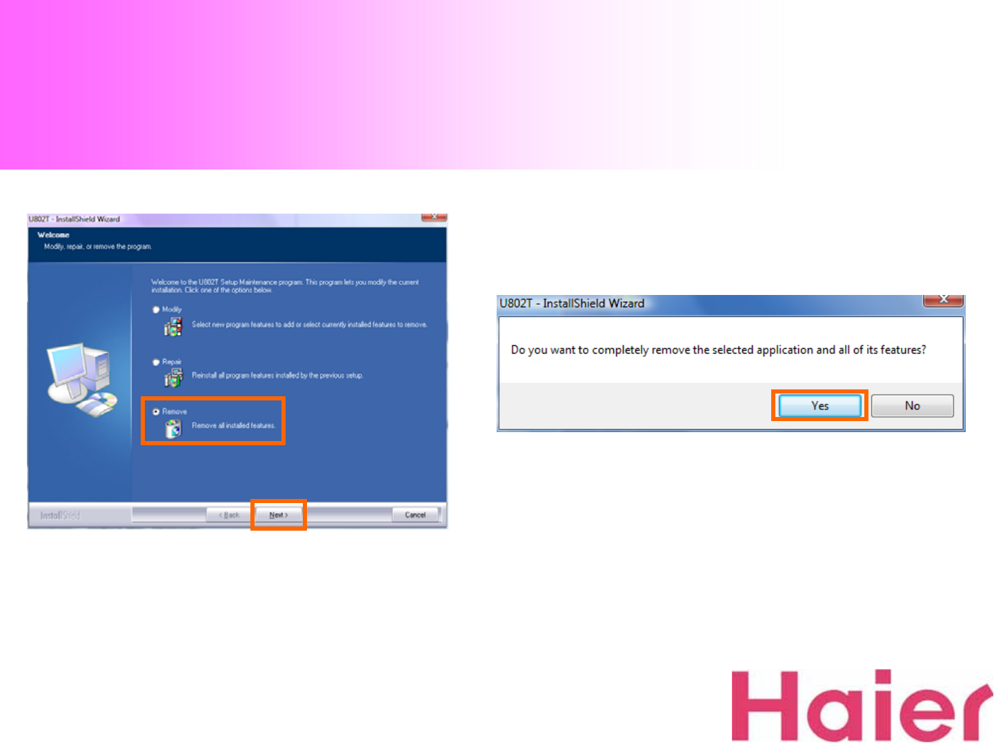
12. Un-Installation – Windows Vista
2. “My Computer” → “Program modify, repair or
remove the program”, Select the “Remove”
Then when the new pop-up is displayed, click to “Yes”
as like the Right Screen.
Note: It doesn’t require for U802T to be connected in USB port
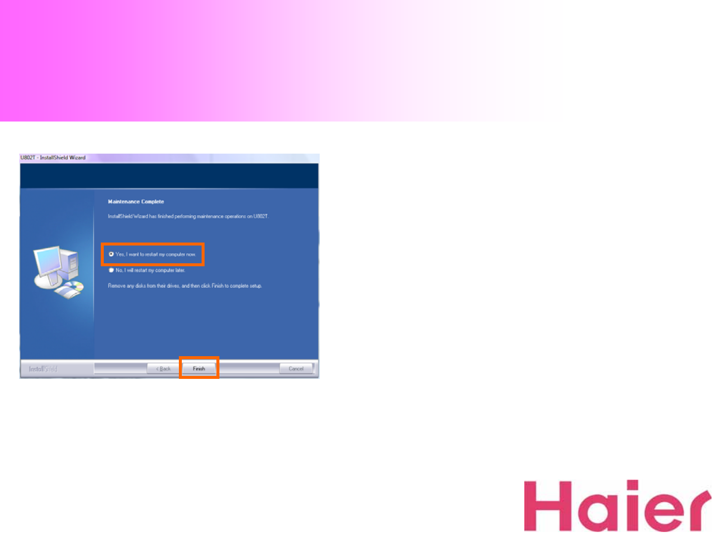
12. Un-Installation – Windows Vista
3. When you complete the Un-installation, Please
select “Yes, I want to restart my computer now” then
click “Finish”
Note: It doesn’t require for U802T to be connected in USB port

13. Health and safety Information
* Operating enviornment
Remember to follow any special regulations in force in the area you are in, and always turn off your modem whenever it
is forbidden to use it, or when it may cause interference or danger.
When connecting the modem to another device, do not connect incompatible products.
As with other mobile radio transmitting equipment, users are advised that for the satisfactory operation of the equipment
and for the safety of personnel, it is recommended that the equipment should only be used in the normal operating
position
* Electronic Devices
Most modern electronic equipment is shielded from radio frequency (RF) signals. However, certain electronic equipment
may not be shielded against the RF signals from your wireless modem. Consult the manufacturer to discuss alternatives.
Pacemakers
Pacemaker manufacturers recommend that a minimum distance of 15cm be maintained between a wireless device and a
pacemaker to avoid potential interference with the pacemaker.
These recommendations are consistent with the independent research and recommendations of Wireless Technology
Research. If you have any reason to suspect that interference is taking place, turn off your modem immediately.

13. Health and safety Information
Hearing aids
Some digital wireless devices may interfere with some hearing aids. In the event of such interference, you may wish to
consult your hearing aid manufacturer to discuss alternatives.
Other medical devices
If you use any other personal medical devices, consult the manufacturer of your device to determine if it is adequately
shielded from external RF energy.
Your physician may be able to assist you in obtaining this information
Turn off your modem in health care facilities when regulations posted in these areas instruct you to do so
Vehicles
RF signals may affect improperly installed or inadequately shielded electronic systems in motor vehicles. Check with the
manufacturer or its representative regarding your vehicle.
You should also consult the manufacturer of ant equipment that has been added to your vehicle.
* Care and maintenance
-Keep your modem and accessories out of the reach of small children and pet. They may accidentally damage these
things or choke on small parts
-Keep your modem dry. Precipitation, humidity, and liquids contain minerals that corrode electronic circuits.

13. Health and safety Information
-Do not drop, knock or shake the modem. Rough handling can break internal circuit boards.
-Do not store the modem in hot areas. High temperatures can shorten the life of electronic devices and warp or melt
certain plastics.
-Do not store the modem in cold areas. When the modem warms up to its normal operating temperature, moisture can
form inside the modem, which may damage the modem’s electronic circuit boards.
-Do not put the modem in or on heating devices, such as a microwave oven, stove, or radiator. The modem may
explode when overheated.

RF EXPOSURE INFORMATION
•Your USB Modem is a radio transmitter and receiver. It is designed and manufactured not to exceed the emission limits for exposure to
radio frequency (RF) energy set by the Federal Communications Commission of the U.S.Government. These limits are part of
comprehensive guidelines and establish permitted levels of RF energy for the general population. The guidelines are based on standards
that were developed by independent scientific organizations through periodic and thorough evaluate on of scientific studies. The
standards include a substantial safety margin designed to assure the safety of all persons, regardless of age and health.
• The exposure standard for wireless devices employs a unit of measurement known as the Specific Absorption Rate, or SAR. The SAR
limit set by the FCC is 1.6 W/kg.*Tests for SAR are conducted with the device transmitting at its highest certified power level in all tested
frequency bands. Although the SAR is determined at the highest certified power level, the actual SAR level of the device while operating
can be well below the maximum value. This is because the phone is designed to operate at multiple power levels so as to use onlythe
power required to reach the network. In general, the closer you are to a wireless base station antenna, the lower the power output. Before
a wireless device is available for sale to the public, it must be tested and certified to the FCC that it does not exceed the limit established
by the government adopted requirement for safe exposure.
• The highest SAR value for this CDMA Dongle is 0.376 W/kg (CDMA CELLULAR). The FCC has granted an Equipment Authorization for
this CDMA Dongle with all reported SAR levels evaluated as in compliance with the FCC RF exposure guidelines. SAR information on
this model phone is on file with the FCC and can be found under the Display Grant section of http://www.fcc.gov /oet / fcc id after
searching on FCC ID : SG7U802T.
• Additional information on Specific Absorption Rates (SAR) can be found on the Cellular Telecommunications &Internet Association (CTIA)
web-site at http://phonefacts.net.*In the United States and Canada, the SAR limit for mobile phones used by the public is 1.6watts/kg
(W/kg)averaged over one gram of tissue. The standard incorporates a substantial margin of safety to give additional protection for the
public and to account for any agitations in measurements.
• In August 1996 the Federal Communications Commission (FCC) of the United States with its action in Report and Order FCC 96-326
adopted an updated safety standard for human exposure to radio frequency (RF) electromagnetic energy emitted by FCC regulated
transmitters. Those guidelines are consistent with the safety standard previously set by both U.S. and international standards bodies. The
design of this phone complies with the FCC guidelines and these international standards.
• For more information about RF exposure, please visit the FCC website at www.fcc.gov

WARNING!
Read this information before use
•Caution
Modifications not expressly approved by the party responsible for compliance could void the user’s authority to
operate the equipment.
•FCC Compliance Information
This device complies with Part 15 of FCC Rules. Operation is subject to the following two conditions: (1) This
device may not cause harmful interference, and (2) This device must accept any interference received. Including
interference that may cause undesired operation.
•Information to User
This equipment has been tested and found to comply with the limits for a Class B digital device, pursuant to part
15 of the FCC Rules. These limits are designed to provide reasonable protection against harmful interference in a
residential installation. This equipment generates, uses and can radiate radio frequency energy and, if not installed
and used in accordance with the instructions, may cause harmful interference to radio communications. However,
there is no guarantee that interference will not occur in a particular installation. If this equipment does cause
harmful interference to radio or television reception, which can be determined by turning the equipment off and on,
the user is encouraged to try to correct the interference by one or more of the following measures:
- Reorient or relocate the receiving antenna.- Increase the separation between the equipment and receiver.
- Connect the equipment into an outlet on a circuit different from that to which the receiver is connected.
- Consult the dealer or an experienced radio/ tv technician for help.