Hanatech DCNPRO automotive handheld scantool User Manual User s Manual G
Hanatech Co.,Ltd automotive handheld scantool User s Manual G
UserManual.wiki
>
Hanatech
>
DCNPRO User Manual
users manual
Navigation menu
Upload a User Manual
Namespaces
Wiki Guide
HTML
PDF
Info
Views
User Manual
Discussion / Help
Navigation
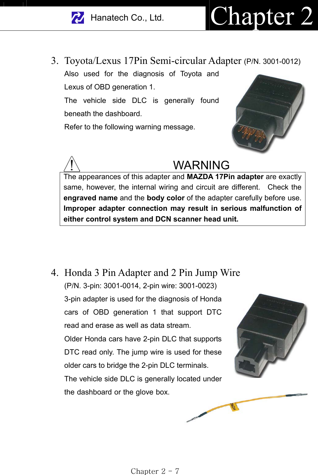
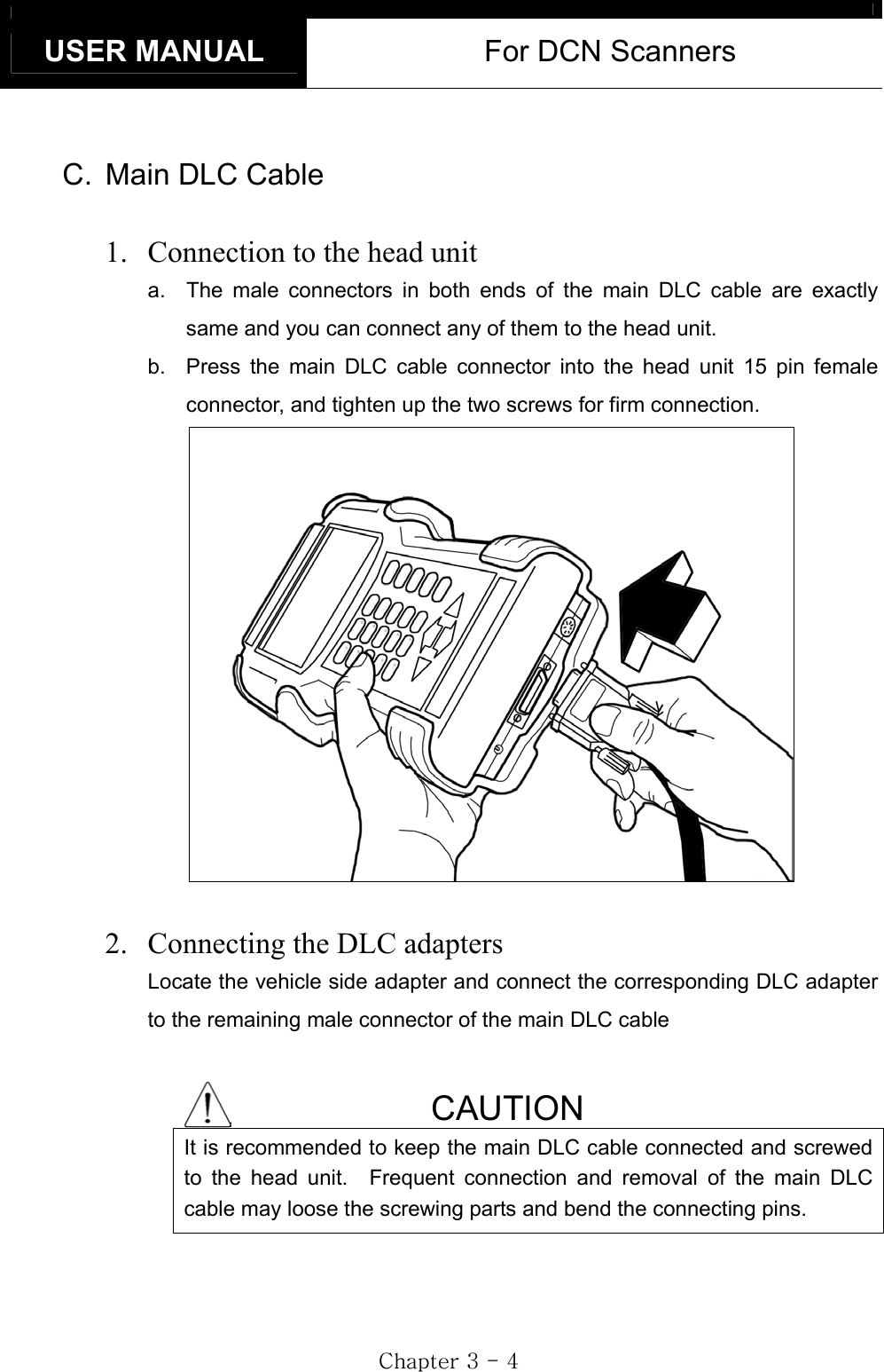
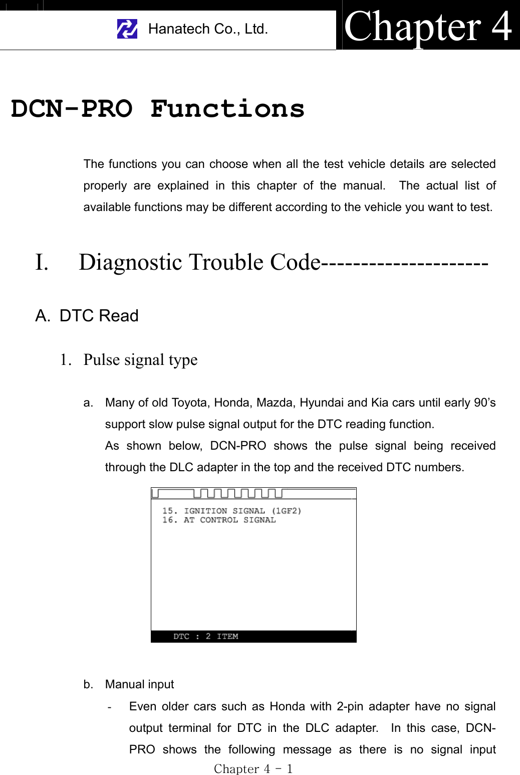
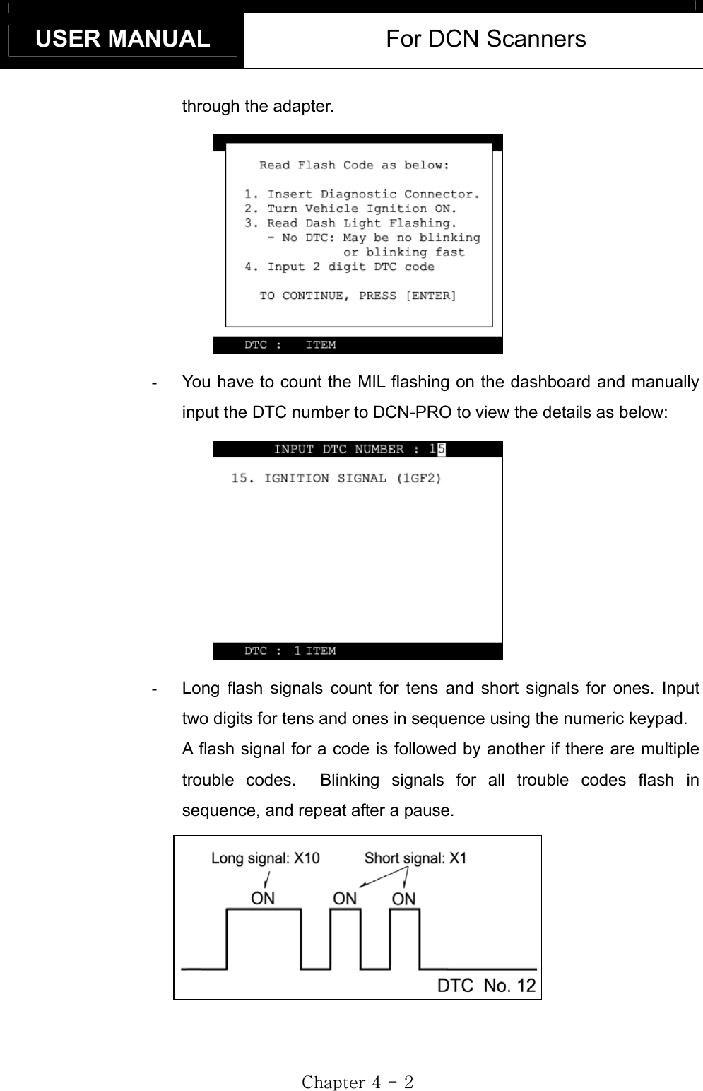
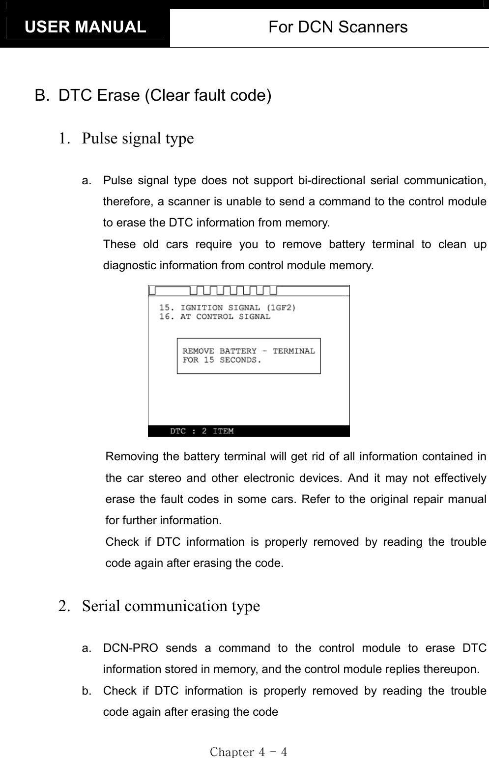
![USER MANUAL For DCN Scanners GjGXGTG]GGIII. WARRANTY SERVICE ------------------------- Warranty PeriodIn principle, DCN products are warranted to the consumer to be free of defects in material and workmanship for the period of 3 years after the date of purchase. If the product is found defective during this period, the product can be returned to Hana Tech and will be repaired or replaced free of charge. Freight and repair Cost For the repair of head unit, Hana Tech covers the freight cost for the service during one year from the date of purchase, and you can send the troubled unit to your local distributor without having to pay the freight cost. You should consult with your local distributor about the validity of remaining warranty period before sending the unit. For the remaining two years, you are liable for any international cost incurred. Repair or replacement will be provided free of charge. When the warranty period is expired after three years, the customer must pay the round trip freight and the repair or replacement cost. Upon delivery Hana Tech inspects all the ordered product parts and components are included in the package before shipment, and includes the original copy of pre-shipment inspection report in the box. As soon as the product is delivered to you, please ensure everything you ordered is properly checked and included referring to the pre-shipment inspection report. If there is anything missing or damaged, you must notify the local distributor immediately within 3 working days from the delivery date for free of charge replacement of the parts. In case of trouble If you encounter any malfunction or trouble with the equipment, please refer to the Trouble Shooting chapter in this manual. If the problem cannot be solved, please contact your local distributor for assistance. For early identification of a fault or error,](https://usermanual.wiki/Hanatech/DCNPRO/User-Guide-426040-Page-9.png)
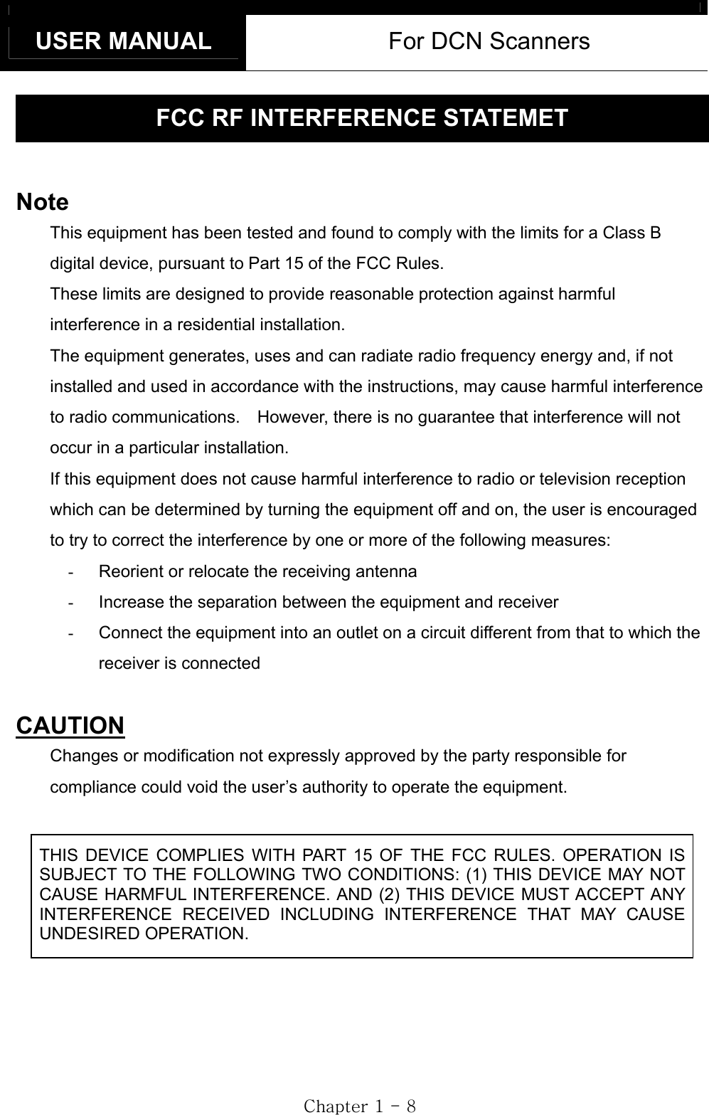
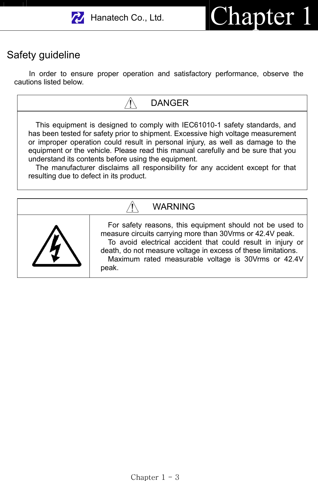
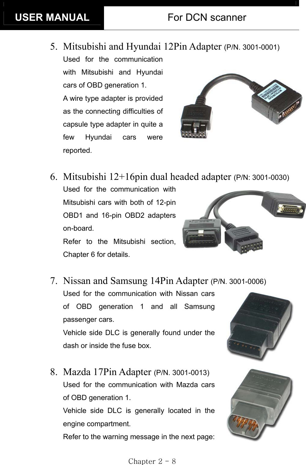
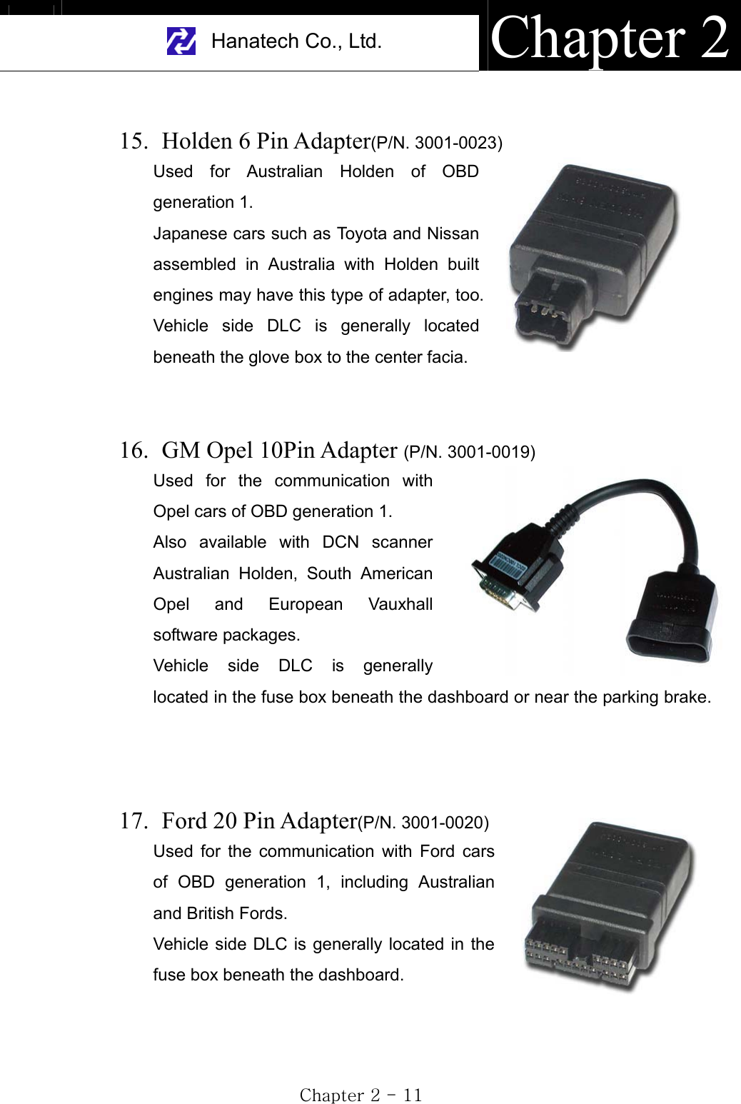
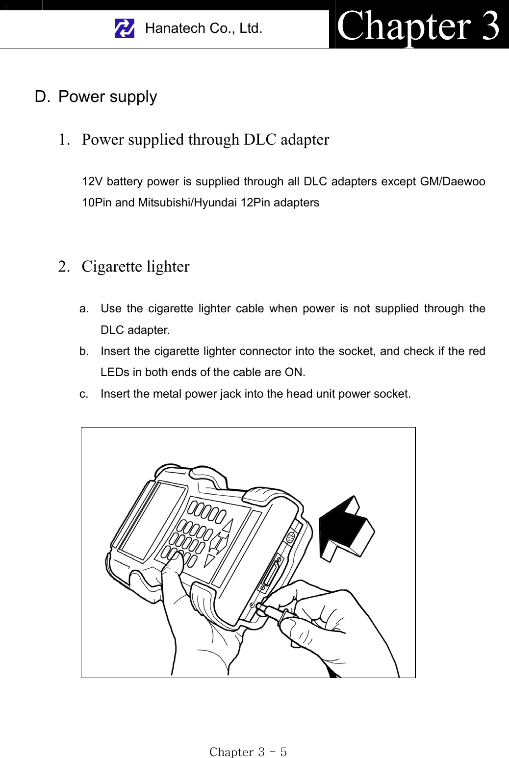
![USER MANUAL For DCN scanner GjGYGTG]GB. Diagnostic Adapters Diagnostic adapters are sold separately, therefore check if all the adapters you ordered are included in the package upon delivery. There are two types of adapters: capsulated and wired types. Most of DCN scanner DLC adapters are capsulated for better durability and storage, however, sometimes it is difficult or almost impossible to connect the capsulated adapter to vehicle side DLC when it is located deep inside beneath the dashboard. We use wire type adapters for the cars such as Hyundai and Kia that we were reported to have such connecting difficulties. Capsule type Wire type 1. OBD2 Standard Adapter (P/N. 3001-0010)Used for all OBD generation 2 and EOBD compatible vehicles. Vehicle side DLC is generally located near the driver’s seat and most frequently found beneath the dash panel. 2. Toyota / Lexus 17Pin Rectangular Adapter (P/N. 3001-0011)Used for the diagnosis of Toyota and Lexus of OBD generation 1. Vehicle side DLC of this type is generally located in the engine compartment.](https://usermanual.wiki/Hanatech/DCNPRO/User-Guide-426040-Page-18.png)
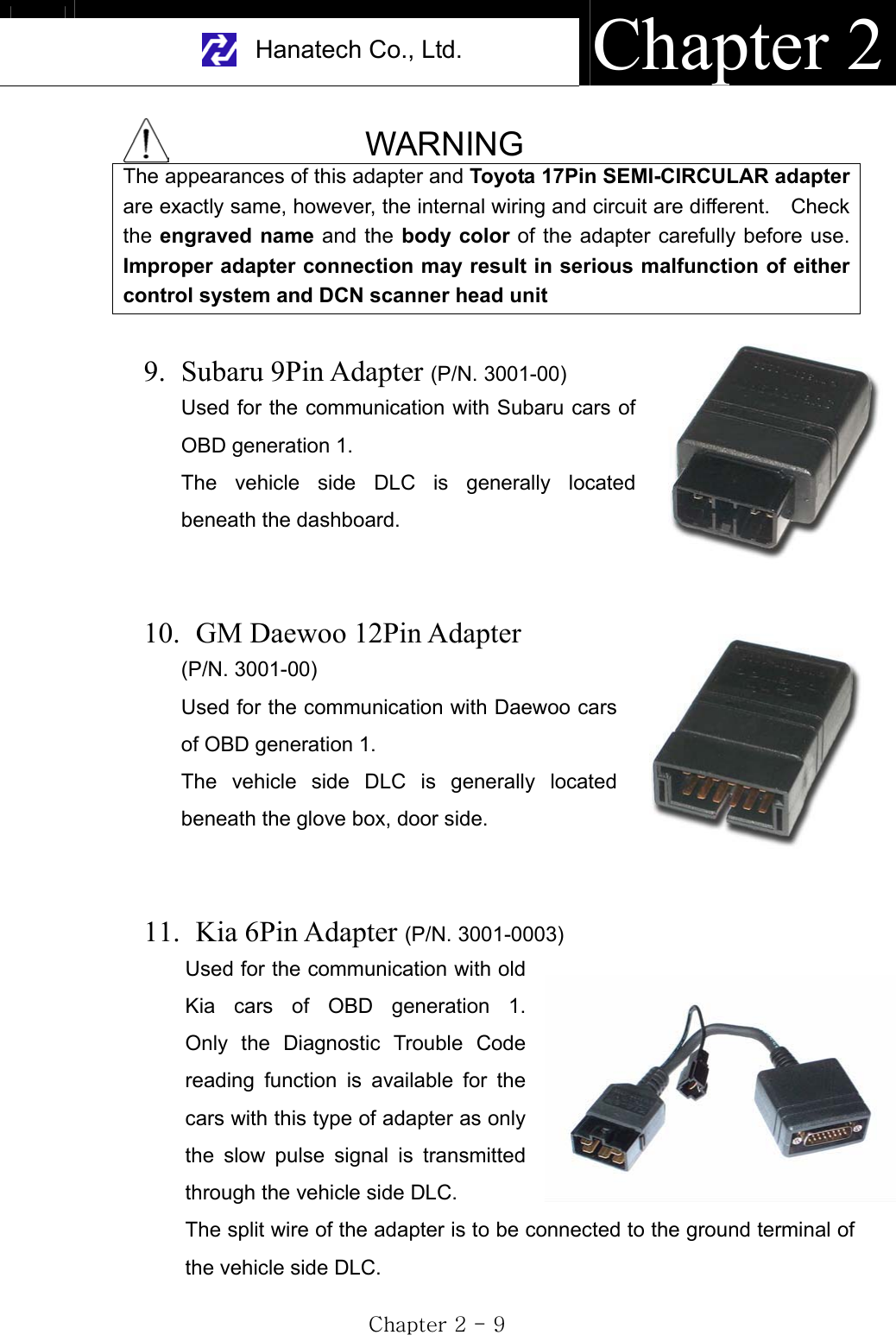
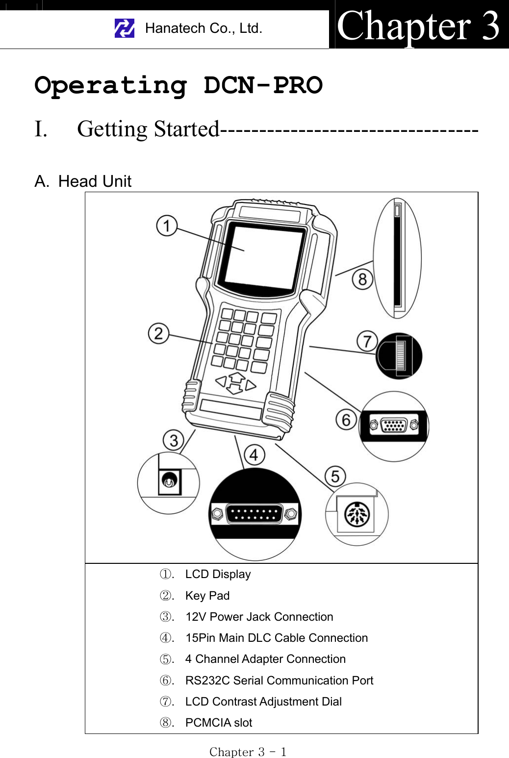
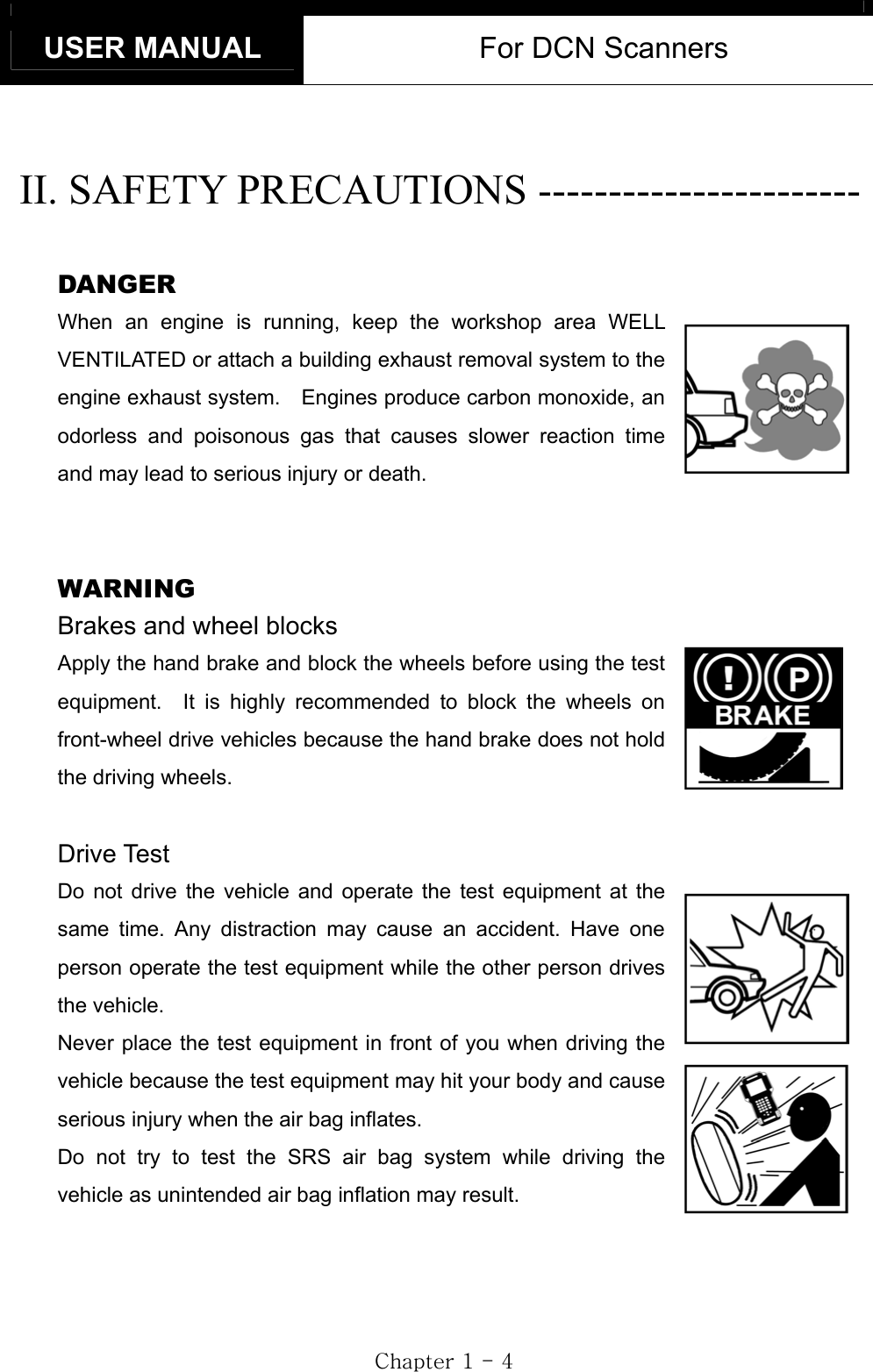
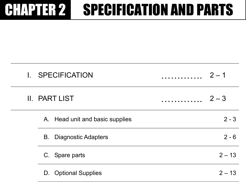
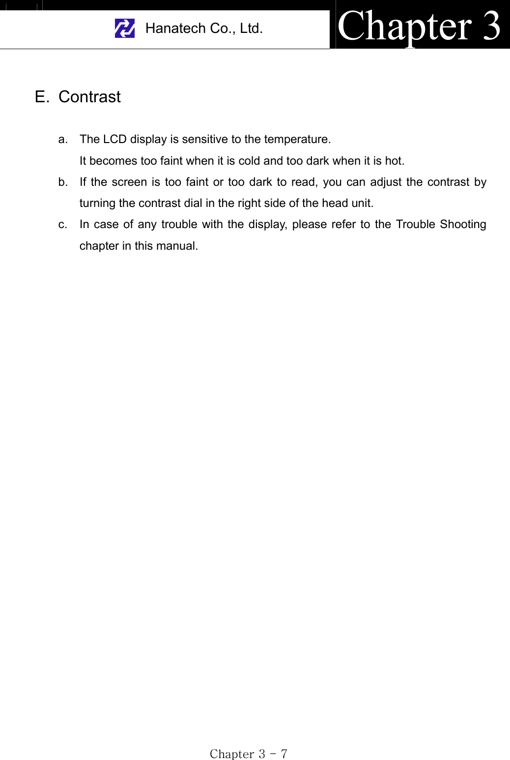
![USER MANUAL For DCN Scanners GjGZGTG]G3. Vehicle battery a. Since the head unit must be placed in the engine compartment when using multimeter, oscilloscope or ignition pattern analysis function, it is necessary to get the power from the vehicle battery. b. Connect the alligator clips of the battery power cable to the battery terminals of correct polarity. Check the red LED on the round socket turns ON. c. Connect the cigarette lighter power cable connector into the battery power cable socket. 4. Power ON Press the [POWER] key of the head unit key pad to turn power ON. To turn power OFF, press the [POWER] key for more than 1 second.](https://usermanual.wiki/Hanatech/DCNPRO/User-Guide-426040-Page-33.png)
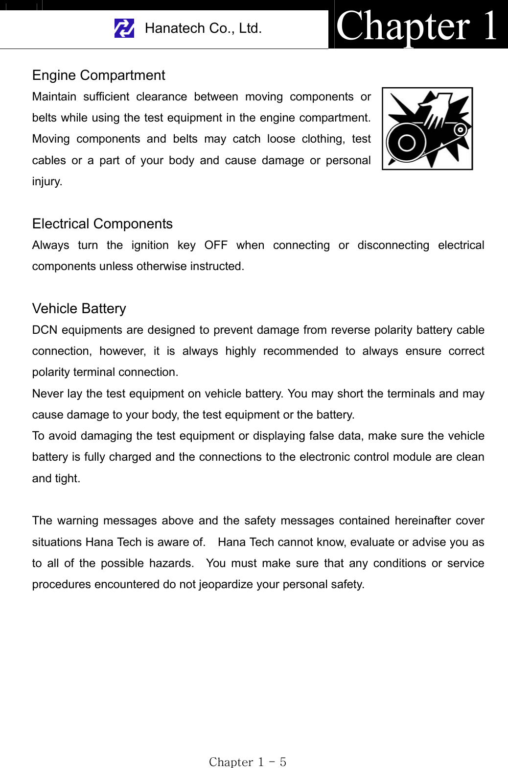
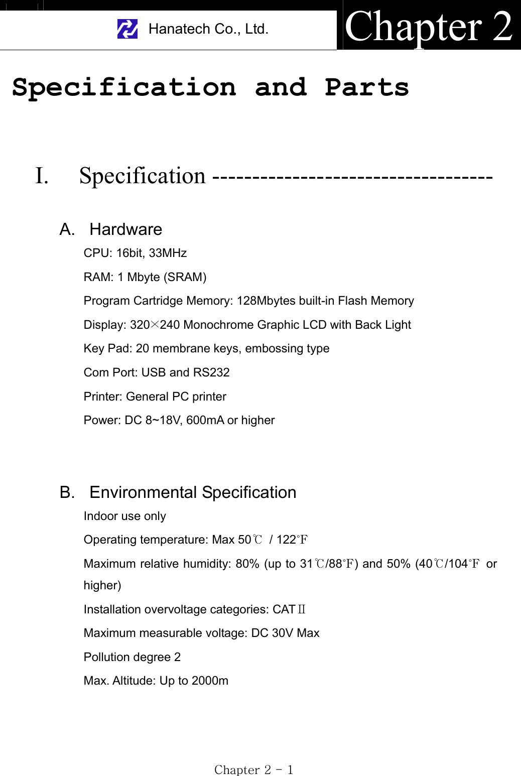
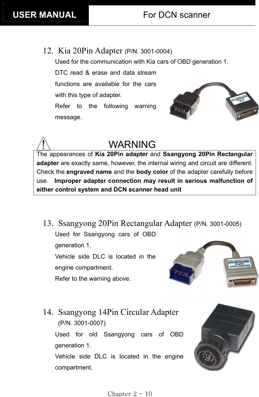
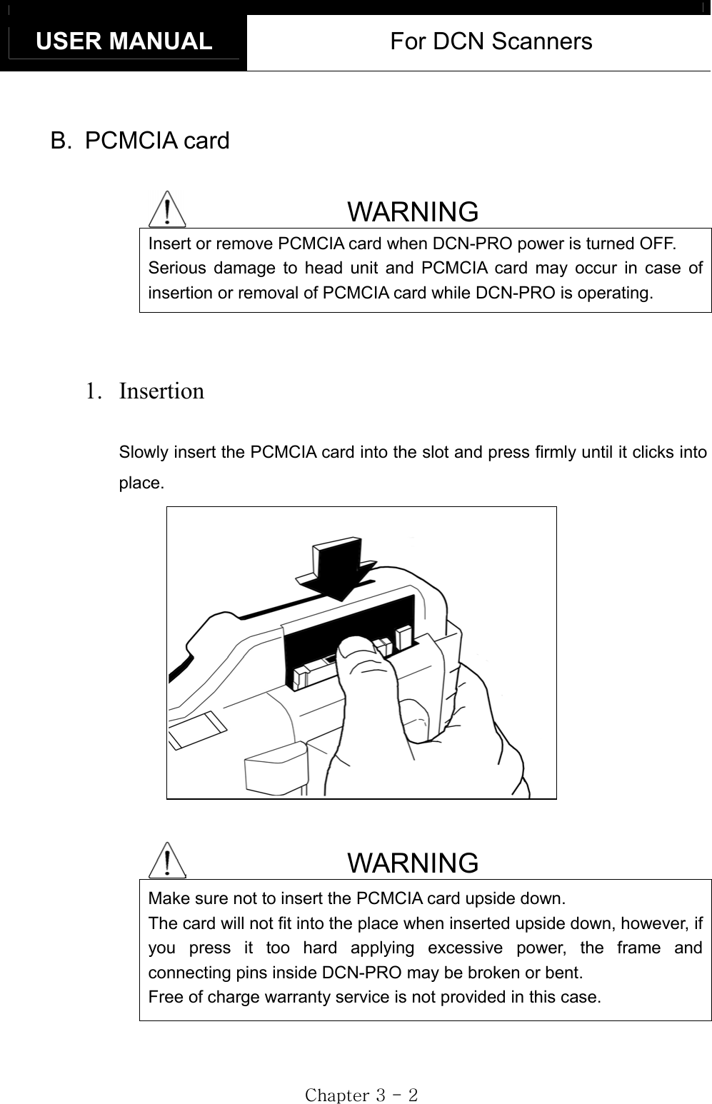
![USER MANUAL For DCN Scanners GjGZGTG_GII. Control Keys ----------------------------------- A. Keypad The keypad is made of chemistry proofing PVC material that prevents contamination and damage from hazardous oily workshop environment. The membrane keypad is designed and tested to maintain its normal operation over 1 million time key press for each. Each key is raised for better tactile feel. The keypad has total of 24 keys. B. Making selection in the menu 1. Numeric Keypad a. Simply press the corresponding number b. This is available only when you are selecting an item of which number is 9 or less. For more than 10, you should locate the highlighted bar on the desired item and press the [ENTER] key.](https://usermanual.wiki/Hanatech/DCNPRO/User-Guide-426040-Page-35.png)
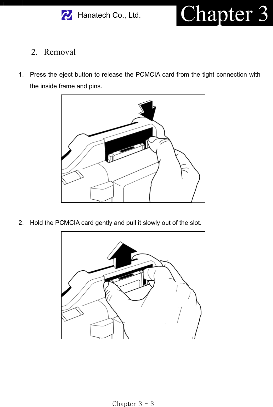
![Hanatech Co., Ltd. Chapter 3GjGZGTG`G2. Arrow keys ൖ ൘ Page Up/Down Scroll Up/ Down a. Scroll up and down the highlighted bar in the menu by pressing Up/Down arrow keys and press the [ENTER] key to confirm the selection. b. If the menu has more than 12 items, you may have to scroll up or down the pages to make selection. You do not have to pound on Up/Down arrow keys to scroll the whole page. Simply pressing the Left or Right arrow key will shift page to page. Move the highlighted bar by pressing the up/down keys when the desired item appears on the screen, and press the [ENTER] key. C. Function keys 1. POWER a. After connecting appropriate power cable, press this key shortly to turn the DCN-PRO on. b. To turn off, press this key for more than a second until the powering OFF message appears on the screen as shown in the right.](https://usermanual.wiki/Hanatech/DCNPRO/User-Guide-426040-Page-36.png)
![USER MANUAL For DCN Scanners GjGZGTGXWG2. Back light [ ] a. LCD module of DCN-PRO has an illuminating back panel for better legibility in dark or shady places. b. Press this button to turn the back light ON and OFF. 3. ESC Used to abort an operation of DCN-PRO or move to the upper level menu.4. HELP a. DTC Read -When a trouble code is detected, you can press this key to view the detailed information of the DTC. -DTC definition, DTC registration conditions and check points are provided (For Korean and Malaysian cars only as of May, 2003)b. Service Data (Data Stream) -While live data is being displayed on the screen, select a live data item by moving the highlighted bar, and press this key to view the detailed information about the selected item. -Standard value and technical explanations are provided. (For Korean and Malaysian cars only as of May, 2003)5. PRINT a. When a printer is connected to DCN-PRO via printer cable, press this key to print out the current display: DTC list, a set of data stream, oscilloscope waveform or ignition pattern. b. Refer to the Optional Parts section for detailed information on the printer cable.](https://usermanual.wiki/Hanatech/DCNPRO/User-Guide-426040-Page-37.png)
![Hanatech Co., Ltd. Chapter 3GjGZGTGXXGIII. Configuration ---------------------------------- Press the [6] key from the initial function menu to proceed to the configuration menu. You can check the version numbers of the software packages contained in the PCMCIA card, test the keypad and LCD, set up sound and language options and download software updates in the configuration menu. A. Software Information When you select [1. SOFTWARE INFORMATION] in the configuration menu, a list of software packages contained in the PCMCIA card will appear as below: Should you get any update files from your local distributor or from Hana Tech website, please compare the version number and last update date to check if the update is necessary.](https://usermanual.wiki/Hanatech/DCNPRO/User-Guide-426040-Page-38.png)
![USER MANUAL For DCN Scanners GjGZGTGXYGB. System Test You can test the proper operation of keypad and LCD display. 1. Keypad test -A test screen will appear as below when you select [1. Keypad Test] from the menu. -Press each key of the keypad and check if the color of the corresponding key on the screen turns inverted. Following is an example when the [ENTER] key is pressed. -Press the [ESC] key three times to abort the test.](https://usermanual.wiki/Hanatech/DCNPRO/User-Guide-426040-Page-39.png)
![Hanatech Co., Ltd. Chapter 3GjGZGTGXZG2. LCD test -Checks the LCD screen for any defective display. When [2. LCD TEST] is selected, HANA TECH logo appears and you will see the display gradates black and white in and outward as shown below: -Should you see any dot, line or blank pixel, please contact your local distributor/. C. Special functions 1. Download software -You can download the software updates from your PC when you select [1. DOWNLOAD SOFTWARE]. -Instructions will be given separately whenever an update is available. Contact your local distributor for the availability of update frequently and keep posted of such events.](https://usermanual.wiki/Hanatech/DCNPRO/User-Guide-426040-Page-40.png)
![USER MANUAL For DCN Scanners GjGZGTGX[G2. Language -You can select provided language. English and Spanish languages are available for selection as of May, 2003. -Hana Tech is translating the menu and messages of DCN-PRO to various local languages such as Russian, Arabic and Chinese for convenience of non-English speaking customers, and the each language will be provided as an update when the translation is completed. 3. Sound -You can toggle ON and OFF the key sound. 4. Save Configuration -If you have made any change in this [Special Function] menu, you have to save the configuration to make such changes effective. -Press the [4] key to save the changes in configuration](https://usermanual.wiki/Hanatech/DCNPRO/User-Guide-426040-Page-41.png)
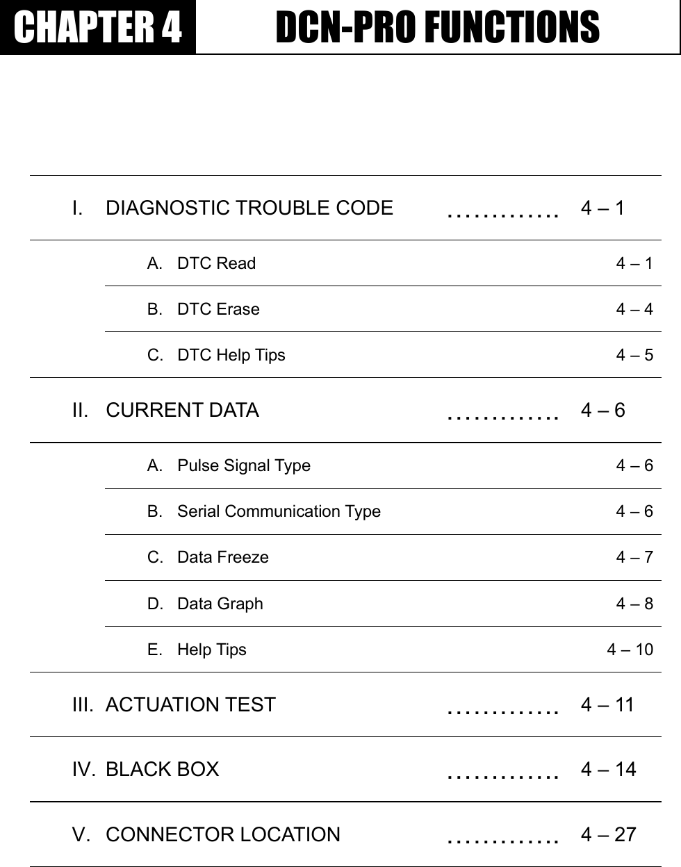
![Hanatech Co., Ltd. Chapter 4GjG[GTG\GC. DTC Help tips a. Help tips are provided when you press the [HELP] key after locating the highlighted bar on one of the detected trouble code(s). This function is available when DCN-PRO detects one or more trouble code(s) b. Help tips including trouble code definition, conditions and check points are provided for all Korean cars and Malaysian cars as of May 2003. Wiring diagrams are also provided for Korean cars of 2000 model-year or older. c. Press the [ESC] key to return to DTC list.](https://usermanual.wiki/Hanatech/DCNPRO/User-Guide-426040-Page-47.png)
![USER MANUAL For DCN Scanners GjG[GTG]GII. Current Data ----------------------------------- (= Data Stream, Live Data, Service Data)A. Pulse Signal Type a. Data stream is not generally supported for this type of old cars because the speed of pulse signal communication is too slow to read the data stream variables. b. Some of old Toyota cars using 17-pin rectangular adapter exceptionally support data readings as the system supports relatively high speed pulse signal communication. B. Serial Communication Type a. Most of control systems with serial communication support data stream function. Select [Current data] from the menu, then the data readings follow. b. Some systems like SRS or ABS may be designed not to support data stream intentionally by the car make while the other systems are supported. A scanner is a passive tool that reads information from the control system, and it is unable to actively generate information that the system does not provide.](https://usermanual.wiki/Hanatech/DCNPRO/User-Guide-426040-Page-48.png)
![Hanatech Co., Ltd. Chapter 4GjG[GTG^GC. Data Freeze The [Data Freeze] function places the selected data stream variable on top of the LCD screen so that the user can check and compare desired sensor values continually without having to scroll up and down. This function is different from ‘Freeze Frame Data’ function of Generic OBD2. 1) Step One Select a desired sensor using the [ൖ][൘] and the [][] keys. 2) Step Two Press the [ENTER] key to freeze the selected sensor. i.e., when O2 sensor and MAP sensor are selected and frozen, these sensor values will be placed at the top of the display as below : 3) Step ThreeUp to five sensors may be frozen at a time. For example, if the Injection Time, which can be shown when scrolled down, is selected and frozen, Injection Time value will be placed below the previously frozen O2 and MAP sensor.](https://usermanual.wiki/Hanatech/DCNPRO/User-Guide-426040-Page-49.png)
![USER MANUAL For DCN Scanners GjG[GTG_GD. Data Graph DCN PRO provides the [Data Graph] function for more efficient data analysis. a When you press the [1] key after locating the highlight bar on the desired sensor, the sensor data graph will be displayed as shown below. b You can display up to 3 graphs in a screen by choosing the sensors as previously explained [Data Freeze] procedure - Press the [Enter] key after locating the highlight bar on the desired sensor, and then press the [1] key. When more than 4 sensors are selected, the graphs of upper three sensors will be displayed.](https://usermanual.wiki/Hanatech/DCNPRO/User-Guide-426040-Page-50.png)
![Hanatech Co., Ltd. Chapter 4GjG[GTG`Gc For each sensor data graph, the name of the sensor and its current value will be simultaneously displayed together. d To change the sensor, go back to the previous Service Data display by pressing the [Esc] key, and then choose other sensors. e To halt the graph output, press the [ENTER] key. It will resume when you press the [ENTER] key again.](https://usermanual.wiki/Hanatech/DCNPRO/User-Guide-426040-Page-51.png)
![USER MANUAL For DCN Scanners GjG[GTGXWGE. Help tips a When you press the [HELP] key after locating the highlight bar on a certain data stream variable, the help message will be displayed. This works the same for detected Trouble Codes in [Self Diagnosis] function. b Detailed information including conditional standard range on the selected sensor will be displayed as shown below. c Press the [ESC] key to go back to the data stream display.](https://usermanual.wiki/Hanatech/DCNPRO/User-Guide-426040-Page-52.png)
![USER MANUAL For DCN Scanners GjG[GTGXYGA. Menu Selectiona Choose [ACTUATION TEST] from the function Selection Menu b The name of the actuator to be tested, test method and the test condition are shown in the display. Available actuators, test methods and conditions may differ in each vehicle. B. Test Start 1. Selecting Test Item a Choose an actuator to test from the menu by using the [] and [] keys. b Check the test conditions and press the [ENTER] key when all the conditions are met. 2. Testing a [TESTING...] message will be displayed during the actuation test Test method means how the actuation test will be performed. Check the actual reaction of the actuator](https://usermanual.wiki/Hanatech/DCNPRO/User-Guide-426040-Page-54.png)
![Hanatech Co., Ltd. Chapter 4GjG[GTGXZGb In the example below, the injector will stop injecting fuel for 6 seconds while engine is idling, and it will make engine stall or unstable. c Testing a fan or an injector is easy to check the proper reaction as it generates distinctive changes in vehicle condition such as fan whining or unstable idling. However, valves or motors are generally tested while engine is stopped and all you can hear may be a small and unclear electric buzzing sound. Test in a quite place and observe the test results carefully. d When the test is completed, the [TEST COMPLETE] message will be displayed. You can choose other actuators by using the [] and []keys. Press the [ESC] key to quit test mode.](https://usermanual.wiki/Hanatech/DCNPRO/User-Guide-426040-Page-55.png)
![USER MANUAL For DCN Scanners GjG[GTGX[GٻIV. Black Box -------------------------------------- Just like the 'Black Box' or a ‘flight recorder’ of an aircraft, DCN-PRO can 'record' data stream during the vehicle drive test and the recorded data can be 'retrieved' later for intensive analysis of vehicle's condition. A. Function selection Choose [#. Black Box Data] from the [Function Selection Menu] after selecting Origin, Car Manufacturer, Model name and system to test.](https://usermanual.wiki/Hanatech/DCNPRO/User-Guide-426040-Page-56.png)
![Hanatech Co., Ltd. Chapter 4GjG[GTGX\GB. Capacity a During a normal test, the [Data Stream] frames pass by in rapid succession, and cannot be recalled unless the data has been saved. Thanks to its extensive internal memory, DCN-PRO can record up to 2040 frames of Data Stream for multiple cars. b By loading the recorded data, you can diagnose sensor data frame to frame without missing a single critical moment. C. Memory Checka. DCN-PRO checks its internal memory before it starts recording Black Box data. If there is no sufficient free memory space available, DCN-PRO will suggest deleting one or more of previous record(s). b. Press the [ERASE] key to proceed, then a list of saved data will follow. Locate the highlight bar on data to delete, and press the [ENTER] key. A query for your confirmation will follow. Press the [YES] key to erase otherwise press the [NO] key.](https://usermanual.wiki/Hanatech/DCNPRO/User-Guide-426040-Page-57.png)
![USER MANUAL For DCN Scanners GjG[GTGX]GD. PID(Live data parameter) selection a You are required to select the parameters to record. b DCN-PRO will show you the whole live data parameters available in the control system you selected. Locate the highlight bar on the desired parameter and press the [ENTER] key. Selected parameter will be marked star(*). You can also deselect the parameter by repeating the procedure. c You can select up to 40 PIDs to record. Press the [ESC] key when the selection is completed, then DCN-PRO will start recording data.](https://usermanual.wiki/Hanatech/DCNPRO/User-Guide-426040-Page-58.png)
![Hanatech Co., Ltd. Chapter 4GjG[GTGX^GE. Trigger Modes There are three trigger modes in the black box function. a Continuous Record Mode (No trigger mode) -DCN-PRO will record live data of selected parameters up to 2040 frames or until you press the [ESC] key. -Percentile memory usage and sampling time(frequency) will appear in the center of the screen while recording data, and the actual live data values will remain unchanged. -Since no DTC trigger is applied in this mode, number of “Before DTC” frames will remain 0, and the “After DTC” will keep increasing as the more frames are recorded.](https://usermanual.wiki/Hanatech/DCNPRO/User-Guide-426040-Page-59.png)
![USER MANUAL For DCN Scanners GjG[GTGX_Gb Automatic Trigger Mode (Triggered by DTC) -DCN-PRO will keep recording live data of selected parameters up to 128 frames. -Once a DTC is detected or the [ESC] key is pressed by the user, it will proceed with recording remaining frames up to 2,040 or until you abort. -This function will let you have a set of data stream before and after the ECM’s DTC recognition when you perform the test drive. -Before DTC, you will see the Live Data of the selected parameters keep refreshing, however, once triggered by DTC or [ESC] key stroke, only the percentile process information and sampling frequency will be displayed.](https://usermanual.wiki/Hanatech/DCNPRO/User-Guide-426040-Page-60.png)
![Hanatech Co., Ltd. Chapter 4GjG[GTGX`Gc Manual Trigger Mode -DCN-PRO will keep recording live data of selected parameters up to 128 frames, and once the [ESC] key is pressed by the user, it will proceed with recording remaining frames up to 2040. -The screen display is the same as when selecting the Auto Trigger Mode.](https://usermanual.wiki/Hanatech/DCNPRO/User-Guide-426040-Page-61.png)
![USER MANUAL For DCN Scanners GjG[GTGYWGF. Saving the recorded data a When the total frame number reaches 2040 or when you press the [ESC] key to abort, a query asking you if you would like to save recorded data or to discard it. Press [YES] to save or [NO] to cancel. b When pressed [YES], a dialog box follows and asks you to input the test date. Enter the date and press the [ENTER] key to save the recorded data to DCN-PRO memory. Pressing the [ESC] key cancels saving data. Date format is DD-MM-YYYY(D-day, M-month, Y-year), and only numeric values are available. c Tested Vehicle model name and control system will be saved as well as the date stamp for future retrieval.](https://usermanual.wiki/Hanatech/DCNPRO/User-Guide-426040-Page-62.png)
![Hanatech Co., Ltd. Chapter 4GjG[GTGYXGG. Black Box Data Load a You can load saved data by choosing [BLACKBOX RECORD LOAD / ERASE] from the [Car Manufacturer Selection] menu as shown below: b A list of recorded Black Box Data will follow for your selection Up to 4 back box data can be stored in the memory per car manufacturer, therefore, up to 4 saved black box data can be listed in the menu. c The details of recorded data will be displayed for confirmation. If the record is correct, press the [ENTER] key. Press the [ESC] key to abort. d If you want to erase any of these saved data, locate the highlight bar and press the erase key.](https://usermanual.wiki/Hanatech/DCNPRO/User-Guide-426040-Page-63.png)
![USER MANUAL For DCN Scanners GjG[GTGYYGH. Loaded Blackbox data Loaded black box data has basically the same format as the [Service Data (Live Data Stream)]. See the illustration below. 1. Data format In the lower part of the display, the total number of recorded frames, frame number before and after the DTC(Diagnostic Trouble Code), and the number of DTC detected is displayed. In the example below, you can see that a total of 458 frames were recorded, and data stream currently shown in the main window is of the 336th frame from the beginning. It also tells you that the current frame is the 80th after 2 trouble codes were detected. The live data values may not be realistic as the screen was captured while the scan tool was linked to a simulator. 2. Data Replay a. Press the [YES] key then the saved blackbox data will start replying DCN-PRO preserves the refresh time intervals of Black Box data. Therefore, Black Box data is replayed at the same speed as when it was originally recorded.](https://usermanual.wiki/Hanatech/DCNPRO/User-Guide-426040-Page-64.png)
![Hanatech Co., Ltd. Chapter 4GjG[GTGYZGb. If you want to go forward or backward faster, press the [ൖ] or [൘]key while replaying. Replay speed will restore to the original speed when the key is released. c. Pressing the [YES] key will pause the replay. You can resume replaying from the frame where it was paused by pressing the [YES] key again. d. Pressing the [NO] key will stop replaying. You can restart replay by pressing the [YES] key again, but it will start from the first frame.](https://usermanual.wiki/Hanatech/DCNPRO/User-Guide-426040-Page-65.png)
![USER MANUAL For DCN Scanners GjG[GTGY[G3. Graph a As previously explained in section [3. Service Data], data from up to three selected parameter data can be graphed. b Make sure that the Black Box data replay is stopped. If it is being replayed or paused, press the [NO] key to stop replaying completely. c Choose the parameter by locating the highlight bar and pressing the [ENTER] key. The selected parameter will be marked with a triangle as shown below: d Then press the [1] key to view the data in graph format. The line graphs are flat as it is not based on data recorded from the active vehicle.](https://usermanual.wiki/Hanatech/DCNPRO/User-Guide-426040-Page-66.png)
![Hanatech Co., Ltd. Chapter 4GjG[GTGY\Ge Up to 316 frames can be displayed on a single page. If recorded data has more than 316 frames, you can shift to next or previous page by using the [] and [] keys. f The dotted line indicates from which frame the live data parameter values are being displayed. You can move it left and right with the [ൖ]and [൘] keys. g Elapsed time and frame number are indicated in the bottom. -Continuous Record (No trigger) Mode: Elapsed time and number of frames from the first frame -Automatic / Manual Trigger (Triggered by DTC or user) Mode:Elapsed time and number of frames from the trigger point (DTC detection or [ESC] key stroke by the user). Before the trigger point will be marked in negative values. h To return to the Black Box Data Display, press the [ESC] key.](https://usermanual.wiki/Hanatech/DCNPRO/User-Guide-426040-Page-67.png)
![USER MANUAL For DCN Scanners GjG[GTGY]G4. DTC a You can check the DTC(s) found during recording Black Box Data. b Make sure that the Black Box data replay is stopped. If it is being replayed or paused, press the [NO] key to stop replaying completely. c Press the [2] key then the list of DTC(s) will appear as below: d Because Black Box Data is not live or active, you cannot erase DTC(s).](https://usermanual.wiki/Hanatech/DCNPRO/User-Guide-426040-Page-68.png)
![Hanatech Co., Ltd. Chapter 4GjG[GTGY^GV. Connector Location --------------------------- a The vehicle side OBD2 adapter is easy to find as the location is quite regular – under the dash, however, the old vehicle side DLC adapters of OBD generation 1 are located quite randomly and sometimes it is very difficult to find. DCN-PRO has the vehicle side adapter location maps for each car make to aid the user in locating the adapters. The locations suggested in this function are purely from HANA TECH’s experience, therefore, it may contain incorrect information. It is always highly recommended to refer to the original repair manual published by the car manufacturers for correct information. Gb Select [CONNECTOR LOCATION] from the vehicle selection menu if the adapter is not found in the place where it is supposed to be. A drawing indicating the location of the vehicle side adapter follows. In the right bottom of the display, the total number of location maps for the selected car make is indicated. The example below is when Hyundai motors is selected, and it tells there are total 5 maps.](https://usermanual.wiki/Hanatech/DCNPRO/User-Guide-426040-Page-69.png)
![USER MANUAL For DCN Scanners GjG[GTGY_Gc The maps are provided in the order of most frequently found location. Press Up or Down key to view the next or previous map. Press the [ESC] key to return to vehicle selection menu. d Location maps for Korean cars are based on Left Hand Drive vehicles, and the others such as Japanese, Australian and Malaysian cars are based on Right Hand Drive cars. You may have to consider reversed image according to your local practice. Refer to each car make section in this manual for further information.](https://usermanual.wiki/Hanatech/DCNPRO/User-Guide-426040-Page-70.png)