Hanchett Entry Systems K200 RFID Cabinet Lock User Manual 3085006 001 Rev A 031215
Hanchett Entry Systems, Inc. RFID Cabinet Lock 3085006 001 Rev A 031215
UserManual.wiki
>
Hanchett Entry Systems
>
K200 User Manual
user manual
Navigation menu
Upload a User Manual
Namespaces
Wiki Guide
HTML
PDF
Info
Views
User Manual
Discussion / Help
Navigation

![Part Number 3085006.001, Rev. A 5 2. TRANSFER the location of the inside wall of the cabinet to the door. a. MEASURE the horizontal distance between the inside edge of the cabinet and the door edge. NOTE: The drawn line depicts the location of the strike mounting surface. b. LOCATE the lock centerline notch on the latch and MARK this point on the inside of the cabinet door using a pencil. c. DRAW the horizontal latch centerline from this mark on the inside of the cabinet door and TRANSFER it to the outside of the cabinet door. 3. PLACE and USE the Lock/Reader Template. NOTE: The orientation will be reversed for a right hand door. a. CUT through line to separate the Strike Plate Template. b. PEEL OFF the protective layer of the Lock Template, ALIGN it to both the latch centerline and the line depicting the inside wall of cabinet, and PRESS to secure. NOTE: Two of the holes in the following step are 3/16” [4.76 mm] diameter and two are 1/2” [12.70 mm] diameter. The two pilot holes are 1/16” [1.59 mm]. c. DRILL four holes and two pilot holes through the cabinet, as shown in the figure below. d. DRILL only one 3/16” [4.76 mm] hole, depending on the desired Antenna/Reader orientation. e. IF the optional key override will be installed, THEN GO TO Step 5. f. REMOVE the lock template from the door.](https://usermanual.wiki/Hanchett-Entry-Systems/K200/User-Guide-2607277-Page-5.png)
![Part Number 3085006.001, Rev. A 6 4. INSTALL the shaft extension. a. IF the cabinet door thickness is greater than ½” [12.70 mm] (see Table 1), THEN INSTALL the Shaft Extension to the Antenna/Reader to ensure proper engagement into the lock. b. INSTALL the Shaft Extension to the shaft as shown in the figure, and firmly TIGHTEN the screw. Table 1 Door Thickness Extension Shaft Used? 1/16” [1.59 mm] – ½” [12.70 mm] No > ½” [12.70 mm] – 1 ½” [38.10 mm] Yes 5. IF a Cam Lock key override will be used, AND the orientation allows for installation, THEN INSTALL the Key Override Paddle. a. INSERT the paddle’s arm into the opening shown, and ALIGN the rails of the paddle to the ones on the lock. b. SLIDE the paddle gently until it stops. 6. PREPARE the Key Override Door. NOTE: The Cam Lock is optional and must be obtained by others. a. IF a Key Override is used, THEN MARK and DRILL a hole for a 3/4” [19.05 mm] Cam Lock in the door using the template as a guide. b. INSTALL the optional Cam Lock with the Cabinet Lock as shown in the figure.](https://usermanual.wiki/Hanchett-Entry-Systems/K200/User-Guide-2607277-Page-6.png)
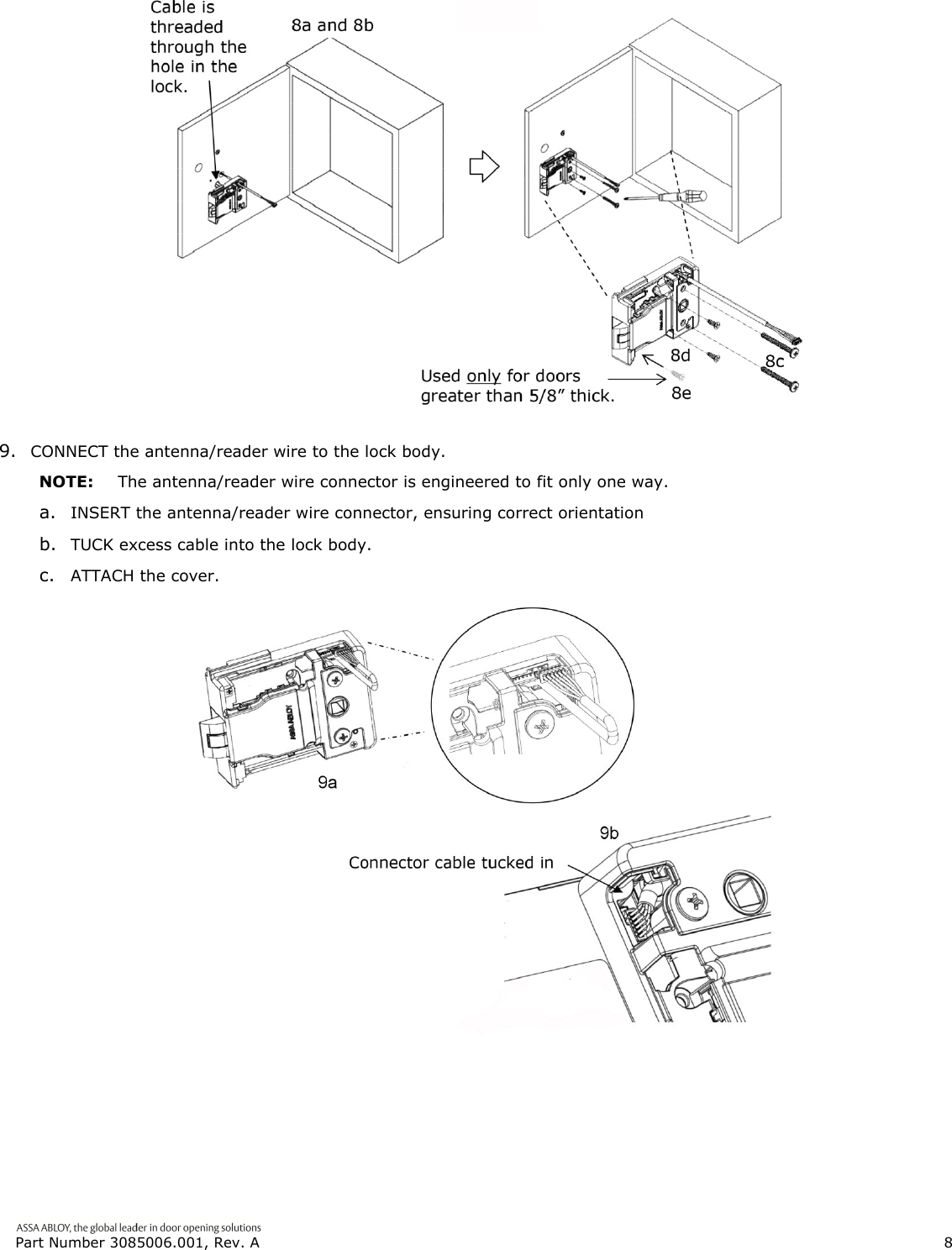
![Part Number 3085006.001, Rev. A 7 7. INSTALL the Antenna/Reader. CAUTION Pinching the wires may prevent the Reader and Lock from properly functioning. a. PLACE and HOLD the antenna/reader to the outside of cabinet, routing the wire through the 1/2” [12.70 mm] offset hole, and ENSURE the knob is in the locked position in the vertical. NOTE: Using the table below will help determine the length of the top mount screw needed, based on the thickness of the cabinet door. b. INSTALL the top mount screw to attach the antenna/reader to the outside case. 8. INSTALL the lock. a. REMOVE the cover from lock. b. PLACE the lock on the inside of the door, threading the cable through the lock. c. ATTACH the lock to the antenna/reader using two 8-32 [4.00 mm] lock mount screws (see Table 2 for length), and TIGHTEN the screws. d. INSTALL the two #6 [3.5 mm] self-threading screws, and TIGHTEN. NOTE: The third #6 [3.5 mm] self-threading screw is important to achieve maximum holding force for doors greater than 5/8” [15.88 mm] thick. e. INSTALL the third #6 [3.5 mm] self-threading screw only if the door is greater than 5/8” [15.88 mm] thick, using the lock as a guide, and TIGHTEN.](https://usermanual.wiki/Hanchett-Entry-Systems/K200/User-Guide-2607277-Page-7.png)