Hanchett Entry Systems RF0010 Prox Reader User Manual FCC Part 15
Hanchett Entry Systems, Inc. Prox Reader FCC Part 15
Manual

5015 B.U. Bowman Drive Buford, GA 30518 USA Voice: 770-831-8048 Fax: 770-831-8598
Certification Exhibit
FCC ID: VC3-RF0010
IC: 7160A-RF0010
FCC Rule Part: 15.209
IC Radio Standards Specification: RSS-210
ACS Report Number: 10-0242.W06.12.A
Manufacturer: Hanchett Entry Systems, Inc
Model: RF0010
Manual
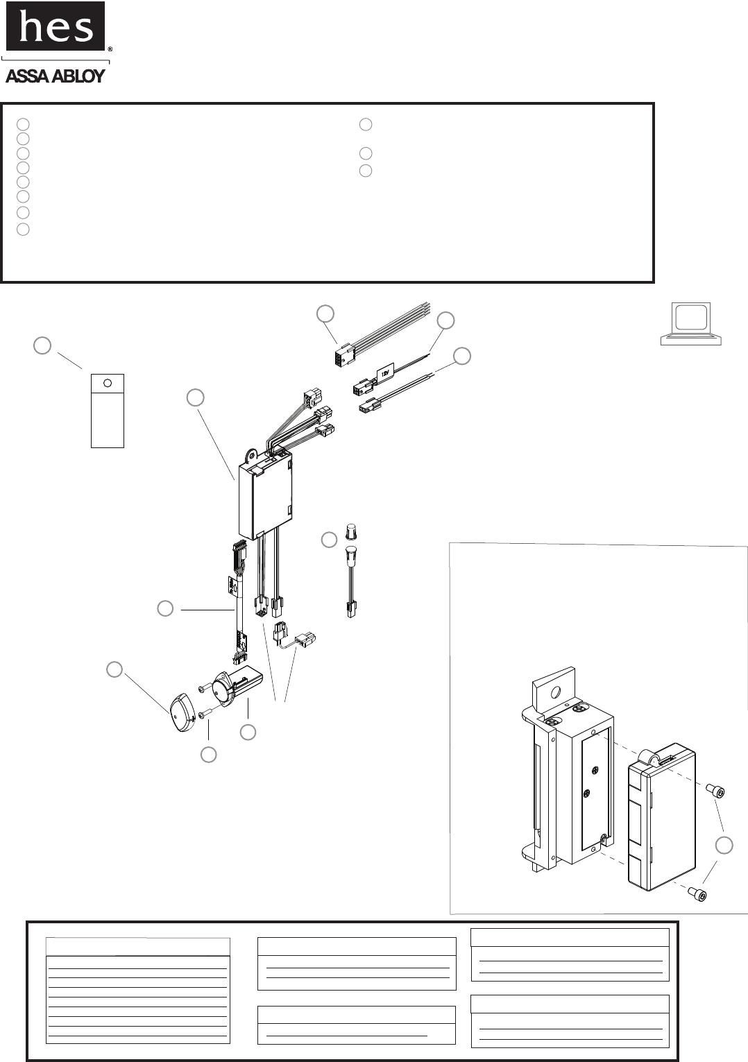
3
8
9
1
2
Prox Module
#6-32 Module Mounting Screws (for optional strike mount)
Reader/Antenna Body
Reader/Antenna Mounting Screws
Reader/Antenna Cover
1
2
3
4
5
6
724” Cable (connecting reader/antenna and strike)
8
9
2 pin DPS & LBM Pigtail Connector
11
Dielectric Grease (for humid applications)
10
4 pin 12V Strike Power Pigtail
8 pin Connector (Data Module) Prox Pigtail
RF0010
Installation Instructions
Prox Module
HES, Inc.
22630 N. 17th Ave.
Phoenix, AZ 85027
800-626-7590
The Prox Module can either be supported by
the electrical connection to the Electric Strike,
or by mounting it directly to the back of several
HES Electric Strikes using the #6-32 Module
Mounting Screws. Do not attempt to support
the Prox Module with the 24” Antenna Cable.
Access Control System
Control Panel and Power Supply
(By others)
8 Pin Connector (Data Module)
Red (+) Board Power
Black ( ) Board Power
Green Data 0
White Data 1
Yellow LED/Buzzer
Blue Not Used
Orange Not Used
Brown Not Used
2 Pin Connector (Door Position Switch)
Wire plugs into Hybrid Electric Strike
Wiring Diagram
-
2 pin Connector (Strike Module)
Tan Common
Pink Door Closed and Latch Engaged
4 Pin Connector (12V Strike Power)
Red (12VDC +) Strike Power
Black (−) Strike Power
4 Pin Connector (24V Strike Power)
Violet (24VDC +) Strike Power
Black
(−) Strike Power
OR
Dielectric
Grease
6
11
7
4
5
10
Door Position Sensor (DPS)
To Electric Strike
RF0010: Prox Module
Installation Directions
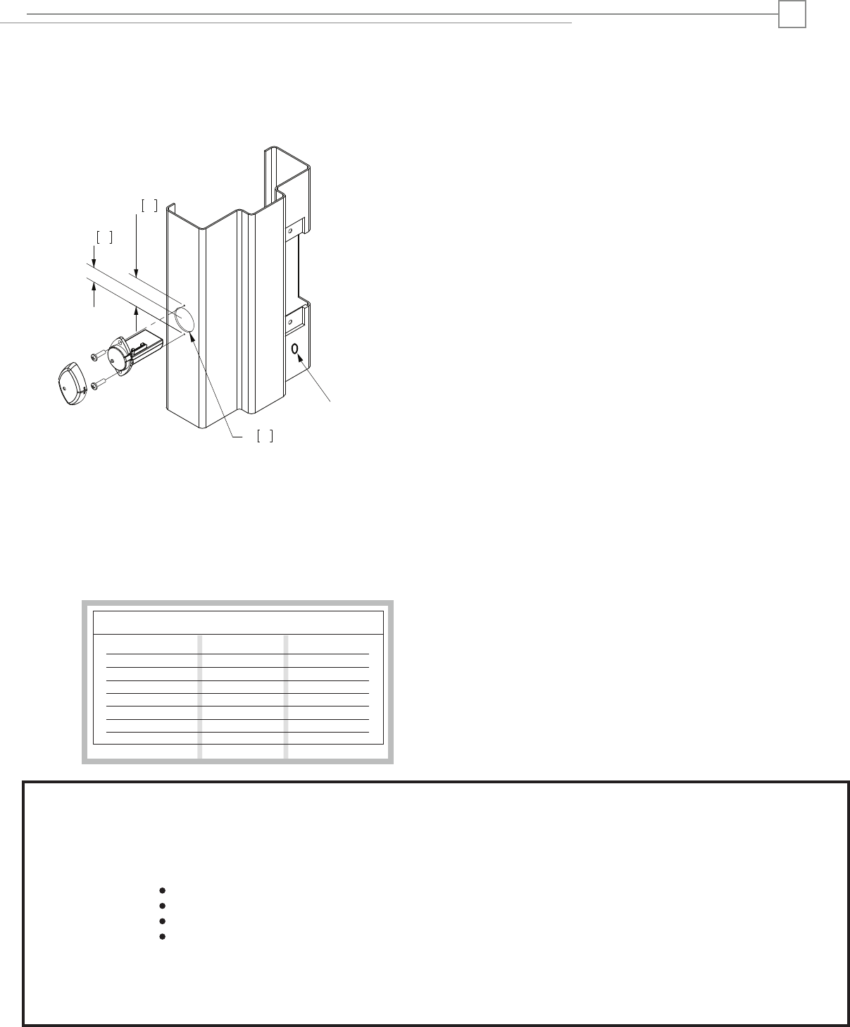
1. Prepare door jamb for the Electric Strike per the appropriate
template provided with the electric strike.
2. Drill a 1” diameter hole for Reader/Antenna install per the
image below The Reader/Antenna may be positioned as desired,
within the limits of the 24”cable connected to the Prox Module.
4. Drill a 3/8” hole for the door position switch (DPS) as required.
3. The Prox Module can be mounted directly to the back of
the several HES Electric Strikes, or supported in the frame by
its electrical connection to the Electric Strike. Do not attempt
to support the Prox Module with the 18” Antenna Cable.
To attach the Prox Module to the Electric Strike, see page 1.
Prepare Frame and Strike
10. Install the Electric Strike unit in jamb cutout.
11. When power is supplied, the LED will turn red, while the beeper
beeps 3 times. This sequence indicated the micro-controller is
operating properly.
1. Present an Prox ID card to the Reader/Antenna. The LED
will turn green, while the beeper beeps once. This indicates
that the card was read successfully. Simultaneously, the
keeper will click open. This indicates that communication
between the control panel and the Electric Strike is
operational.
Testing and Operation
Connect Components and Wiring
Wire Gauge Diagram
12VDC
100’ or less 24 Gauge
2
6. Verify that the wires running from the control panel are of
adequate wire gauge (see Wire Gauge Diagram below).
Connect the wire leads of the three pigtails provided to the
control panel wiring based on the wiring diagram on page 2
and the appropriate termination at the control panel.
7. Mount the door position switch (DPS) into the frame. Route
the 10” cable back to the Electric Strike and connect it to the 2
pin connector coming out of the Electric Strike. It does not
matter which 2 pin connector is used. The LBM & DPS are wired
in series--a ‘closed’ electrical circuit depicts a closed door and
extended latchbolt into the hybrid Electric Strike.
9. Attach the 8, 4 and 2 pin connectors at the Electric Strike
to the equivalent pigtail connectors routed from the control
panel. Dielectric grease should be applied to the pigtail electrical
terminals if used in a humid environment.
8. Secure the Reader/Antenna Mounting Plate to the frame
using the #6-32 screws provided. Connect the 24” cable to
the Reader/Antenna, snap the Reader/Antenna to the
Reader/Antenna Mounting Plate and pull the 24” cable
through to the Prox Module.
Distance In ft, Round Trip
100’ to 200’
200’ to 300’
300’ to 400’
400’ to 500’
500’ to 600’
600’ to 700’
22 Gauge
22 Gauge
22 Gauge
20 Gauge
20 Gauge
18 Gauge
24VDC
24 Gauge
24 Gauge
24 Gauge
22 Gauge
22 Gauge
22 Gauge
20 Gauge
5. Select the 12V AC/DC pigtail.
Reader/Antenna
©2010 HES, Inc.
3078006.009 rev A
Warning :
Changes or modification to this device not expressly approved by HES, Inc., could void the user’s authority to operate the equipment.
NOTE: This equipment has been tested and found to comply with the limits for a class [B] digital device, pursuant to Part 15 of the FCC Rules. These
nable protection against harmful interference in a residential installation. This equipment generates, uses, and
can radiate radio frequency energy and, if not installed and
used in accordance with the instructions, may cause harmful int erference to radio
guarantee that interference will not occur in a particular installation. If this equipment does cause harmful
to radio or television reception, which can be determined by turning the equipment off and on, the user is encouraged to try to correct
the interference by one or more of the following measures:
Reorient or relocate the receiving antenna.
Increase the separation between the equipment and receiver.
Connect the equipment into an outlet on a circuit different from that to which the receiver is connected.
Consult the dealer or an experienced radio/TV technician for help
This class [B] digital apparatus meets all requirements of the Canadian Interference Causing Equipment Regulations.
Operation is subject to the following two conditions: (1) this device may not cause harmful interference, and (2) this device must accept any inter-
ference received, including interference that may cause undesired operation. Cet appareillage numérique de la classe [B] répond à toutes les
exigences de l’inerférencé canadienne causant des réglements d’équipement. L’opération est sujette aux deux conditions suivantes: (1) ce dispositif
l’interférence nocive, et (2) ce dispositif doit accepter n’importe quelle interférence reçue, y compris l’interférence quipeut causer
l’opération peu désirée.
limits are designed to provide reaso
communications. However, there is no
interference
peut ne pas causer
33
17
25
1-5/16”
5/8”
1”
DPS: 3/8” [10]