Handlink Technologies WAP-001R2 In Wall Box Access Point User Manual
Handlink Technologies Inc. In Wall Box Access Point
User manual
Copyright Notice
Copyright © 2005-2015 Handlink Technologies Inc. All rights reserved. No part of this document may
be copied, reproduced, or transmitted by any means, for any purpose without prior written permission.
Disclaimer
We shall not be liable for technical or editorial errors or omissions contained herein; nor for incidental or
consequential damages resulting from furnishing this material, or the performance or use of this
product. We reserve the right to change the product specification without notice. Information in this
document may change without notice.
Trademarks
Microsoft Win98, Windows 2000 and WinXP are registered trademarks of Microsoft Corporation.
General: All other brand and product names mentioned herein may be registered trademarks of their
respective owners. Customers should ensure that their use of this product does not infringe upon any
patent rights. Trademarks mentioned in this publication are used for identification purposes only and
are properties of their respective companies.

In Wall Box Access Point
2
Table of Contents
1Introduction ------------------------------------------------------------------------------------------------------------4
1-1Package Contents ---------------------------------------------------------------------------------------------------4
1-2Features ----------------------------------------------------------------------------------------------------------------5
1-3Precautions------------------------------------------------------------------------------------------------------------5
1-4Outlook------------------------------------------------------------------------------------------------------------------5
1-4-1Rear Panel---------------------------------------------------------------------------------------------------7
1-5Technical Specifications -------------------------------------------------------------------------------------------7
1-5-1Hardware Specifications ---------------------------------------------------------------------------------7
1-5-2Software Specifications ----------------------------------------------------------------------------------8
2Installation -----------------------------------------------------------------------------------------------------------10
2-1Installation Requirements----------------------------------------------------------------------------------------11
2-2Getting Start---------------------------------------------------------------------------------------------------------12
3 Configuring the In Wall Access Point -----------------------------------------------------------------------------15
3-1Internet Settings----------------------------------------------------------------------------------------------------17
3-2Wireless --------------------------------------------------------------------------------------------------------------20
3-2-1Wireless Basic Setting----------------------------------------------------------------------------------20
3-2-2Wireless Advanced Setting----------------------------------------------------------------------------21
3-2-3Multi-SSID Settings -------------------------------------------------------------------------------------22
3-3Advanced ------------------------------------------------------------------------------------------------------------24
3-3-1Management ----------------------------------------------------------------------------------------------24
3-3-2Daily Report -----------------------------------------------------------------------------------------------26
3-3-3FTP ----------------------------------------------------------------------------------------------------------27
3-3-4SNMP -------------------------------------------------------------------------------------------------------28
3-4System Tool ---------------------------------------------------------------------------------------------------------29
3-4-1Configuration----------------------------------------------------------------------------------------------29
3-4-2Firmware ---------------------------------------------------------------------------------------------------30
3-4-3Ping Command-------------------------------------------------------------------------------------------32
3-4-4Restart ------------------------------------------------------------------------------------------------------32
Appendix A Signal Connection Arrangements -------------------------------------------------------------------- 33
In Wall Box Access Point 3
Appendix B Regulations/EMI Compliance -------------------------------------------------------------------------34
LIMITED WARRANTY---------------------------------------------------------------------------------------------------35

In Wall Box Access Point
4
1 Introduction
The WAP-001 Access Device revolutionizes the way wireless and wired IP-based services are
delivered to hospitality and residential properties. The WAP-001 integrates wired and wireless
connectivity into a small unit that can be quickly and discretely installed in a standard wall box. The
WAP-001 provides Two Ethernet ports, a 2.4GHz 802.11b/g/n wireless access point. The WAP-001
requires a single powered cable drop to unlock its utility and, through the reduction in cabling, switch
ports, and power-sourcing equipment, the WAP-001 represents the best value for the delivery of next
generation entertainment services.
1-1 Package Contents
Please inspect your package. The following items should be included:
◎ WAP-001
z One In Wall Box Access Point
z One UTP Ethernet/Fast Ethernet cable (Cat.5 Twisted-pair) (10cm)
z One Wall fixed plate
z One Quick Installation Guide
z One CD Contents
If any of the above items are damaged or missing, please contact your dealer immediately.
In Wall Box Access Point 5
1-2 Features
z Wireless data rates up to 300Mbps
z Comprehensive security
64/128-bit WEP encryption
WPA encryption
WPA2 encryption
z Intelligent Management
1-3 Precautions
z Never remove or open the cover. You may suffer serious injury if you touch these parts.
z Never install the system in the wet locations.
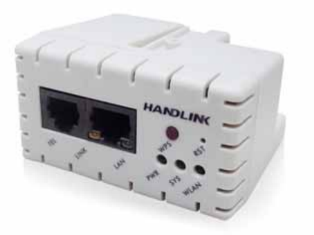
1-4 Outlook
Front Panel
The Front panel of the In Wall Box Access Point shown below.
Figure 1 in Wall Box Access Point Front Panel
In Wall Box Access Point
6
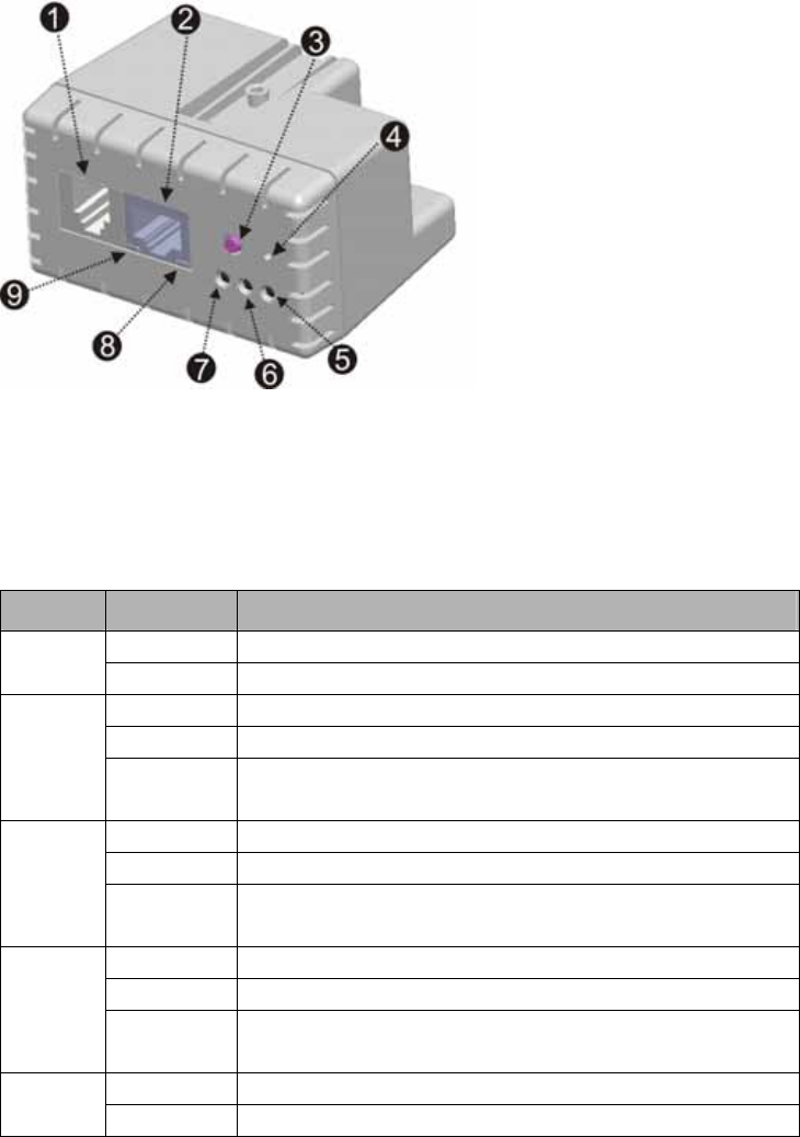
Figure 2 In Wall Box Access Point Front Panel
LEDs Indication
LED State Description
Off The In Wall Box Access Point not receiving electrical power. PWR
Green The In Wall Box Access Point receiving electrical power.
Off The In Wall Box Access Point status is defective.
Green The In Wall Box Access Point status is complete.
SYS
Green
(Blinking)
During firmware upgrades, this system LED will blink.
Off Port has not established any network connection.
Yellow A port has established a valid 10/100Mbps network connection.
LINK / WAN
Yellow
(Blinking)
10/100Mbps traffic is traversing the port.
Off Port has not established any network connection.
Green A port has established a valid 10/100Mbps network connection.
LAN
Green
(Blinking)
10/100Mbps traffic is traversing the port.
Off The Wireless is not ready. WLAN
Green The In Wall Box Access Point has established a valid wireless
1. RJ-45 Transparent Port
2. RJ-45 Ethernet Connector
3. WPS Button
4. Reset Button
5. WLAN
6. SYSTEM
7. POWER
8. LAN Port
9. LINK Port
In Wall Box Access Point 7
connection.
Green
(Blinking)
The Wireless connection is active.
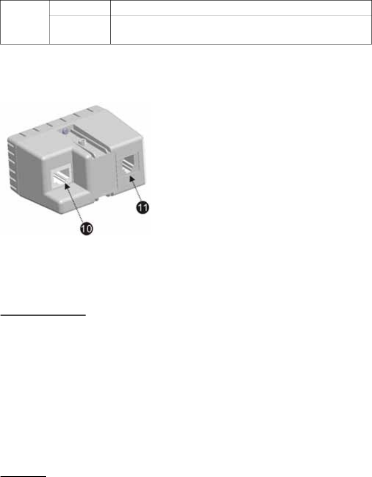
1-4-1 Rear Panel
The rear panel of the In Wall Access Point
Figure 3 In Wall Box Access Point Rear Panel
1-5 Technical Specifications
1-5-1 Hardware Specifications
Network Specification
IEEE802.3 10 Base TX Ethernet
IEEE802.3u 100 Base TX Fast Ethernet
IEEE802.3af Power over Ethernet
IEEE802.11b Wireless LAN
IEEE802.11g Wireless LAN
IEEE802.11n Wireless LAN
ANSI/IEEE 802.3 NWay auto-negotiation
Static IP Client
DHCP Client
Wi-Fi Compatible
Connectors
One LAN Port (10BaseT/100BaseTX Auto cross-over)
One LINK Port (10BaseT/100BaseTX Auto cross-over)
Two RJ-45 transparent used
10. RJ-45 Ethernet Connector(802.3af PoE)
11. RJ-45 transparent

In Wall Box Access Point
8
Encryption
WEP (Wired Equivalent Privacy) 64/128-bit RC4
WPA (Wi-Fi Protected Access)
WPA2 (Wi-Fi Protected Access)
WPA/WPA2 Mixed Mode
WMM
LED Indicators
One POWER LED
One Link 10/100M Link/Activity LED
One LAN 10M/100M Link/Activity LED
One Wireless Link/Activity LED
One System LED
Environment Conditions
Operating Temperature: 0 to 50°C
Storage Temperature: -10 to 60°C
Operating Humidity: 10~80% non-condensing
Storage Humidity: 10% to 90% non-condensing
Certifications
FCC part 15 Class B,
Dimension
Size: 39.3(W) x 71.6(L)x 55(H)/ mm
Weight: About 85g (Net)
1-5-2 Software Specifications
Networking
• IEEE802.3 10BaseT Ethernet
• IEEE802.3u 100BaseTX Fast Ethernet
• IEEE802.3af Power over Ethernet
• IEEE802.11b Wireless LAN
• IEEE802.11g Wireless LAN
• IEEE802.11n Wireless LAN
• Static IP WAN Client
• DHCP WAN Client

In Wall Box Access Point 9
Security and Firewall
• WEP
• WPA
• WPA2
• WPA/WPA2 Mixed Mode
• WMM
Management
• Web-based Management Tool
• Firmware Upgrade via HTTP/TFTP
• Backup/Restore/Factory Default Setting
• Remote Authorized Management
• SNMP
• System Information Table
In Wall Box Access Point
10
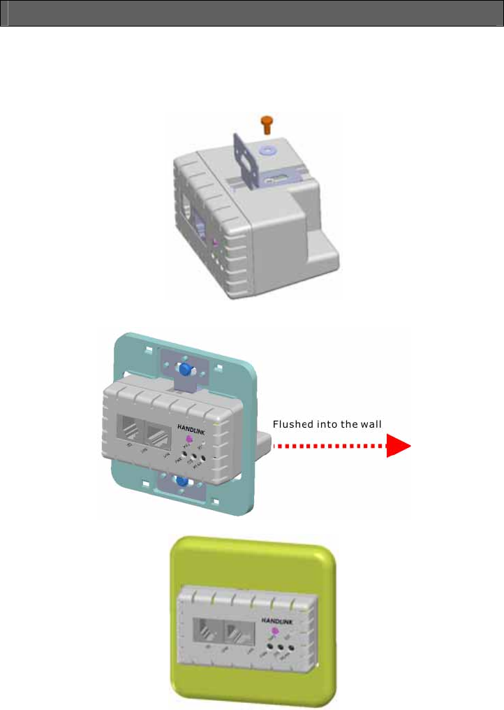
2 Installation
The followings are instructions for setting up the In Wall Access Point. Refer to the illustration and
follow the simple steps below to quickly install your In Wall Access Point.
Step 1:Slide the Bracket to align with screw holes on the In Wall Access Point, and fasten the Bracket
tightly with screws on the In Wall Access Point
Step 2:Slide the WAP-001 into the Bottom Faceplate and fasten tightly into the Bottom Faceplate until
it’s flushed into the wall.
Step 3:Line-up and push the Top faceplate onto Bottom faceplate until snaps securely into place.

In Wall Box Access Point 11
2-1 Installation Requirements
Before installing the In Wall Access Point, make sure your network meets the following
requirements.
System Requirements
The In Wall Box Access Point requires one of the following types of software:
z Windows 98 Second Edition/NT/2000/XP/Vista/Win 7
z Red Hat Linux 7.3 or later version
z MAC OS X 10.2.4 or later version
z Any TCP/IP-enabled systems like Mac OS and UNIX (TCP/IP protocol installed)
z Web Browser Software (Microsoft I.E 5.0 or later version or Netscape Navigator 5.0 or later
version)
z One computer with an installed 10Mbps, 100Mbps or 10/100Mbps Ethernet card
z UTP network Cable with a RJ-45 connection (Package contents)
Note: Prepare twisted-pair cables with RJ-45 plugs. Use Cat.5 cable for all connections. Make sure
each cable not exceed 328 feet (Approximately 100 meters).
In Wall Box Access Point
12
2-2 Getting Start
WAP-001 support web-based configuration. Upon the completion of hardware installation, can be
configured through PC/NB by web browser such as Internet Explorer, Firefox, and Opera.
¾ Default IP Address:10.59.1.254
¾ Default Subnet Mask:255.255.255.0
¾ Default Username and Password: admin/admin
Note
:
Set the IP segment of the administrator’s computer to be in the same range as WAP-001 for
accessing the system. Do not duplicate the IP address used here with IP address of WAP-001 or
any other device within the network.
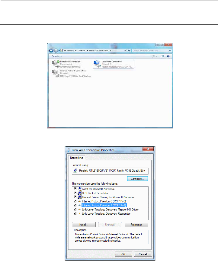
Step1:Click StartÆSettingÆControl Panel, and then “Control Panel” window appears, Click on
“Network connection” window appears.
Step2:In “Local Area Connection properties” window, select “Internet Protocol (TCP/IPv4)” and
click on “properties” button.
In Wall Box Access Point 13
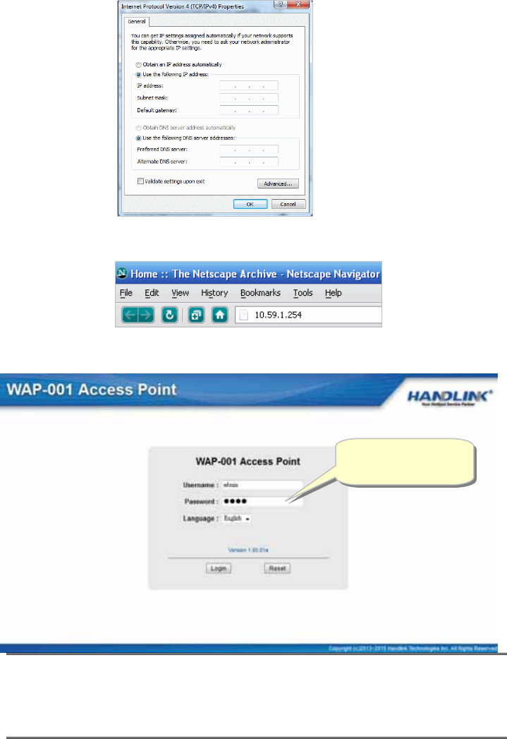
Step 3:Launch your browser, and then enter the factory default IP address 10.59.1.254 in your
browser’s location box. Press Enter.
Step 4:.The WAP-001 login screen will appear. In the Username and Password field, type the factory
default user name admin and password admin and click Setup. The WAP-001 setup screen will
appear.
Note: It is important to remember your password. If for any reason you lose or forget your password,
press the reset button located on the top of the device. Reset action will re-initialize the
settings. All configurations, including username, password and IP address(s), will be reset,
and requires re-entering.
Example:
IP Address:10.59.1.109
Subnet Mask:255.255.255.0
Username: admin
Password: admin
In Wall Box Access Point
14
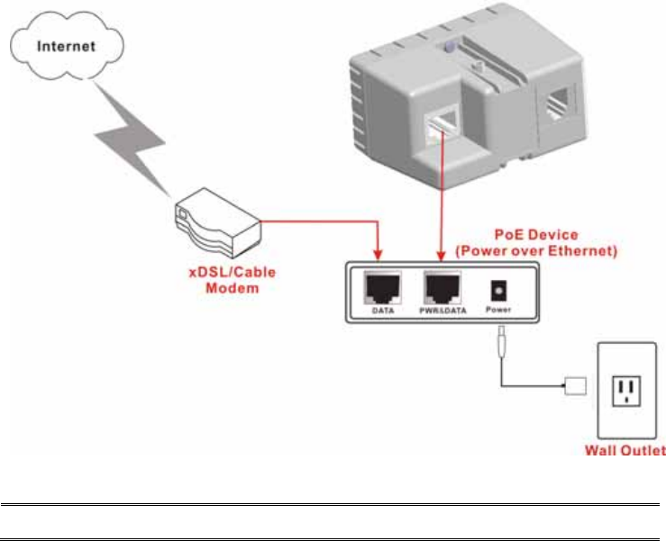
PoE (Power over Ethernet) Application
Note: To use the WAP-001’s PoE feature, follow the instructions for your specific PoE device.
In Wall Box Access Point 15
3 Configuring the In Wall Access Point
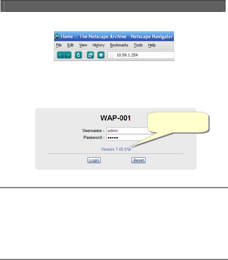
Step 1: Start your browser, and then enter the factory default IP address 10.59.1.254 in your browser’s
location box. Press Enter.
Figure 4 Web Browser Location Field (Factory Default)
Step 2: The In Wall Box Access Point configuration tools menu will appear. In the Username and
Password field, type the factory default user name admin and password admin and click
Login.
Figure 5 Configuration Tools Menu
Note:
)
This Web agent is best viewed with IE 5.0 or Netscape 6.0 and above browsers.
)
Username and Password can consist of up to 20 alphanumeric characters and are case sensitive.
)
If for some reason your password is lost or you cannot gain access to the In Wall Box Access Point
Configuration Program, please press the reset button to load the device to manufacturer defaults.
)
If the In Wall Box Access Point doesn’t send packet in 5 minutes (default), the In Wall Box Access
Point will logout automatically.
) Proxy needs to set disable first when administrator accesses admin UI
Username: admin
Password: admin
In Wall Box Access Point
16
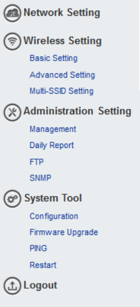
The Setting enables you to configure advanced settings related to accessing the Internet;Display in
Wall Box Access Point basic status and process Firmware upgrade, change password and backup or
restore configuration. Including,
z Network Setting
z Wireless Setting
¾ Basic
¾ Advanced
¾ Multi-SSID Setting
z Administration Setting
¾ Management
¾ Daily Report
¾ FTP
¾ SNMP
z System Tool
¾ Configuration
¾ Firmware Upgrade
¾ Ping
¾ Restart
z Logout
Figure 6 Configuration Tools Menu
In Wall Box Access Point 17
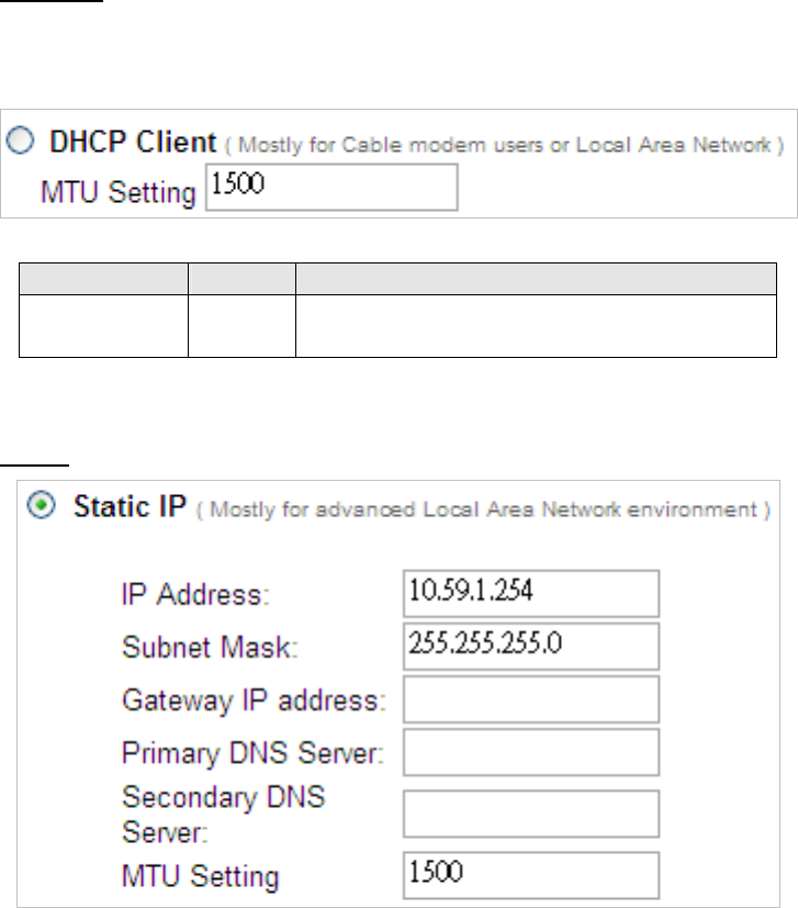
3-1 Internet Settings
The IP address can be manually set or automatically assigned by a DHCP server on the LAN. If you are
manually setting the IP address, Subnet mask, and Gateway IP address settings, set them
appropriately, so that they comply with your LAN environment.
Figure 7 the TCP/IP Setting
DHCP Client
The device can work as a DHCP client. This allows the device to obtain the IP address and other
TCP/IP settings from your switch or IP router. If your device comes with this feature, please enable Use
DHCP Client.
Figure 8 DHCP Client Setting Screen
Item Default Description
MTU Setting 1500 MTU (Maximum Transfer Unit) specifies maximum
transmission unit size.
Static IP

In Wall Box Access Point
18
Figure 9 Static IP Setting Screen
Item Default Description
IP Address 10.59.1.254 Enter the IP address for the xDSL/Cable connection (provided
by your ISP).
Subnet Mask 255.255.255.0 Enter the subnet mask for the IP address.
Gateway IP
Gateway
Empty Enter the Gateway IP address for the xDSL/Cable connection
Primary DNS
Server
Empty A primary DNS server IP address for the xDSL/Cable
connection
Secondary
DNS Server
Empty A secondary DNS server IP address for the xDSL/Cable
connection. If the primary DNS Server IP were not available,
meanwhile, Secondary DNS Server IP would start in the same
time.
MTU Setting 1500 MTU (Maximum Transfer Unit) specifies maximum
transmission unit size.
In Wall Box Access Point 19
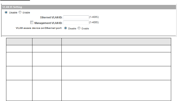
VLAN ID Setting
Item Default Description
VLAN ID Disable Enable or Disable Ethernet and wireless VLAN ID Function
Ethernet
VLAN ID
Empty Defines the VLAN ID for the port (1~4095).
Management
VLAN ID
Disable Click Tick to enable management VLAN ID, and defines the
VLAN ID port number (1~4095)
VLAN aware
device on
Ethernet port
Disable Enable or disable VLAN aware device on Ethernet port
In Wall Box Access Point
20
3-2 Wireless
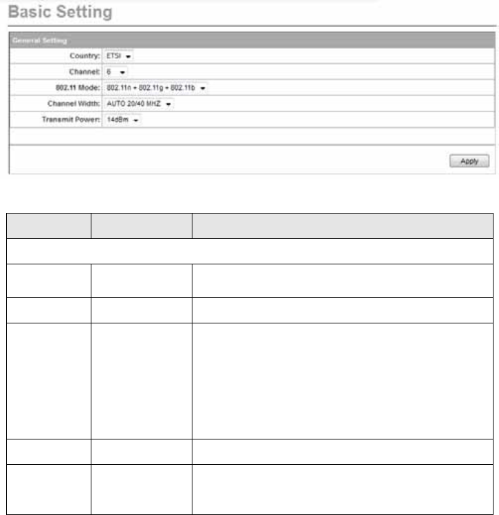
3-2-1 Wireless Basic Setting
Figure 10 Wireless Basic Setting Screen
Item Default Description
General Settings
Country ETSI Select the desired country code. The options are US and
ETSI.
Channel 6 Select the channel ID for wireless connection.
802.11 Mode 802.11g+802.11b
Select the 802.11 mode of following::
-802.11n+802.11g+802.11b
-802.11n+802.11g
-802.11g+802.11b
-802.11n only
-802.11g only
-802.11b only
Channel Width Auto 20/40MHz Select of channel width of Auto 20/40 MHz or 20MHz
Transmit Power 14 dBm
To Adjust the output power of the system to get the
appropriate coverage of your wireless network. Select the
value that you need for your environment.
In Wall Box Access Point 21
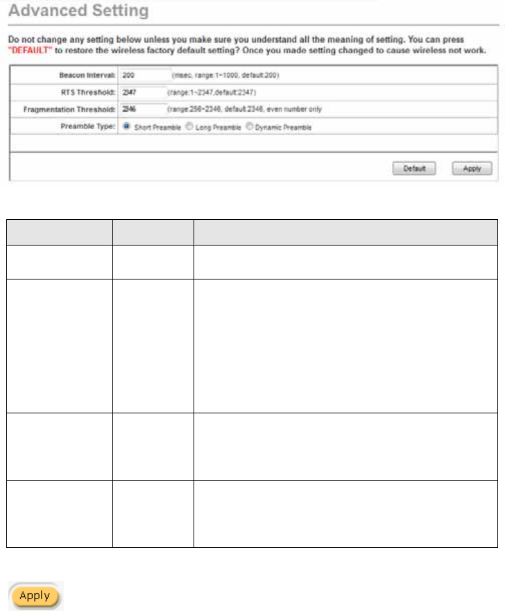
3-2-2 Wireless Advanced Setting
Figure 11 Wireless Advanced Setting Screen
Item Default Description
Beacon Interval 200 This value valid range is 1 to 1000 indicates the frequency
interval of the beacon.
RTS Threshold 2347
This value valid range is 256-2342. This setting determines
the packet size at which the Wireless Subscriber Gateway
issues a request to send (RTS) before sending the packet. A
low RTS Threshold setting can be useful in areas where
many client devices are associating with the Wireless
Subscriber Gateway, or in areas where the clients are far
apart and can detect only the Wireless Subscriber Gateway
and not each other.
Fragmentation
Threshold 2446
This setting determines the size at which packets are
fragmented. Enter a setting ranging from 256 to 2432 bytes.
Use a low setting in areas where communication is poor or
where there is a great deal of radio interference.
Preamble Type Dynamic
preamble
The preamble type is a section of data at the head of a
packet that contains information and client devices need
when sending and receiving packets. The setting menu
allows you to select a long, short or dynamic preamble type.
Click Apply button to save the new settings.
In Wall Box Access Point
22
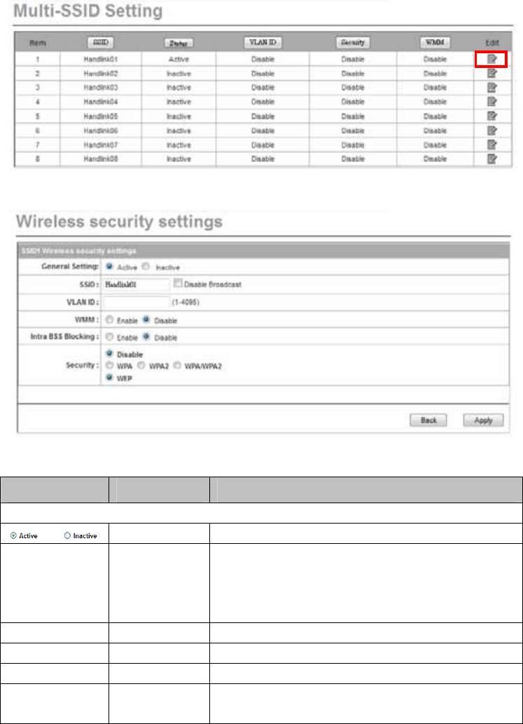
3-2-3 Multi-SSID Settings
Figure 12 Wireless Security Setting Screen
Figure 13 Wireless Security Setting Screen
Item Default Description
General Setting
Active Active or Inactive the ESSID to activation in your network.
ESSID Wireless The ESSID is the unique name that is shared among all
points in a wireless network. It is case sensitive and must
not exceed 32 characters.
Broadcast Enable Enable or Disable Broadcast
VLAN ID Empty Defines the VLAN ID for the port (1~4095).
WMM Disable Enable or Disable WMM Support
Intra-BSS
Blocking
Disable Enable or Disable intra-Bss Blocking.
In Wall Box Access Point 23
Security Setting
Security Disable
Select disable to allow wireless station to communicate with
the device without any data encryption. Select enable to
enable WPA or WEP data encryption.
WPA/WPA2 /Mixed Mode Encryption Wi-Fi Protected Access Encryption
Pre-shared Key Empty Enter a pre-shared key from 8 to 63 case sensitive ASCII
characters.
Group Key
Re-Keying
86400 Seconds Enter a number in the field to set the force re-keying interval.
Pre-shared Key Empty Enter a pre-shared key from 8 to 63 case sensitive ASCII
characters.
Group Key
Re-Keying
86400 Seconds Enter a number in the field to set the force re-keying interval.
WEP
WEP Key 1
This selects which of the Keys the In Wall Box Access Point
uses when it transmits. You can change the selected encryption
key every now and then to increase the security of your network.
Note: You have to configure all WEP keys (1~4), and select one
of the four WEP key.
Enter 5 characters (case sensitive) for ASCII 64-bit WEP Key.
Enter 10 characters (case sensitive) for Hex 64-bit WEP Key.
Enter 13 characters (case sensitive) for ASCII 128-bit WEP Key.
Enter 26 characters (case sensitive) for Hex 128-bit WEP Key.
Click Apply button to save the new settings.
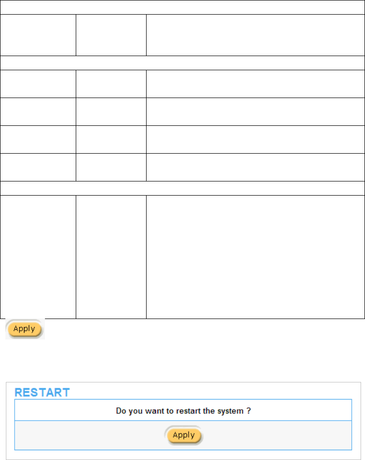
Figure 14 Restart Dialog Box
Click Apply button, the restart dialog box appears. Click on Apply to restart the system.
In Wall Box Access Point
24
3-3 Advanced
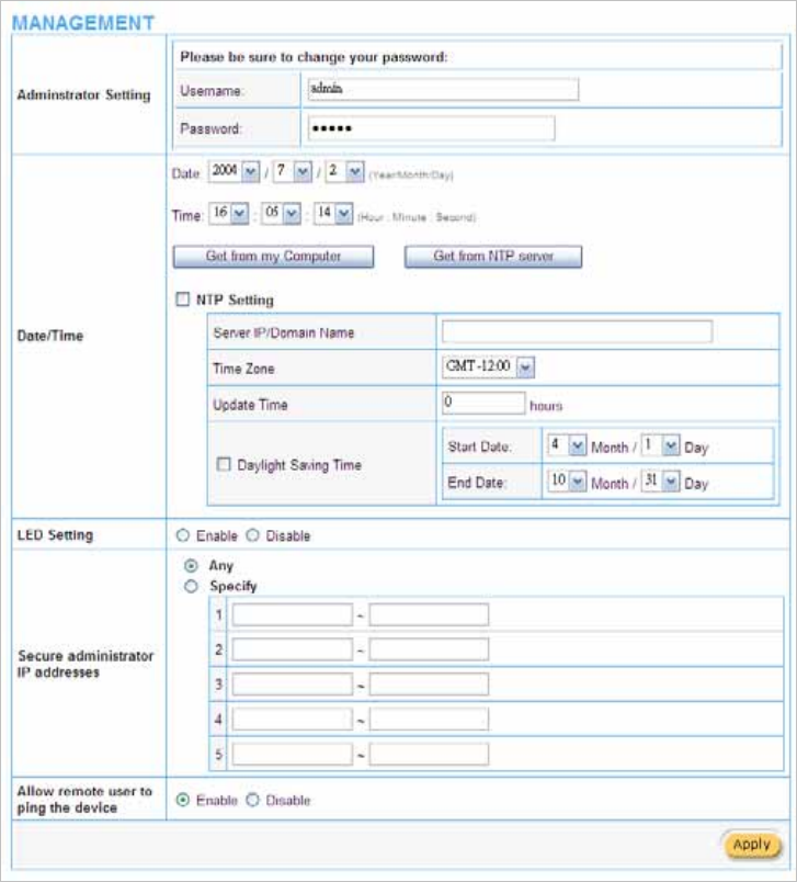
3-3-1 Management
Define the In Wall Box Access Point Management configuration
Figure 15 Management Setting Screen
In Wall Box Access Point 25
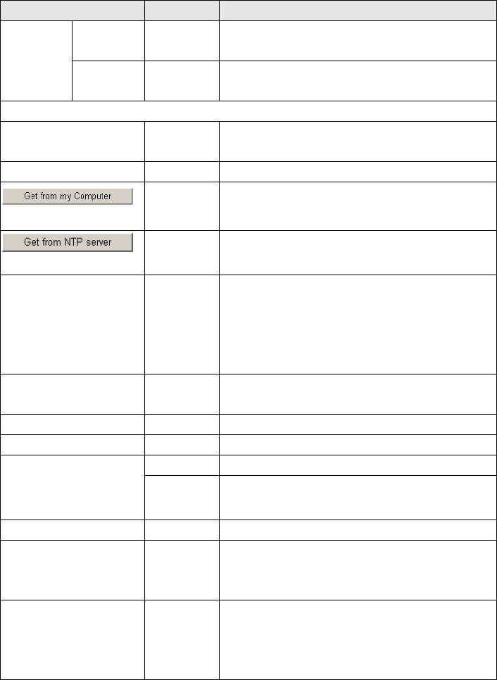
Item Default Description
Username admin The username can consist of up to 20 alphanumeric
characters and is sensitive.
Administrator
Setting Password admin The password can consist of up to 20 alphanumeric
characters and is sensitive.
Date/Time
Date (Year/Month/Day) System Date
The system date of the In Wall Access Point. The valid
setting of year is from 2002 to 2035.
Time (Hour:Minute:Second) System Time The system time of the In Wall Access Point.
- Click “Get from my Computer” button to correct the
system date and time.
- Click “Get from NTP server” button to correct the
system date and time.
NTP Setting Disable
Enables or disables NTP (Network Time Protocol)
Time Server. Network Time Protocol can be utilized to
synchronize the time on devices across a network. A
NTP Time Server is utilized to obtain the correct time
from a time source and adjust the local time.
Server IP/Domain Name Empty Enter the IP address/domain name of NTP server. The
maximum allowed characters length is 100.
Time Zone GMT-12:00 Select the appropriate time zone for your location.
Update Time 0 hours Enter the number of hours for update time.
Disable Enables or disables Daylight Saving Time (DST).
Daylight Saving Time Month/Day Set the Daylight Saving Time (DST) on the In Wall
Access Point. Adjust the begin time and end time.
LED Setting Disable Enable or Disable Device LED lighting.
Secure administrator IP
Addresses Any
Options: Any and Specify. Administrator can specify 5
IP addresses or a range to allow remote control access
from network.
Allow remote user to ping
the device Enable
This function allows remote user to ping the In Wall
Box Access Point through Internet. Ping is normally
used to test the physical connection between two
devices, to ensure that everything is working correctly.
In Wall Box Access Point
26
3-3-2 Daily Report
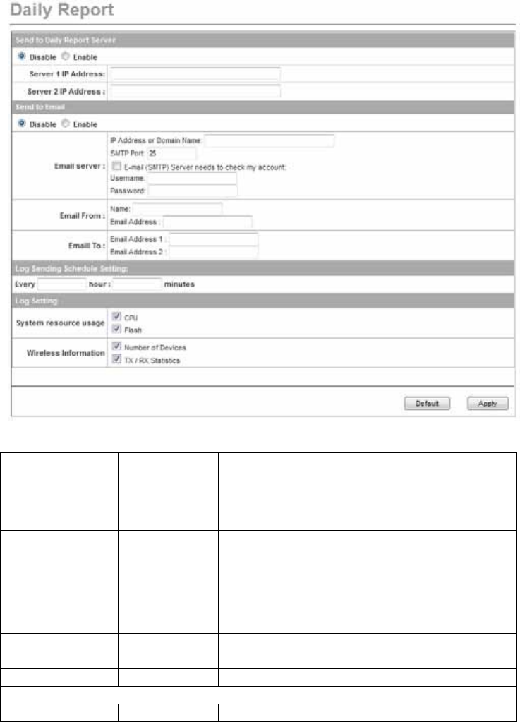
Figure 16 Daily Report Setting Screen
Item Default Description
Send the daily
report to Syslog
Server
Disable Enables or disables the syslog server function.
Server IP Address Empty Enter syslog server’s IP address. The WG-500P
24Roam will send all of its logs to the specified syslog
server.
Server MAC
Address
Empty Enter the syslog server’s MAC address. The WG-500P
24Roam will send all of its logs to the specified syslog
server.
Server 1 IP Address Empty Enter IP address of first syslog server.
Server 2 IP Address Empty Enter IP address of second syslog server.
Send to Email Disable Enables or disables the send to e-mail function.
E-mail Server
IP Address or Empty Enter the SMTP server IP address or domain name. The
In Wall Box Access Point 27
Domain Name maximum allowed characters length is 50.
SMTP Port 25 The SMTP port allowed range is 25 or 2500 to 2599.
E-mail (SMTP)
Server needs to
check my account
Disable If your SMTP server requires authentication before
accepting e-mail, click on check box. These values
(username and password) are supplied by your network
administrator, SMTP server provider or ISP.
Username Empty Enter the username for the SMTP server. The maximum
allowed characters length is 64.
Password Empty Enter the password for the SMTP server
Email From
Name Empty Enter the name you would like to appear in the “message
from” field of your outgoing message. The maximum
allowed characters length is 20.
Email Address Empty Enter your e-mail address. This is the address others will
use to send email to Email Address 1/Email Address 2.
Email To
Email Address 1 Empty Enter your first e-mail address to receive the logs.
Email Address 2 Empty Enter your second e-mail address to receive the logs.
3-3-3 FTP
You can use FTP (File Transfer Protocol) to upload and download the WAP-001’s firmware and
configuration files. To use this feature, your computer must have an FTP client.
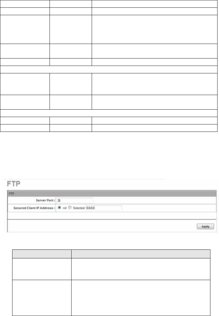
Figure 17 FTP Setting Screen
Item Description
Server Port You may change the server port number for a service if needed,
however you must use the same port number in order to use FTP
to access the WAP-001
Secured Client IP
Address
A secured client is a “trusted” computer that is allowed to
communicate with the WAP-001 using this service.
Select All to allow any computer to access the WAP-001 using
FTP.
Choose Selected to just allow the computer with the IP address
In Wall Box Access Point
28
that you specify to access the WAP-001 using FTP.
Apply Choose “Read”, “Write”, “Trap Recipients” and “All” for different
privileges. The defaults are all “read”.
3-3-4 SNMP
The SNMP Agent Configuration screen enables you to access to your device via Simple Network
Management Protocol. If you are not familiar with SNMP, please consult your Network Administrator or
consult SNMP reference material. You must first enable SNMP on the SNMP Agent Configuration
screen.
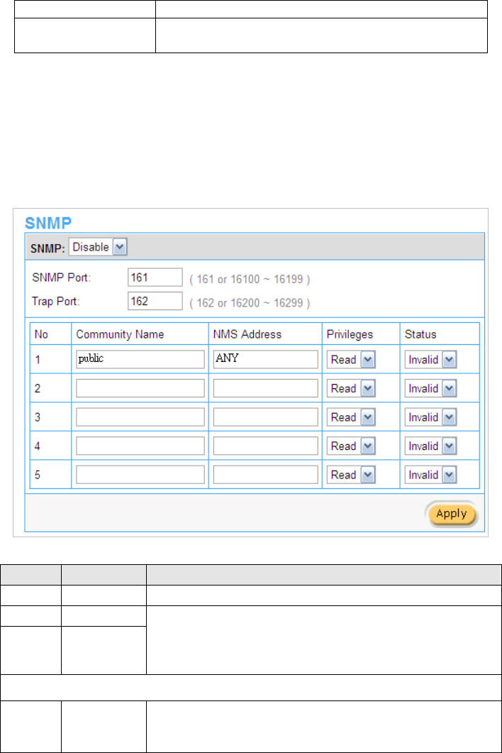
Figure 18 SNMP Setting Screen
Item Default Description
SNMP Disable Disables or enables the SNMP management.
SNMP Port 161
Trap Port 162
If the SNMP enables, also allowed to specific the SNMP port number
via NAT. The allowed SNMP port numbers are 161 (default),
16100-16199 and Trap port numbers are 162 (default), 16200-16299.
This Port setting is useful for remote control via NAT network.
Configuration
Community
Name
public/private Every unit with SNMP enable must be configured to recognize one or
more community names up to 20 characters. The default setting for
the community of entry is “public”
In Wall Box Access Point 29
NMS
Address
ANY The address of the NMS. The default settings for the NMS Networking
are “ANY”.
Privileges Read Choose “Read”, “Write”, “Trap Recipients” and “All” for different
privileges. The defaults are all “read”.
Status Valid/Invalid Chosen “Valid” or “Invalid”. The default setting of entry is all invalid.
3-4 System Tool
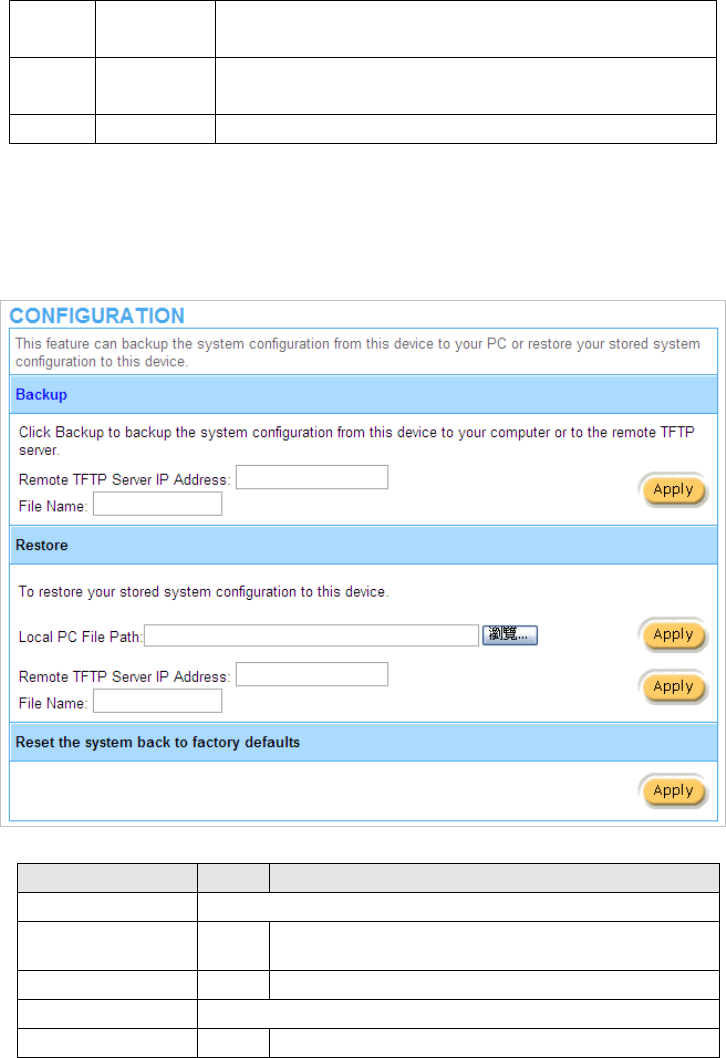
3-4-1 Configuration
This feature can backup the system configuration from this device to your PC or restore your stored
system configuration to this device.
Figure 19 Configuration Setting Screen
Item Default Description
Backup Click it to save the system configuration to your computer. (export.cfg)
Remote TFTP Server IP
Address
Empty Enter the IP address of TFTP Server.
File Name Empty Enter the file name in the File Name field.
Restore Click it to restore your system configuration.
Local PC File Path Empty Enter the file pathname of the system configuration file in the
In Wall Box Access Point
30
Local PC File Path field.
Remote TFTP Server IP
Address
Empty Enter the IP address of TFTP Server.
File Name Empty Enter the file name in the File Name field.
Reset the system back
to factory defaults
Erase all setting and back to factory setting.
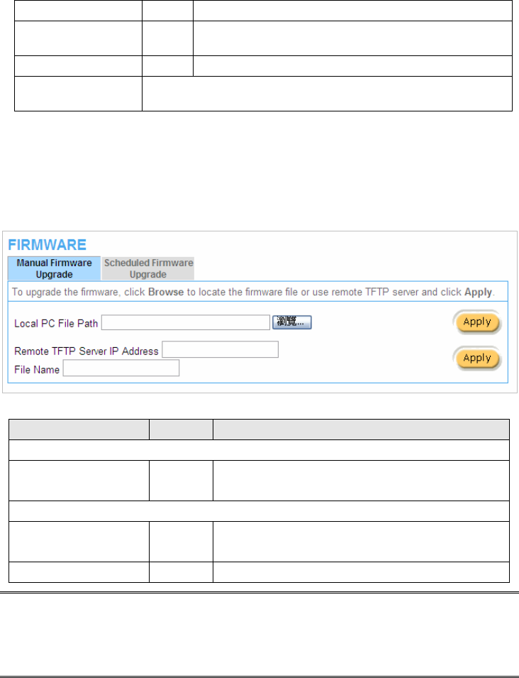
3-4-2 Firmware
The Firmware Upgrade menu loads updated firmware to be permanent in flash ROM. The download file
should be a binary file from factory; otherwise the agent will not accept it. After downloading the new
firmware, the agent will automatically restart it.
z Manual Firmware Upgrade
Figure 20 Manual Firmware Upgrade Setting Screen
Item Default Description
This allow administrator to upgrade the firmware via HTTP.
Local PC File Path Empty Enter the file name and location in the Local PC File Path
field.
This allows administrator use TFTP server to upgrade firmware.
Remote TFTP Server IP
Address
Empty Enter the IP address of TFTP Server.
File Name Empty Enter the file name in the File Name field.
Note:
1. Before downloading the new firmware, users must save the configuration file for restore
configuration parameters of the device.
2. Do not turn the power off during the upgrade process. This will damage the unit.
In Wall Box Access Point 31
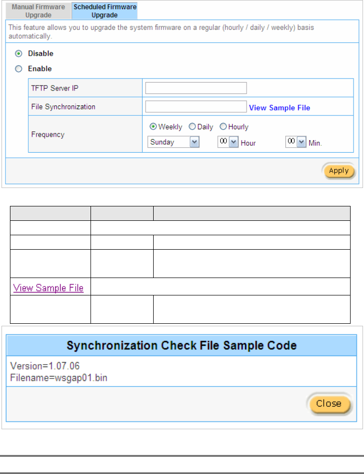
z Scheduled Firmware Upgrade
Scheduled Firmware Upgrade is a program that enables an automatic upgrade to the latest firmware
version through the TFTP server.
Figure 21 Scheduled Firmware Upgrade Setting Screen
Item Default Description
Disable/Enable Disables or enables the scheduled firmware upgrade function.
TFTP Server IP Empty Enter the IP address of TFTP Server.
File Synchronization Empty Enter the file name and location in the File
Synchronization field.
Click the button to display synchronization file example.
Frequency Weekly Set the firmware upgrade time. The default value is
“Weekly”.
Figure 22 Synchronization File Sample Code
Note: Do not turn the power off during the upgrade process. This will damage the unit.
In Wall Box Access Point
32
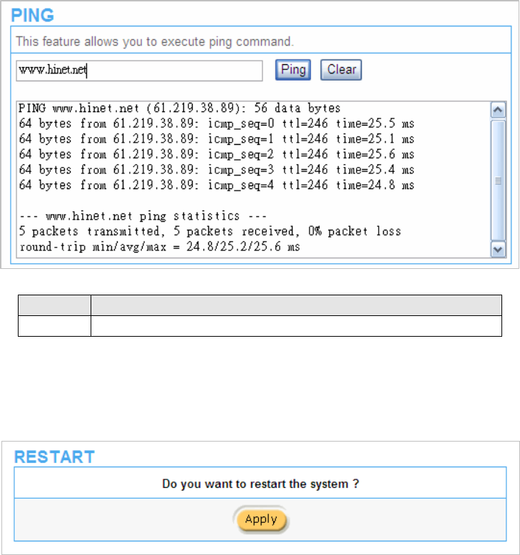
3-4-3 Ping Command
The Ping function can check the Wireless Subscriber Gateway networking connective or not.
Figure 23 Ping Command Screen
Item Description
IP or URL Enter the IP address or the URL link.
3-4-4 Restart
If you’re In Wall Box Access Points not operating correctly, you can choose this option to display the
restart Wireless Subscriber Gateway screen. Clicking the apply button restart the In Wall Access Point,
with all of your settings remaining intact.
Figure 24 Restart Screen
In Wall Box Access Point 33
Logout
If you would like to leave the configuration page, please click apply to exit.
Figure 25 Logout Screen
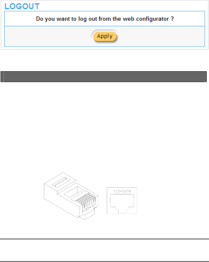
Appendix A Signal Connection Arrangements
RJ-45 Ethernet Port
The In Wall Box Access PointRJ-45 Ethernet port can connect to any networking devices that use a
standard LAN interface, such as a Hub/Switch Hub or Router. Use unshielded twisted-pair (UTP) or
shield twisted-pair (STP) cable to connect the networking device to the RJ-45 Ethernet port.
Depending on the type of connection, 10Mbps or 100Mbps, use the following Ethernet cable, as
prescribed.
10Mbps: Use EIA/TIA-568-100-Category 3, 4 or 5 cables.
100Mbps: Use EIA/TIA-568-100-Category 5 cable.
Figure 26 RJ-45 Connector and Cable Pins
Note: To prevent loss of signal, make sure that the length of any twisted-pair connection does not
exceed 100 meters.

In Wall Box Access Point
34
Appendix B Regulations/EMI Compliance
Federal Communication Commission Interference Statement
This equipment has been tested and found to comply with the limits for a Class B digital device,
pursuant to Part 15 of the FCC Rules. These limits are designed to provide reasonable protection
against harmful interference in a residential installation. This equipment generates uses and can
radiate radio frequency energy and, if not installed and used in accordance with the instructions, may
cause harmful interference to radio communications. However, there is no guarantee that interference
will not occur in a particular installation. If this equipment does cause harmful interference to radio or
television reception, which can be determined by turning the equipment off and on, the user is
encouraged to try to correct the interference by one of the following measures:
● Reorient or relocate the receiving antenna.
● Increase the separation between the equipment and receiver.
● Connect the equipment into an outlet on a circuit different from that to which the receiver is
connected.
● Consult the dealer or an experienced radio/TV technician for help.
FCC Caution: Any changes or modifications not expressly approved by the party responsible for
Compliance could void the user’s authority to operate this equipment.
This device complies with Part 15 of the FCC Rules. Operation is subject to the following two conditions:
(1) This device may not cause harmful interference, and (2) this device must accept any interference
received, including interference that may cause undesired operation.
This device and its antenna(s) must not be co-located or operation in conjunction with any other
antenna or transmitter.
IMPORTANT NOTE:
FCC Radiation Exposure Statement:
This equipment complies with FCC radiation exposure limits set forth for an uncontrolled environment.
This equipment should be installed and operated with minimum distance 20cm between the radiator &
your body. For product available in the USA/Canada market, only channel 1~11 can be operated.
Selection of other channels is not possible.
NCC警語:
(1)「經型式認證合格之低功率射頻電機,非經許可,公司、商號或使用者均不得擅自變更頻率、加大功
率或變更原設計之特性及功能」警語以及(2)「低功率射頻電機之使用不得影響飛航安全及干擾合法通信;
經發現有干擾現象時,應立即停用,並改善至無干擾時方得繼續使用。前項合法通信,指依電信法規定
作業之無線電通信。低功率射頻電機須忍受合法通信或工業、科學及醫療用電波輻射性電機設備之干擾」
警語。
In Wall Box Access Point 35
LIMITED WARRANTY
In Wall Box Access Point
What the warranty covers:
We warrant its products to be free from defects in material and workmanship during the warranty period.
If a product proves to be defective in material or workmanship during the warranty period, we will at its
sole option repair or replace the product with a like product with a like product. Replacement product or
parts may include remanufactured or refurbished parts or components.
How long the warranty is effective:
The Easy Hotspot Kit is warranted for one year for all parts and one year for all labor from the date of
the first consumer purchase.
Who the warranty protects:
This warranty is valid only for the first consumer purchaser.
What the warranty does not cover:
1. Any product, on which the serial number has been defaced, modified or removed.
2. Damage, deterioration or malfunction resulting from:
a. Accident, misuse, neglect, fire, water, lightning, or other acts of nature, unauthorized product
modification, or failure to follow instructions supplied with the product.
b. Repair or attempted repair by anyone not authorized by us.
c. Any damage of the product due to shipment.
d. Removal or installation of the product.
e. Causes external to the product, such as electric power fluctuations or failure.
f. Use of supplies or parts not meeting our specifications.
g. Normal wears and tears.
h. Any other cause that does not relate to a product defect.
3. Removal, installation, and set-up service charges.
How to get service:
1. For information about receiving service under warranty, contact our Customer Support.
2. To obtain warranted service, you will be required to provide (a) the original dated sales slip, (b) your
name, (c) your address (d) a description of the problem and (e) the serial number of the product.
3. Take or ship the product prepaid in the original container to your dealer, and our service center.
4. For additional information, contact your dealer or our Customer Service Center.
Limitation of implied warranties:
THERE ARE NOWARRANTIED, EXPRESSED OR IMPLIED, WHICH EXTEND BEYOND THE
DESCRIPTION CONTAINED HEREIN INCLUDING THE IMPLIED WARRANTY OF
MERCHANTABILITY AND FITNESS FOR A PARTICULAR PURPOSE.
Exclusion of damages:
Our LIABILITY IS LIMITED TO THE COST OF REPAIR OR REPLACEMENT OF THE PRODUCT. We
SHALL NOT BE LIABLE FOR:
1. DAMAGE TO OTHER PROPERTY CAUSED BY ANY DEFECTS IN THE PRODUCT, DAMAGES
BASED UPON INCONVENCE, LOSS OF USE OF THE PRODUCT, LOSS OF TIME, LOSS OF
PROFITS, LOSS OF BUSINESS OPPORTUNITY, LOSS OF GOODWILL, INTERFERENCE WITH
BUSINESS RELATIONSHIPS, OR OTHER COMMERCIAL LOSS, EVEN IF ADVISED OF THE
POSSIBLITY OF SUCH DAMAGES.
2. ANY OTHER DAMAGES, WHETHER INCIDENTAL, CONSEQUENTIAL OR OTHERWISE.
3. ANY CLAIM AGAINST THE CUSOMER BY ANY OTHER PARTY.