Handlink Technologies WG-701 Wireless Router User Manual Copyright Notice
Handlink Technologies Inc. Wireless Router Copyright Notice
User manual

User Manual
R-300NP Wireless Router
Handlink Technologies Inc.
6830607-0010G EN V1.0
無線路由器
(WIFI)
Handlink
Easy Hotspot Kit
2
Copyright Notice
Copyright © 2014-2023 Handlink Technologies Inc. All rights reserved. No part of this document may be
copied, reproduced, or transmitted by any means, for any purpose without prior written permission.
Disclaimer
We shall not be liable for technical or editorial errors or omissions contained herein; nor for incidental or
consequential damages resulting from furnishing this material, or the performance or use of this
product. We reserve the right to change the product specification without notice. Information in this
document may change without notice.
Trademarks
Microsoft Win98, Windows 2000 , WinXP, Win Vista and Win7 are registered trademarks of Microsoft
Corporation.
General: All other brand and product names mentioned herein may be registered trademarks of their
respective owners. Customers should ensure that their use of this product does not infringe upon any
patent rights. Trademarks mentioned in this publication are used for identification purposes only and
are properties of their respective companies.

Easy Hotspot Kit
3
Table of Contents
1 Introduction ----------------------------------------------------------------------------------------------------------------- 5
1-1 Package Contents -------------------------------------------------------------------------------------------------------- 5
1-2 Features --------------------------------------------------------------------------------------------------------------------- 5
1-3 Precautions ----------------------------------------------------------------------------------------------------------------- 5
1-4 Outlook----------------------------------------------------------------------------------------------------------------------- 6
1-4-1 Front Panel ------------------------------------------------------------------------------------------------------- 6
1-4-2 Rear Panel -------------------------------------------------------------------------------------------------------- 7
1-5 Technical Specifications ------------------------------------------------------------------------------------------------ 8
1-5-1 Hardware Specifications -------------------------------------------------------------------------------------- 8
1-5-2 Software Specifications --------------------------------------------------------------------------------------10
2 Installation -----------------------------------------------------------------------------------------------------------------12
2-1 Installation Requirements ----------------------------------------------------------------------------------------------12
2-2 Hardware Setup ----------------------------------------------------------------------------------------------------------13
3. Configuring the R-300NP ----------------------------------------------------------------------------------------------14
3-1 Wizard Setup --------------------------------------------------------------------------------------------------------------14
3-2 Advanced Setup ----------------------------------------------------------------------------------------------------------22
3-2-1 System ------------------------------------------------------------------------------------------------------------23
3-2-2 WAN/LAN --------------------------------------------------------------------------------------------------------25
3-2-3 Server -------------------------------------------------------------------------------------------------------------31
3-2-4 Authentication---------------------------------------------------------------------------------------------------32
3-2-5 Bandwidth --------------------------------------------------------------------------------------------------------32
3-2-6 Filtering -----------------------------------------------------------------------------------------------------------34
3-2-7 Port forwarding -------------------------------------------------------------------------------------------------36
3-2-8 Syslog -------------------------------------------------------------------------------------------------------------36
3-2-9 Session Trace --------------------------------------------------------------------------------------------------40
3-2-10 SNMP -------------------------------------------------------------------------------------------------------------42
3-2-11 Wireless ----------------------------------------------------------------------------------------------------------43
3-2-12 Firewall -----------------------------------------------------------------------------------------------------------47
Easy Hotspot Kit
4
3-3 System Status ------------------------------------------------------------------------------------------------------------49
3-3-1 System ------------------------------------------------------------------------------------------------------------49
3-3-2 Current User ----------------------------------------------------------------------------------------------------51
3-3-3 DHCP Clients ---------------------------------------------------------------------------------------------------52
3-3-4 Session List -----------------------------------------------------------------------------------------------------52
3-4 System Tools --------------------------------------------------------------------------------------------------------------52
3-4-1 Configuration ----------------------------------------------------------------------------------------------------53
3-4-2 Firmware ---------------------------------------------------------------------------------------------------------54
3-4-3 System Account ------------------------------------------------------------------------------------------------56
3-4-4 PING Command------------------------------------------------------------------------------------------------56
3-4-5 Restart ------------------------------------------------------------------------------------------------------------57
3-4-6 Logout ------------------------------------------------------------------------------------------------------------57
Appendix A Regulations/EMI Compliance -------------------------------------------------------------------------------58
Appendix D LIMITED WARRANTY ----------------------------------------------------------------------------------------60

R-300NP
5
1 Introduction
R-300NP is the best WiFi solution provider for venue owner and its customers. Using our system, the
venue owner could be able to provide the free WiFi service that is safe and legally compliant. The
Venue Owner can use R-300NP and Coolbee WiFi service to promote the store to customer.
1-1 Package Contents
Please inspect your package. The following items should be included:
One R-300NP
One Power Adapter
Two detachable Antennas
One Ethernet Cable
One Quick Installation Guide
One Wi-Fi sticker
If any of the above items are damaged or missing, please contact your dealer immediately.
1-2 Features
Wireless data rates up to 300Mbps
IP Plug and Play (iPnP)
Comprehensive security
64/128-bit WEP encryption
WPA encryption
WPA2 Encryption
IP/URL filtering
Intelligent Management
Note: The "iPnP" Function only can be used with TCP/IP-based Network.
1-3 Precautions
Never remove or open the cover.
Never install the system in the wet locations.
Use only the original fitting power adapter otherwise there is a danger of severe electrical shock.
Avoid exposing the R-300NP to direct sunlight or another heat source.
Choose a well-ventilated area to position your R-300NP.
R-300NP
6
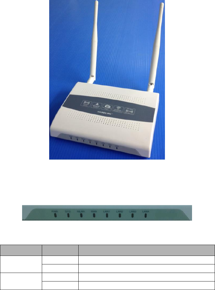
1-4 Outlook
Figure 1 Outlook
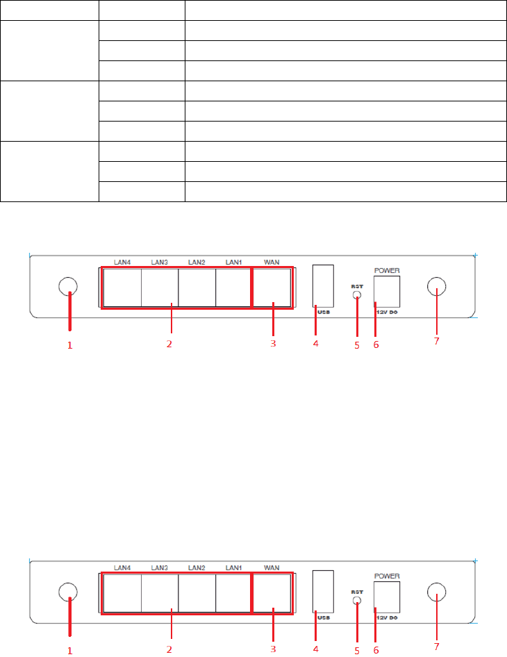
1-4-1 Front Panel
The front panel of the R-300NP is shown as below.
Figure 2 Front Panel
LED Indicators
LED
State
Description
PWR
Off
The device is not receiving electrical power.
On
The device is receiving electrical power.
SYS
Off
The device status is defective.
On
The device is up and running.
R-300NP
7
Blinking
During firmware upgrade, the system LED will be blinking.
WLAN
Off
The Wireless is not ready.
On
The device has established a valid wireless connection.
Blinking
The Wireless connection is active.
WAN
Off
The WAN is not connected.
On
The WAN has a valid 10/100Mbps network connection.
Blinking
The WAN is sending or receiving packet.
LAN-1~
LAN-4
Off
The LAN is not connected.
On
The LAN has a valid 10/100Mbps network connection.
Blinking
The LAN is sending or receiving packet.
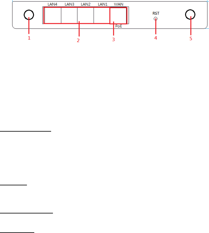
1-4-2 Rear Panel
The rear panel of R-300NP is shown as below.
Figure 3 R-300NP Rear Panel
1. Antenna
2. LAN Ports (1-4)
3. WAN/PoE port
4. USB
5. Reset
6. Power jack
7. Antenna
The rear panel of WG-701/WG-606 is shown as below.
Figure 4 R-300NP Rear Panel
1. Antenna
R-300NP
8
2. LAN Ports (1-4)
3. WAN Port
4. USB
5. Reset
6. Power jack
7. Antenna
The rear panel of AP-300NP is shown as below.
1. Antenna
2. LAN Ports (1-4)
3. WAN/PoE Port
4. Reset
5. Antenna
1-5 Technical Specifications
1-5-1 Hardware Specifications
Network Specification
IEEE802.3 10BaseT Ethernet
IEEE802.3u 100BaseTX Fast Ethernet
IEEE802.11g Wireless LAN
ANSI/IEEE 802.3 NWay auto-negotiation
Wi-Fi Compatible
Connectors
Four LAN Ports (10BaseT/100BaseTX Auto cross-over)
One WAN Port (10BaseT/100BaseTX Auto cross-over)
External Antenna Type
4dBi (Max) Dual detachable diversity antenna with reverse SMA
LED Indicators
One POWER LED

R-300NP
9
One WAN 10/100M Link/Activity LED
Four LAN 10M/100M Link/Activity LEDs
One Wireless Link/Activity LED
One System LED
Power Requirement
R-300NP:
External Power Adapter:
Power input: 12V, 1A
Power consumption: Under 5 Watts
PoE:
Power input: 48Vdc, 0.4A, IEEE 802.3at Compliance
Power consumption: Under 5 Watts
WG-701:
External Power Adapter:
Power input: 12V, 1A
Power consumption: Under 5 Watts
WG-606:
External Power Adapter:
Power input: 12V, 1A
Power consumption: Under 5 Watts
AP-300NP:
PoE:
Power input: 48Vdc, 0.4A, IEEE 802.3at Compliance
Power consumption: Under 5 Watts
Environment Conditions
Operating Temperature: 0 to 40°C
Storage Temperature: -10 to 60°C
Operating Humidity: 10~90% non-condensing
Storage Humidity: 10% to 90% non-condensing
Certifications
FCC,CE,NCC, BSMI,NTC(Thailand)
Dimension
Size:222 (L) x 143 (W) x 36 (H) mm
Weight: About 400 g (Net)
Mounting
Desktop, Wall mounted

R-300NP
10
1-5-2 Software Specifications
Networking
IP Plug and Play (iPnP)
WEP 64/128bit
WPA-PSA (TKIP)
WPA2-PSK(AES)
WPA/WPA2 Mix Mode-PSK (AES)
DHCP Server (RFC 2131)
Static IP WAN Client
DHCP WAN Client
PPPoE WAN Client (RFC 2516)
PPTP WAN Client
NAT (RFC 1631)
NTP (Network Time Protocol) Support
Wireless
Wireless IEEE802.11n
User Authentication
Facebook Authentication
Access Form
Security and Firewall
Layer 2 Isolation
SSL Administration
VPN Pass through (IPSec/PPTP/L2TP)
Pass through Destination IP/URL
Pass through Source IP/MAC
Restricted Destination Filtering IP/URL
Anti-DDOS
Management
Administrator / Front Desk Access Management
Access Control List Management (ACL)
Remote Browser-based Configuration and management
Firmware Upgrade (RFC 1350) via HTTP/TFTP
Backup/Restore/Factory Default Setting
Port Forwarding
R-300NP
11
System Information Table
Real-time Current User List / DHCP Clients List /
Session List / Account List
Syslog
Bandwidth control per device
Session control per device
Session Trace
SNMP (Read Only)
Ping Command

R-300NP
12
2 Installation
The followings are instructions for setting up the R-300NP. Refer to the illustration and follow the simple
steps below to quickly install your R-300NP.
2-1 Installation Requirements
Before installing the R-300NP, make sure your network meets the following requirements.
The R-300NP requires one of the following types of software:
Windows XP/Vista/7
Red Hat Linux 7.3 or later version
MAC OS X 10.2.4 or later version
Web Browser Software (Microsoft I.E or Firefox , Google Chrome)
One computer with an installed 10Mbps, 100Mbps or 10/100Mbps Ethernet card
UTP network Cable with a RJ-45 connection (Package contents)
Note:
1. The gateway’s default IP address setting is “10.59.1.1”.
2. The gateway’s default subnet mask setting is “255.255.255.0”.
R-300NP
13
2-2 Hardware Setup
1. Connect the R-300NP WAN port to modem by Ethernet cable.(Usually, the ISP will provide one
Ethernet cable along with the modem)
2. Connect the R-300NP LAN port to PC by Ethernet cable.
3. Install the antennas.
4. Plug in the power adapter. The R-300NP will be booted once the power is connected.
5. Check the LED status of SYS, WAN, LAN and WLAN, the network connection is valid if the LED
turned on.
R-300NP
14
3. Configuring the R-300NP
3-1 Wizard Setup
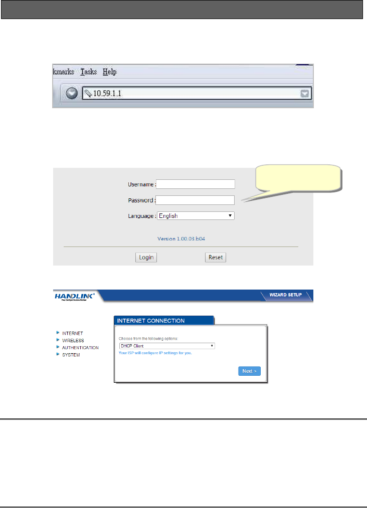
Step 1: Open your browser, and then enter the factory default IP address 10.59.1.1 in your browser’s
location box. Press Enter.
Figure 5 Web Browser
Step 2: The R-300NP login page will appear. Typing the factory default Username “admin” and
Password “admin” then click Login. If you are first time setting the system, the wizard setup
screen will appear as figure 7. You will be guided, step-by-step, through a basic setup
procedure.
Figure 6 R-300NP login page
Figure 7 Wizard Setup Screen
Note:
This Web agent is best viewed with IE 9.0 or Chrome and above browsers.
Username and Password can consist of up to 20 alphanumeric characters and are case sensitive.
If for some reason your password is lost or you cannot gain access to the R-300NP Configuration
Program, please press the reset button to load the device to manufacturer defaults.
If the R-300NP doesn’t send packet in 5 minutes (default), the R-300NP wills logout automatically.
Username: admin
Password: admin
R-300NP
15
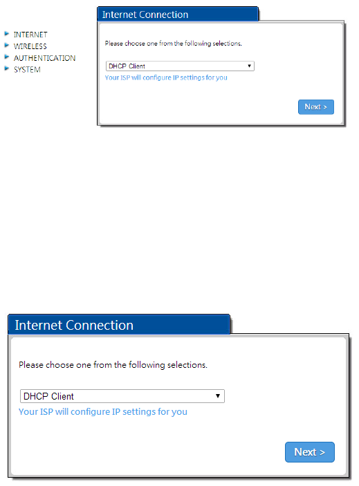
Step 3: Internet Connection Setting
Select the appropriate Internet connection type to connect to your ISP.
Figure 8 Internet Connection Setting Screen
DHCP Client
The device can work as a DHCP client. This allows the device to obtain the IP address and other
TCP/IP settings from your ISP. If your xDSL/Cable comes with this feature, please enable Use DHCP
Client.
Figure 9 Internet Connection Setting Screen—DHCP Client Setting
R-300NP
16
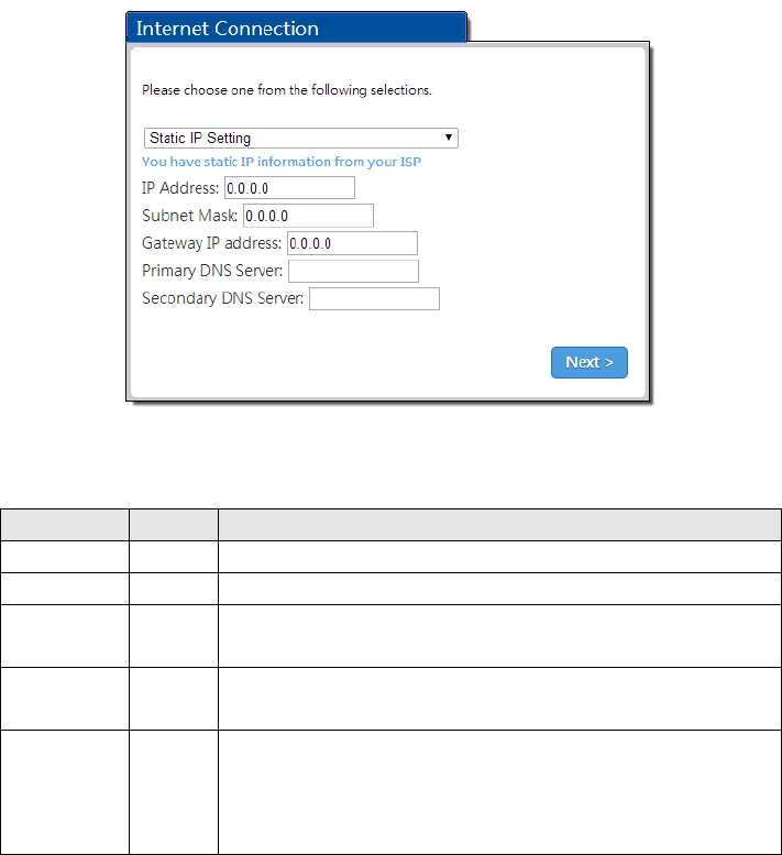
Static IP Setting
If Static IP Setting is selected, below setting screen will appear. Enter the IP address information
provided by your ISP.
Figure 10 Internet Connection Setting Screen—Static IP Setting
Item
Default
Description
IP Address
0.0.0.0
Enter the IP address provided by your ISP.
Subnet Mask
0.0.0.0
Enter the subnet mask for the IP address.
Gateway IP
Address
0.0.0.0
Enter the Gateway IP Address provided by your ISP.
Primary DNS
Server
Empty
Enter the primary DNS server IP address for the xDSL/Cable
connection (provided by your ISP).
Secondary
DNS Server
Empty
Enter the secondary DNS server IP address for the xDSL/Cable
connection (provided by your ISP). If the primary DNS Server IP were
not available, meanwhile, Secondary DNS Server IP would start in the
same time.
R-300NP
17
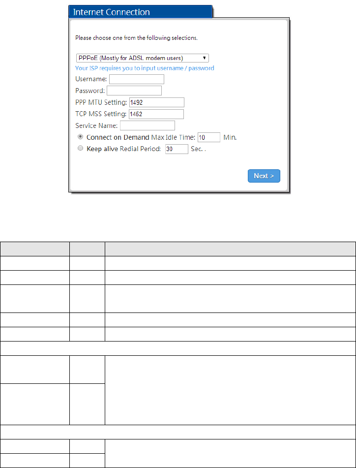
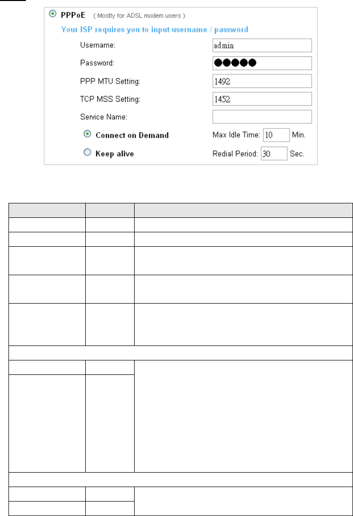
PPPoE (Mostly for ADSL modem users)
If “PPPoE” is selected, below setting screen will appear. Enter the username, password and other
major fields.
Figure 11 Internet Connection Setting Screen—PPPoE Setting
Item
Default
Description
Username
Empty
Enter the user name provided by your ISP.
Password
Empty
Enter the user password provided by your ISP.
PPP MTU Setting
1492
MTU (Maximum Transfer Unit) specifies maximum transmission unit
size.
TCP MSS Setting
1452
MSS (Maximum Segment Size) specifies maximum segment size.
Service Name
Empty
Enter the service name provided by your ISP.
Connect on Demand and Max Idle Time
Connect on
Demand
Enable
You can configure your R-300NP to cut your connection with your ISP
after a specified period of time (Max Idle Time). If you have been
disconnected due to inactivity, Connect on Demand enables your
R-300NP to automatically re-establish your connection as soon as you
attempt to access the Internet again
Max Idle Time
10 Min.
Keep alive and Redial Period
Keep alive
Disable
This option keeps your PPPoE enabled Internet access connected
indefinitely, even when it sits idle.
Redial Period
30 sec.
R-300NP
18
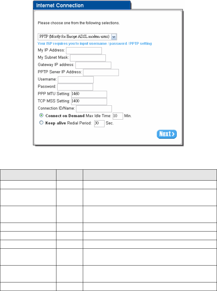
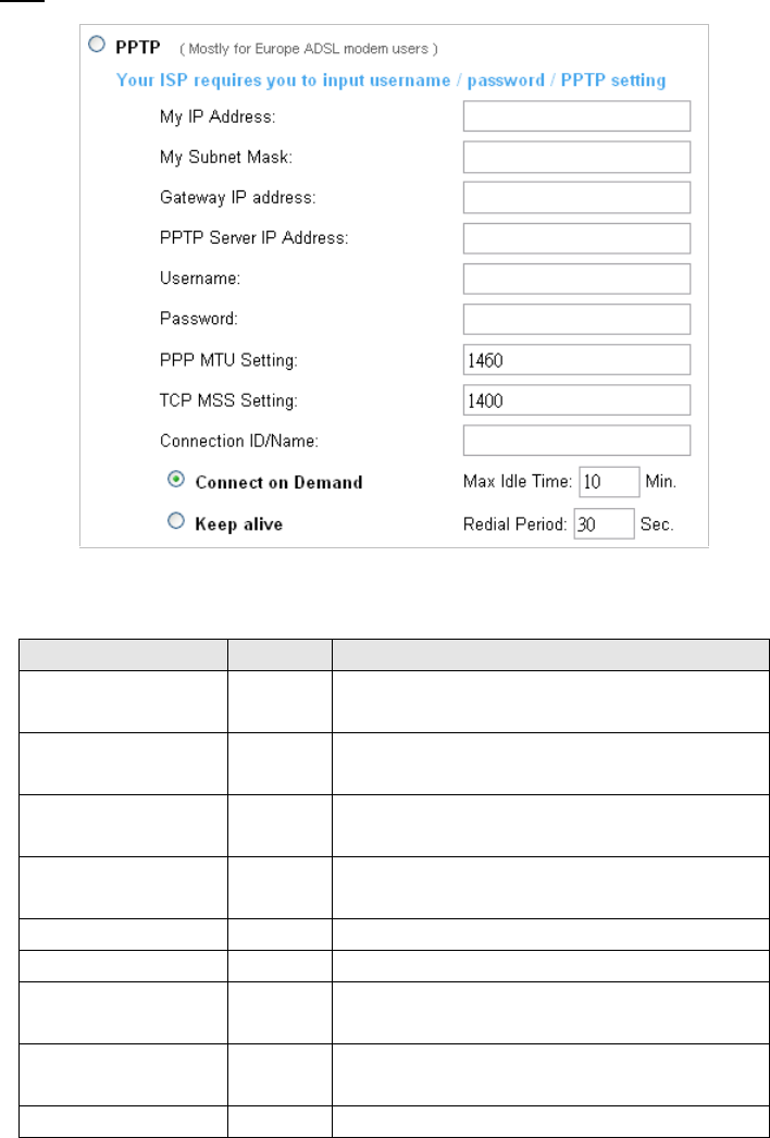
PPTP (Mostly for Europe ADSL modem users)
If “PPTP” is selected, then this screen will appear. Fill out all the information provided by your ISP.
Figure 12 Internet Connection Setting Screen—PPTP Client Setting
Item
Default
Description
My IP Address
Empty
Enter the PPTP local IP address provided by your ISP.
My Subnet Mask
Empty
Enter the PPTP local Subnet Mask IP address for the IP
address (My IP Address).
Gateway IP Address
Empty
Enter the PPTP server Gateway IP address provided by your
ISP.
PPTP Server IP Address
Empty
Enter the PPTP server IP address provided by your ISP.
Username
Empty
Enter the user name provided by your ISP.
Password
Empty
Enter the user password provided by your ISP.
PPP MTU Setting
1460
MTU (Maximum Transfer Unit) specifies maximum
transmission unit size.
TCP MSS Setting
1400
MSS (Maximum Segment Size) specifies maximum segment
size.
Connection ID/Name
Empty
Enter the connection ID or connection name.
R-300NP
19
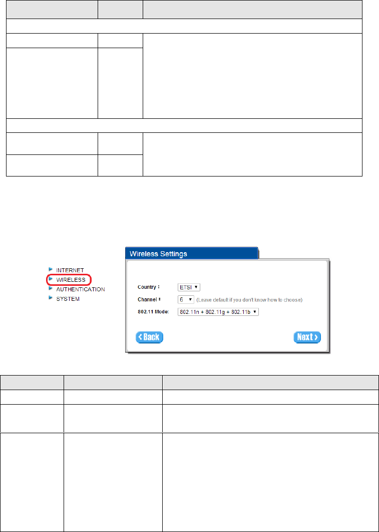
Step 4: Wireless Setting
This page allows you to define Country, Channel and 802.11 mode for wireless connection.
Figure 13 Wireless Setting Screen
Item
Default
Description
Country
ETSI
Select Wireless region you located.
Channel
6
Enter the channel ID for wireless connection. You could
choose from Ch1 to Ch11.
802.11 Mode
802.11n+802.11g+802.11b
Enter the 802.11 Mode for wireless connection
802.11n+802.11g+802.11b
802.11n+802.11g
802.11g+802.11b
802.11n only
802.11g only
802.11b only
Item
Default
Description
Connect on Demand and Max Idle Time
Connect on Demand
Enable
You can configure your R-300NP to cut your connection with
your ISP after a specified period of time (Max Idle Time). If
you have been disconnected due to inactivity, Connect on
Demand enables your R-300NP to automatically re-establish
your connection as soon as you attempt to access the
Internet again.
Max Idle Time
10 Minutes
Keep alive and Redial Period
Keep alive
Disable
This option keeps your PPTP enabled Internet access
connected indefinitely, even when it sits idle.
Redial Period
30 sec.
R-300NP
20
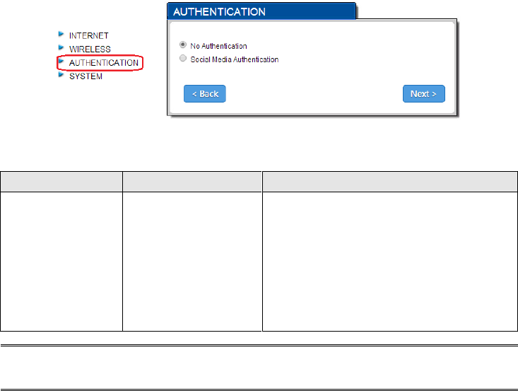
Step 5: Authentication Service Setting
Figure 14 Authentication Service Setting Screen
Note:
If you want to active Social Media Authentication by Coolbee WiFi, please refer to Appendix A.
Item
Default
Description
Authentication
No Authentication
No Authentication -
Subscriber can direct access to the Internet
without enter username and password.
Social Media Authentication -
R-300NP provides Built-in Authentication for
service provider to build up an Internet service
with Coolbee WiFi service.
R-300NP
21
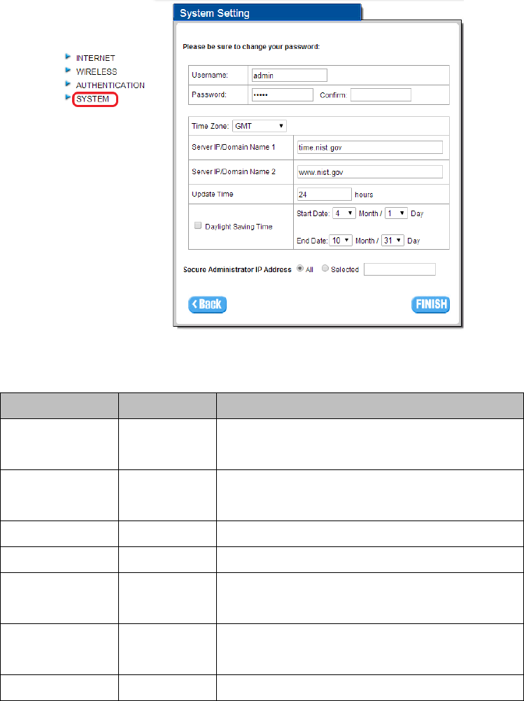
Step 6: System Setting
Figure 15 System Setting Screen
Item
Default
Description
Username
admin
Enter the user name. The user name can consist of up to
20 alphanumeric characters and is case sensitive.
Password
admin
Enter the user password. The password can consist of up
to 20 alphanumeric characters and is case sensitive.
Confirm
Empty
Enter the user password again to confirm the password.
Time Zone
GMT
Enter the Time Zone for the system.
Server IP/Domain
Name 1
time.nist.gov
Enter NTP Server IP or Domain
Server IP/Domain
Name 2
www.nist.gov
Enter NTP Server IP or Domain
Update Time
24 hours
Enter the number of hours for update time.
R-300NP
22
Daylight Saving
Time
Disable
The system time won’t be effected by daylight saving.
If you set the Daylight Saving Time (DST) on the R-300NP.
Please adjust the start date and end date.
Secure
Administrator IP
Address
All
This function allows remote user to management the
device. You can specify one or any IP addresses for
remote control the system.
Click ”FINISH” button to save the settings then the system will restart.
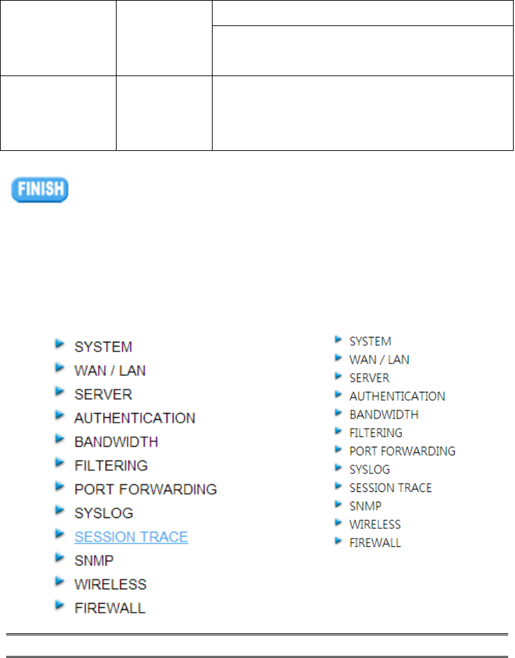
3-2 Advanced Setup
The Advanced Setup allows you to configure advanced settings related to accessing the Internet,
including,
1. SYSTEM
2. WAN / LAN
3. SERVER
4. AUTHENTICATION
5. BANDWIDTH
6. FILTERING
7. PORT FORWARDING
8. SYSLOG
9. SESSION TRACE
10. SNMP
11. WIRELESS
12. FIREWALL
Note: After change the settings of device, please click “Apply” button to save the new settings.
Figure 16 Advanced Setting Item Screen
R-300NP
23
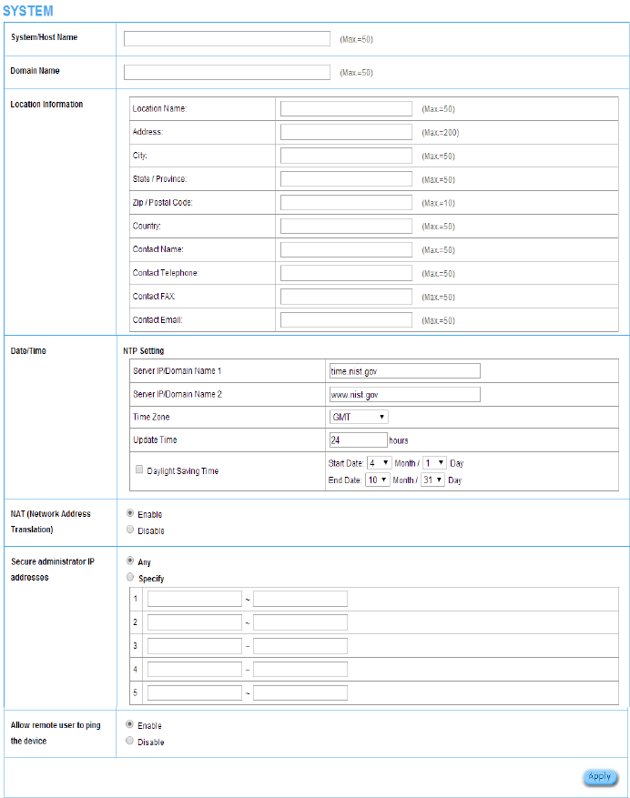
3-2-1 System
Define the R-300NP System configuration.
Figure 17 System Setting Screen
Figure 18 System Setting Screen

R-300NP
24
Item
Default
Description
System/Host Name
Empty
The system name can consist of up to 50
alphanumeric characters.
Domain Name
Empty
The Domain name can consist of up to 50
alphanumeric characters.
Location Information
Empty
Key in your location information.
Date/Time
NTP Setting
Disable
Enables or disables NTP (Network Time Protocol)
Time Server. Network Time Protocol can be utilized to
synchronize the time on devices across a network.
Server IP/Domain Name
Empty
Enter the IP address/domain name of NTP server.
Time Zone
GMT+8:00
Select the appropriate time zone for your location.
Update Time
24 hours
Enter the number of hours for update time.
Daylight Saving Time
Disable
Enables or disables Daylight Saving Time (DST).
Month/Day
Set the Daylight Saving Time (DST) on the R-300NP.
Adjust the start date and end date.
NAT (Network Address Translation)
NAT
Enable
Enables or disables NAT Address Translation function.
Secure administrator IP
Addresses
Any
Options: Any or Specify. Administrator can specify 5 IP
addresses or a range to allow remote control access
from network.
Allow remote user to ping the
device
Enable
This function allows remote user to ping the R-300NP
through Internet. Ping is normally used to test the
physical connection between two devices, to ensure
that everything is working correctly.
Click “Apply” button to save the new settings.
After click “Apply” button, the dialog box will appear as Figure. Click “back” button to back to previous
page.
Figure 19 Dialog Box
R-300NP
25
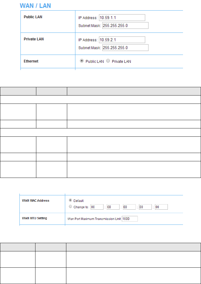
3-2-2 WAN/LAN
Device IP (LAN IP) Setting
Figure 20 Device IP (LAN IP) Setting
Item
Default
Description
Public LAN
IP Address
10.59.1.1
The internal LAN IP address of your Wireless Subscriber Server
Gateway for public LAN.
Subnet Mask
255.255.255.0
Enter the subnet mask for public IP address.
Private LAN
IP Address
10.59.1.1
The internal LAN IP address of your Wireless Subscriber Server
Gateway for private LAN.
Subnet Mask
255.255.255.0
Enter the subnet mask for private IP address.
Ethernet
Public LAN
You could choose which Ethernet to use for the internet
connection.
WAN MAC Address
Figure 21 WAN MAC Address Setting
Item
Default
Description
WAN MAC
Address
Default
The default MAC address is set to the WAN physical interface on
device.
WAN MTU
Setting
1500
You could set the MTU in this column.
R-300NP
26
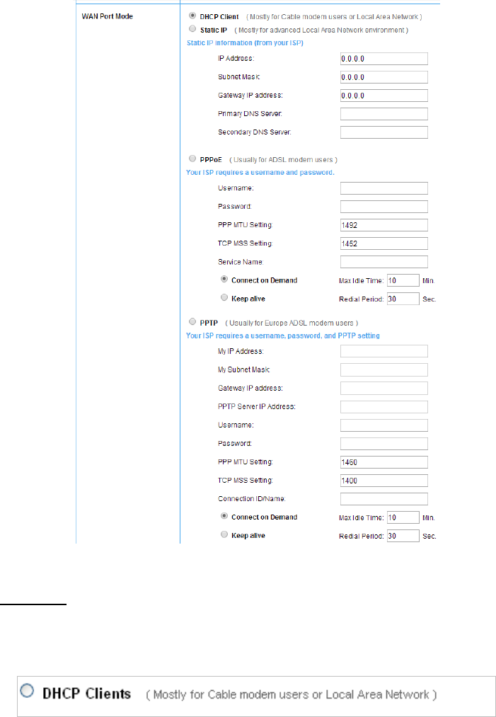
WAN Port Mode
Figure 22 WAN Port Mode Setting
DHCP Client
The device can work as a DHCP client. This allows the device to obtain the IP address and other
TCP/IP settings from your ISP. If your xDSL/Cable comes with this feature, please enable Use DHCP
Client.
Figure 23 DHCP Client Setting Screen
R-300NP
27
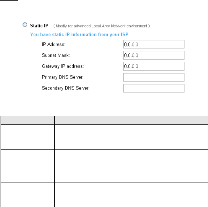
Static IP
If Static IP Setting is selected, this screen will appear. Enter the IP address information provided by
your ISP.
Figure 24 Static IP Setting Screen
Item
Description
IP Address
Enter the IP address for the xDSL/Cable connection (provided by your
ISP).
Subnet Mask
Enter the subnet mask for the IP address.
Gateway IP Gateway
Enter the Gateway IP address for the xDSL/Cable connection (provided by
your ISP).
Primary DNS Server
A primary DNS server IP address for the xDSL/Cable connection (provided
by your ISP).
Secondary DNS Server
A secondary DNS server IP address for the xDSL/Cable connection
(provided by your ISP). If the primary DNS Server IP were not available,
the secondary DNS Server IP would start in the same time.
R-300NP
28
PPPoE
Figure 25 PPPoE Setting Screen
Item
Default
Description
User Name
Empty
Enter your PPPoE account name
Password
Empty
Enter your PPPoE password..
PPP MTU Setting
1492
MTU (Maximum Transfer Unit) specifies maximum
transmission unit size.
TCP MSS Setting
1452
MSS (Maximum Segment Size) specifies maximum segment
size.
Service Name
Empty
Enter the service name provided by your ISP. The service
name can consist of up to 64 alphanumeric characters and is
case sensitive.
Connect on Demand and Max Idle Time
Connect on Demand
Enable
You can configure your R-300NP to cut your connection with
your ISP after a specified period of time (Max Idle Time). If
you have been disconnected due to inactivity, Connect on
Demand enables your R-300NP to automatically re-establish
your connection as soon as you attempt to access the
Internet again. If you wish to activate Connect on Demand,
click the radio button. If you want your Internet connection to
remain, click the radio button of keep alive.
Max Idle Time
10 Minutes
Keep alive and Redial Period
Keep alive
Disable
This option keeps your PPPoE enabled Internet access
connected indefinitely, even when it sits idle.
Redial Period
30 Seconds
R-300NP
29
PPTP
Figure 26 PPTP Setting Screen
Item
Default
Description
My IP Address
Empty
A PPTP local IP address for the xDSL/Cable connection
(provided by your ISP).
My Subnet Mask
Empty
Enter the PPTP local IP address for the xDSL/Cable
connection.
Gateway IP Address
Empty
A PPTP local default gateway for the xDSL/Cable
connection (provided by your ISP).
PPTP Server IP Address
Empty
Enter the PPTP server IP address for the xDSL/Cable
connection (provided by your ISP).
Username
Empty
Enter your PPTP account name.
Password
Empty
Enter your PPTP password.
PPP MTU Setting
1460
MTU (Maximum Transfer Unit) specifies maximum
transmission unit size.
TCP MSS Setting
1400
MSS (Maximum Segment Size) specifies maximum
segment size.
Connection ID/Name
Empty
Enter the connection ID or connection name.
R-300NP
30
Connect on Demand and Max Idle Time
Connect on Demand
Enable
You can configure your R-300NP to cut your connection
with your ISP after a specified period of time (Max Idle
Time). If you have been disconnected due to inactivity,
Connect on Demand enables your R-300NP to
automatically re-establish your connection as soon as
you attempt to access the Internet again. If you wish to
activate Connect on Demand, click the radio button. If
you want your Internet connection to remain, click the
radio button of keep alive.
Max Idle Time
10 Minutes
Keep alive and Redial Period
Keep alive
Disable
This option keeps your PPTP enabled Internet access
connected indefinitely, even when it sits idle.
Click “Apply” button to save the new settings.
After click “Apply” button, the dialog box will appear as below. Click “back” button to go back to
previous page.
Figure 27 Dialog Box
R-300NP
31
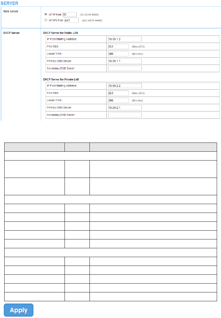
3-2-3 Server
Figure 28 Server Setting Screen
Item
Default
Description
Web Server
HTTP Port
80
Enter the HTTP port number. The HTTP port allowed
range is 80 or 8010 to 8060.
HTTPS Port
443
Enter the HTTPS port number. The HTTPS port allowed
range is 443 or 4430 to 4440.
DHCP Server for Public LAN
IP Pool Starting Address
10.59.1.2
Enter the DHCP Pool Starting IP address for Public LAN
Pool Size
253
The DHCP pool size range is 1 to 253.
Lease Time
300
The DHCP lease time.
Primary DNS Server
168.95.1.1
Enter the IP address of primary DNS server.
Secondary DNS Server
Empty
Enter the IP address of secondary DNS server.
DHCP Server for Private LAN
IP Pool Starting Address
10.59.2.2
Enter the DHCP Pool Starting IP address for Private LAN
Pool Size
253
The DHCP pool size range is 1 to 253.
Lease Time
300
The DHCP lease time.
Primary DNS Server
168.95.2.1
Enter the IP address of primary DNS server.
Secondary DNS Server
Empty
Enter the IP address of secondary DNS server.
Click “Apply” button to save the new settings.
R-300NP
32
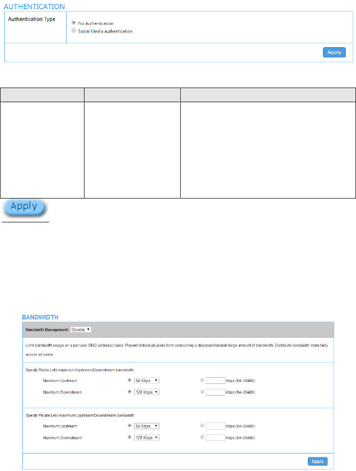
3-2-4 Authentication
Figure 29 Authentication Setting Screen
Click
“
Apply
”
button to save the new settings.
3-2-5 Bandwidth
The function enables administrator to limit bandwidth usage on per user basis (MAC address). That
prevents users from consuming a disproportionately large amount of bandwidth. Every user gets a fair
share of the available bandwidth.
Figure 30 Bandwidth Setting Screen
Item
Default
Description
Authentication
No Authentication
No Authentication -
Subscriber can direct access the Internet without
enter username and password.
Social Media Authentication -
R-300NP provides Built-in Authentication for
service provider to build up an Internet service
with Coolbee WiFi service.

R-300NP
33
Item
Default
Description
Bandwidth
Disable
Enables or disables Bandwidth Management.
Specify Public LAN maximum Upstream/Downstream bandwidth:
Maximum Upstream
64Kbps
Specify the amount of upstream bandwidth.
You can set the range by drop list:64K, 128K, 256K, 384K, 512K,
1.5Mbps, 3Mbps, 5Mbps, 10Mbps and 20 Mbps.
Or key in by yourself, the range is from 64 ~20480Kbps
Maximum Downstream
128Kbps
Specify the amount of downstream bandwidth.
You can set the range by drop list:64K, 128K, 256K, 384K, 512K,
1.5Mbps, 3Mbps, 5Mbps, 10Mbps and 20 Mbps.
Or key in by yourself, the range is from 64 ~20480Kbps
Specify Private LAN maximum Upstream/Downstream bandwidth:
Maximum Upstream
64Kbps
Specify the amount of upstream bandwidth.
You can set the range by drop list:64K, 128K, 256K, 384K, 512K,
1.5Mbps, 3Mbps, 5Mbps, 10Mbps and 20 Mbps.
Or key in by yourself, the range is from 64 ~20480Kbps
Maximum Downstream
128Kbps
Specify the amount of downstream bandwidth.
You can set the range by drop list:64K, 128K, 256K, 384K, 512K,
1.5Mbps, 3Mbps, 5Mbps, 10Mbps and 20 Mbps.
Or key in by yourself, the range is from 64 ~20480Kbps
R-300NP
34
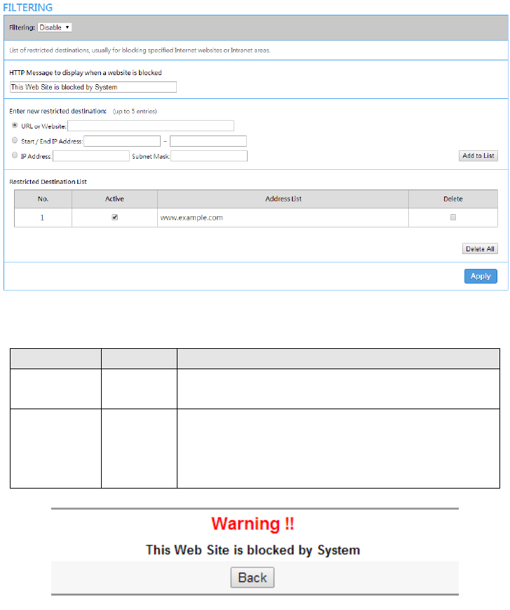
3-2-6 Filtering
Filtering allows the administrator to have a list of restricted destinations, which is useful to block
specified Internet websites or Intranet areas.
Figure 31 Filtering Setting Screen
Item
Default
Description
Filtering
Disable
Enables or disables filtering function. It could be set up to 5
entries.
HTTP Message
to display when a
website is
blocked
The Web Site
is blocked by
System
Enter the http message. The maximum character of the HTTP
message is 200. The warning page show as Figure 32.
Figure 32 Warning screen
R-300NP
35
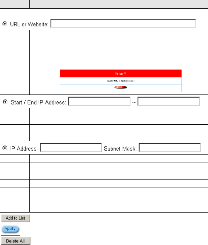
Item
Default
Description
Restrict Destination
URL or
Website
Empty
Enter the URL Page of you wants to filter; please use this format such like
“http://www.yahoo.com”. The maximum character of the URL Page is 50.
If the URL format is wrong, the system will show the error message as
below.
Start IP
Address
Empty
Enter the start IP address of you wants to filter.
End IP
Address
Empty
Enter the end IP address of you wants to filter.
IP Address
Empty
Enter the destination IP address of you wants to filter.
Subnet Mask
Empty
Enter the destination subnet mask.
No
-
The index number of filtering address.
Active
Disable
Click on check box, active or inactive the filtering address.
Address List
-
Display the filtering address(s).
Delete
Disable
Select the check boxes and click ‘Delete’ to delete the filtering
address(s).
Click “Add to List” button to add a new entry.
Click “Apply” button to save the new settings.
Click “Delete All & Apply” button to delete all entries.
R-300NP
36
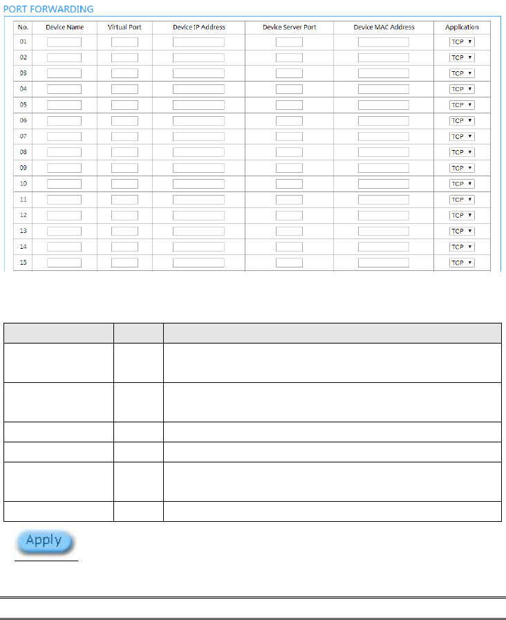
3-2-7 Port forwarding
Administrator can set an entry of R-300NP which translating the address or port number of a packet to
a new destination
Figure 33 Port Forwarding Setting Screen
Item
Default
Description
Device Name
Empty
The LAN device name. The system could support up to 20 date at
one time.
Virtual Port
0
The virtual port number valid range is 60001 to 60050 or 5900 to
5910.
Device IP Address
Empty
Enter the IP address of LAN device in the format “xxx.xxx.xxx.xxx”
Device Server Port
0
Enter the server port of LAN device.
Device MAC Address
Empty
The MAC address of LAN device. For input the device MAC
address, please use this format such as”0050BA8D2296”.
Application
TCP
Select one protocol type of LAN device by clicking in the list box.
Click “Apply” button to save the new settings.
Note: The system does not support FTP.
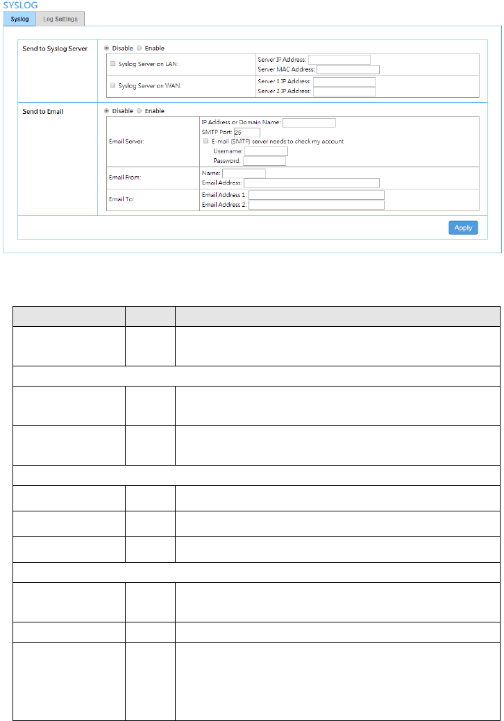
3-2-8 Syslog
The function allows the device to transmit event messages to your syslog server or your email address
R-300NP
37
for monitoring and troubleshooting.
Figure 34 Syslog Setting Screen
Syslog Setting
Item
Default
Description
Send to Syslog
Server
Disable
Enables or disables the syslog server function.
Syslog on LAN
Server IP Address
Empty
Enter syslog server’s IP address. The R-300NP will send all of its
logs to the specified syslog server.
Server MAC Address
Empty
Enter the syslog server’s MAC address. The R-300NP will send
all of its logs to the specified syslog server.
Syslog on WAN
Server 1 IP Address
Empty
Enter IP address of first syslog server.
Server 2 IP Address
Empty
Enter IP address of second syslog server.
Send to Email
Disable
Enables or disables the send to e-mail function.
E-mail Server
IP Address or Domain
Name
Empty
Enter the SMTP server IP address or domain name. The
maximum allowed characters length is 50.
SMTP Port
25
The SMTP port allowed range is 25 or 2500 to 2599.
E-mail (SMTP) Server
needs to check my
account
Disable
If your SMTP server requires authentication before accepting
e-mail, please enable this check box. The username and
password are supplied by your network administrator, SMTP
server provider or ISP.
R-300NP
38
Username
Empty
Enter the username for the SMTP server.
Password
Empty
Enter the password for the SMTP server
Email From
Name
Empty
Enter the name you would like to appear in the “message from”
field of your outgoing message. The maximum allowed
characters length is 20.
Email Address
Empty
Enter your e-mail address. This is the address others will use to
send email to Email Address 1/Email Address 2.
Email To
Disable
Enables or disables the send to e-mail function.
Email Address 1
Empty
Enter your first e-mail address to receive the logs.
Email Address 2
Empty
Enter your second e-mail address to receive the logs.
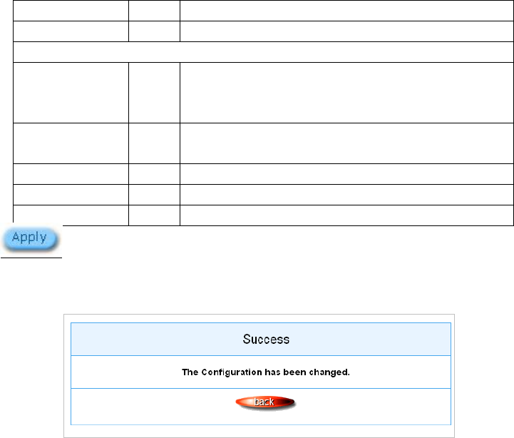
Click “Apply” button to save the new settings.
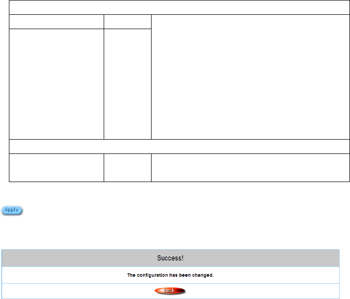
After click “Apply” button, the dialog box will appear as below. Click “Back” button to return to Syslog
setting screen.
Figure 35 Success Dialog Box
R-300NP
39
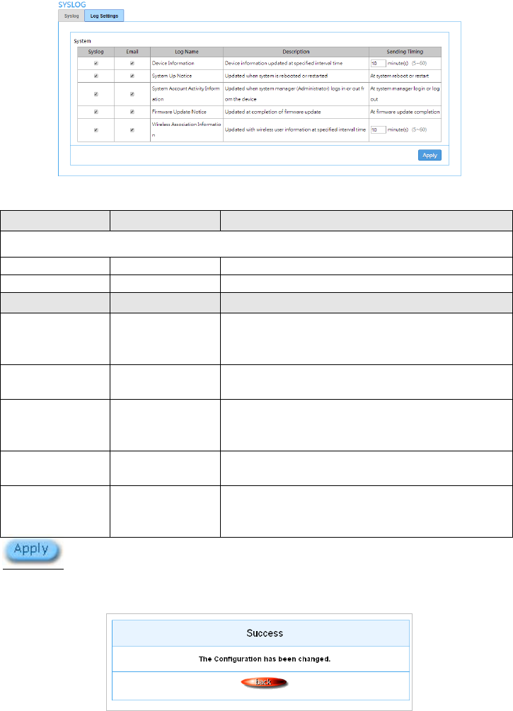
Log Settings
Figure 36 Log Settings Screen
Click “Apply” button to save the new settings.
After click “Apply” button, the success dialog box will appear. Click “Back” button to return to Logs
setting screen.
Figure 37 Success Dialog Box
Item
Default
Description
System
Syslog
Unchecked
If checked, the log data will be sent by syslog.
Email
Unchecked
If checked, the log data will be sent by e-mail.
Item
Interval Time
Description
Device Information
10 minutes
The log included system information would be sent
according to specified interval time. The time could be set
from 5 to 60 minutes.
System Up Notice
When system
rebooted or restarted
If device have been rebooted or restarted, the log will be
sent.
System Account
Activity Information
When system
manager login or
logout
A log will be sent if system manager (Administrator) login
to or logout from the device
Firmware Update
Notice
When firmware
update completed
A log will be sent if firmware update completed
Wireless Association
Information
10 minutes.
A log including wireless users information will be sent
according to specified interval time. The time could be set
from 5 to 60 minutes.
R-300NP
40
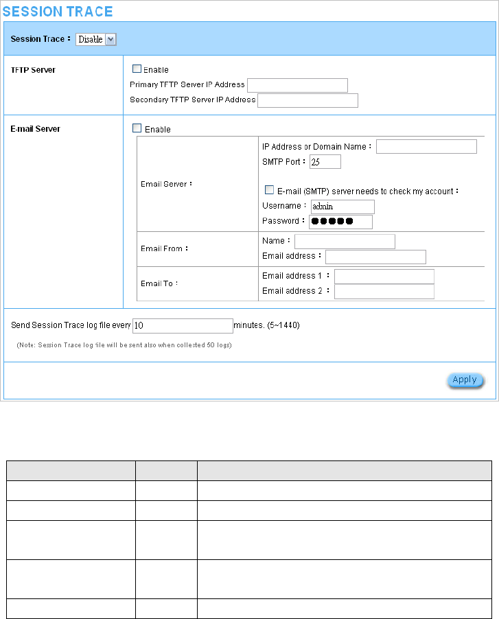
3-2-9 Session Trace
Session Trace is an intelligent function to help service provider to trace every user’s access behavior.
When “session trace” is enable , the system will collect information such like destination IP, destination
port, source IP, source MAC, source port by every user and send the collected information in text
format file to specified TFTP server or Email Server.
Figure 38 Session Trace Setting Screen
Item
Default
Description
Session Trace
Disable
Disables or enables session trace function.
TFTP Server
Disable
Disables or enables this function
Primary TFTP Server IP
Address
Empty
Enter the IP address of the primary TFTP server.
Secondary TFTP Server
IP Address
Empty
Enter the IP address of the second TFTP server.
E-mail Server
Disable
Disables or enables this function

R-300NP
41
Send to Email
Disable
Enables or disables the send to e-mail function.
IP Address or Domain
Name
Empty
Enter the SMTP server IP address or domain name. The
maximum allowed characters length is 50.
SMTP Port
Empty
The SMTP port allowed range is 25 or 2500 to 2599.
E-mail (SMTP) Server
needs to check my
account
Disable
If your SMTP server requires authentication before
accepting e-mail, click on check box. These values
(username and password) are supplied by your network
administrator, SMTP server provider or ISP.
Username
Empty
Enter the username for the SMTP server.
Password
Empty
Enter the password for the SMTP server
Email From
Name
Empty
Enter the name you would like to appear in the “message
from” field of your outgoing message. The maximum
allowed characters length is 20.
Email Address
Empty
Enter your e-mail address. This is the address others will
use to send email to Email Address 1/Email Address 2.
Email To
Email Address 1
Empty
Enter your first e-mail address to receive the logs.
Email Address 2
Empty
Enter your second e-mail address to receive the logs.
Send Session Trace log
file every~ minutes.
10 minutes
The field means to send the session trace log file every
interval minutes. The value range is 5 to 1440 (minutes).
R-300NP
42
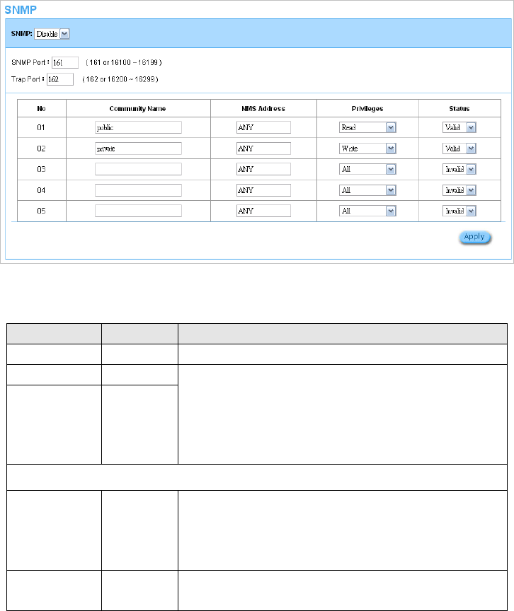
3-2-10 SNMP
The SNMP Agent Configuration screen enables you to access to your device via Simple Network
Management Protocol. If you are not familiar with SNMP, please consult your Network Administrator or
consult SNMP reference material. You must first enable SNMP on the SNMP Agent Configuration
screen.
Figure 39 SNMP Setting Screen
Item
Default
Description
SNMP
Disable
Disables or enables the SNMP management.
SNMP Port
161
If the SNMP enables, also allowed to specific the SNMP port
number via NAT. The allowed SNMP port numbers are 161
(default), 16100-16199 and Trap port numbers are 162 (default),
16200-16299. This Port setting is useful for remote control via
NAT network.
Trap Port
162
Configuration
Community Name
public/private
Every unit with SNMP enable must be configured to recognize
one or more community. The default setting for the community of
entry 1 is “public” and for the entry 2 is “private” and others are
empty.
NMS Address
ANY
The address of the NMS. The default settings for the NMS
Networking are “ANY”.
R-300NP
43
Item
Default
Description
Privileges
Read/Write
Choose “Read”, “Write”, “Trap Recipients” and “All” for different
privileges. The default setting of the entry 2 is “write” and others
are “read”.
Status
Valid/Invalid
Chosen “Valid” or “Invalid”. The default setting of entry 1, 2 are
valid and others are invalid.
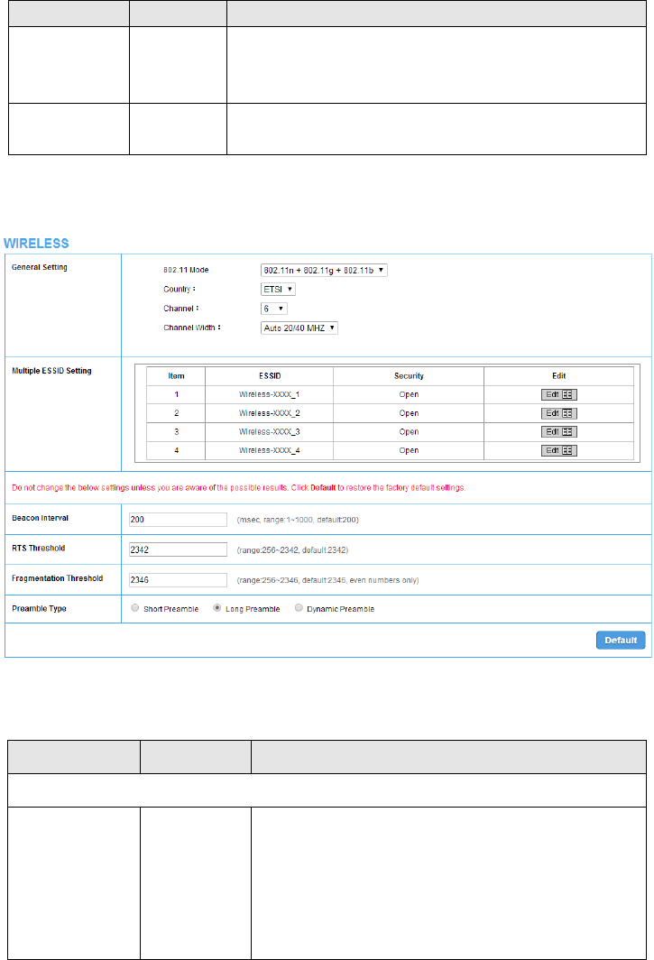
3-2-11 Wireless
Figure 40 Wireless Setting Screen
Item
Default
Description
General Settings
802.11 Mode
802.11n+802.11
g+802.11b
Choose one:
-802.11n+802.11g+802.11b
-802.11n+802.11g
-802.11g+802.11b
-802.11n only
-802.11g only
-802.11b only

R-300NP
44
Country
ETSI
Wireless Region. You could choose “ETSI” or “FCC”.
Channel
6
Select the channel ID for wireless connection.
Channel Width
Auto 20/40 MHZ
You could chose “Auto 20/40 MHZ” or “20 MHZ”
Multiple ESSID Setting
ESSID
Wireless-XXXX
_1 ~4
The R-300NP has 4 ESSID. The ESSID is the unique name
that is shared among all points in a wireless network. It is
case sensitive and must not exceed 32 characters. Click
“Edit”, then you can configure more detail of ESSID settings.
The default ESSID name is Wireless-XXXX_1(to 4) “XXXX” is
the last 4 digit of R-300NP WLAN MAC.
Beacon Interval
200
This value valid range is 1 to 1000 indicates the frequency
interval of the beacon.
RTS Threshold
2342
This value valid range is 256-2342. This setting determines
the packet size at which the R-300NP issues a request to
send (RTS) before sending the packet. A low RTS Threshold
setting can be useful in areas where many client devices are
associating with the R-300NP, or in areas where the clients
are far apart and can detect only the R-300NP and not each
other.
Fragmentation
Threshold
2346
This setting determines the size at which packets are
fragmented. Enter a setting ranging from 256 to 2346 bytes.
Use a low setting in areas where communication is poor or
where there is a great deal of radio interference.
Preamble Type
Long Preamble
The preamble type is a section of data at the head of a
packet that contains information the R-300NP and client
devices need when sending and receiving packets. The
setting menu allows you to select a long, short or dynamic
preamble type.
R-300NP
45
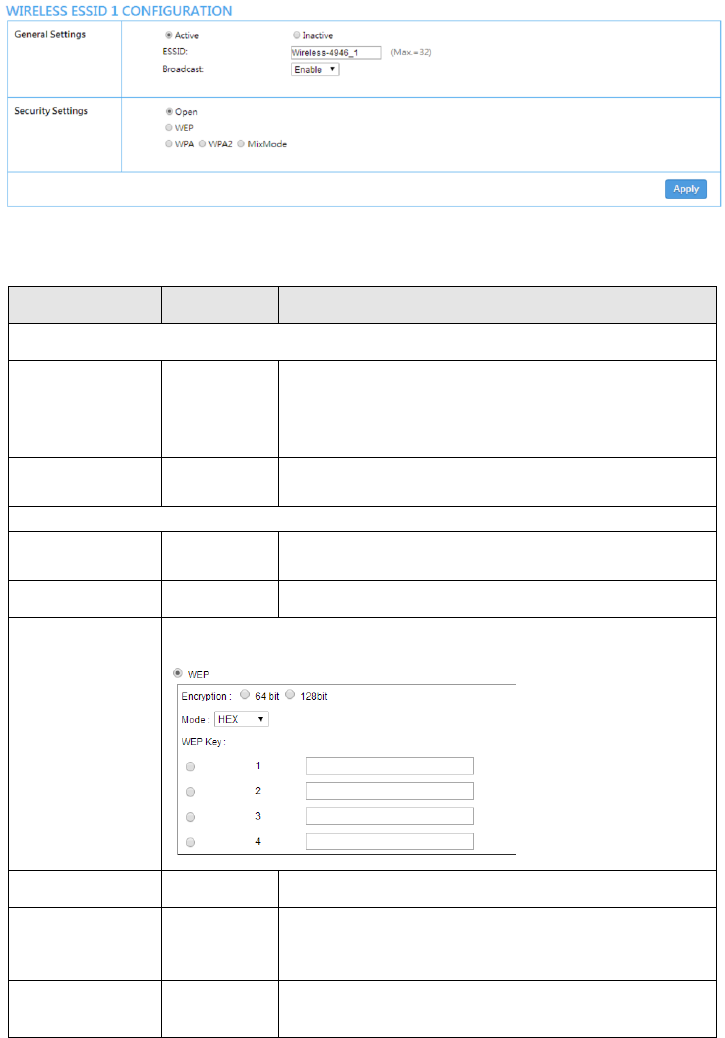
Edit the ESSID
Figure 41 Wireless ESSID Setting Screen
Item
Default
Description
General Settings
ESSID
Active
You could set active or inactive for any ESSID.
The ESSID is the unique name that is shared among all
points in a wireless network. It is case sensitive and must not
exceed 32 characters.
Broadcast
Enable
a method of transferring a message to all recipients
simultaneously
Security Settings
Security Settings
Open
This allows you to setting if there’s any data encryption will be
and what kind of encryption you would like to use.
Open
Data will transit without any data encryption.
WEP Encryption
Wired Equivalent Privacy Encryption
Encryption
64 bit
The R-300NP supports 64-bit or 128 bit WEP encryption.
Mode
HEX
Options: HEX (Hexadecimal) and ASCII (American Standard
Code for Information Interchange).
WEP Key
1
This selects which of the Keys that R-300NP uses when it
transmits. You can change the selected encryption key any
R-300NP
46
time to increase the security of your network.
Note: You have to configure all WEP keys (1~4), and select
one of the WEP key you would like to use this time.
Enter 5 characters for ASCII 64-bit WEP Key.
Enter 10 characters for Hex 64-bit WEP Key.
Enter 13 characters for ASCII 128-bit WEP Key.
Enter 26 characters for Hex 128-bit WEP Key.
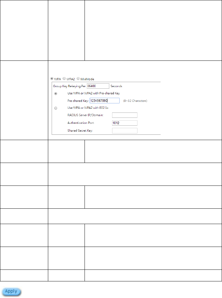
WPA ,WPA2 and
Mix mode
Encryption
Wi-Fi Protected Access Encryption
Group Key
Re-Keying
86400 Seconds
Enter a number in the field to set the force re-keying interval.
Use WPA with
Pre-shared Key
Enable
Pre-Shared Key
1234567890
Enter a pre-shared key from 8 to 32 case sensitive ASCII
characters.
Use WPA with
RADIUS
Disable
Server IP
Empty
Enter the RADIUS server IP address or domain name. The
maximum allowed characters length is 15.
Authentication Port
1812
Enter the authentication port number. The allowed numbers
are from 0 to 65535.
Share Secret Key
Empty
Enter the RADIUS secret key
Click “Apply” button to save the new settings.
R-300NP
47
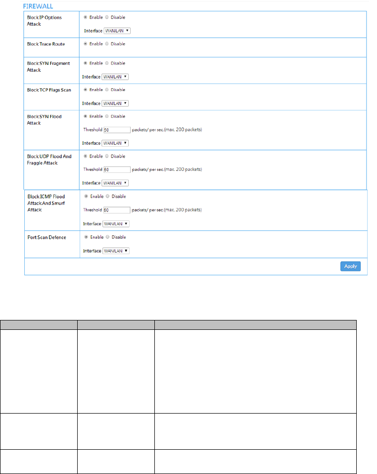
3-2-12 Firewall
A firewall protects your network against threats from the public Internet. Here you can enable or
disable R-300NP’s firewall.
Figure 42 Firewall Setting Screen
Item
Default
Description
Block IP Options
Attack
Enable
WAN/LAN
The R-300NP will ignore any IP packets with IP option
field in the datagram header. The reason for limitation
is IP option appears to be a vulnerability of the security
because it will carry significant information, such as
security, closed user group parameters, a series of
Internet addresses, routing messages...etc.
Interface: WAN/LAN, WAN, LAN
Block Trace Route
Enable
The R-300NP will not forward any trace route packets
if you enable this item.
Block SYN
Fragment Attack
Enable
WAN/LAN
The R-300NP will drop any packets that having SYN
flag and having mote fragment setting if you enable

R-300NP
48
this item.
Interface: WAN/LAN, WAN, LAN
Block TCP Flags
Scan
Enable
WAN/LAN
Any TCP packet with anomaly flag setting will be
dropped if you enable this item. Those scanning
activities include no flag scan, FIN without ACK scan,
SYN FIN scan, Xmas scan and full Xmas scan.
Interface: WAN/LAN, WAN, LAN
Block SYN Flood
Attack
Enable
50 packets/ per sec
WAN/LAN
Enable the SYN flood defense function to prevent the
TCP SYN packets’ attempt to exhaust the
limited-resource of R-300NP. Once the TCP SYN
packets exceeded the defined value, the R-300NP will
start to discard the subsequent TCP SYN packets.
Interface: WAN/LAN, WAN, LAN
Block UDP Flood
And Fraggle
Attack
Enable
50 packets/ per sec
WAN/LAN
Once the UDP packets exceeded the defined value,
the R-300NP will start to discard the subsequent UDP
packets.
Interface: WAN/LAN, WAN, LAN
Block ICMP Flood
Attack And Smurf
Attack
Enable
50 packets/ per sec
WAN/LAN
Similar to the UDP flood defense function, once the
thresholds of ICMP packets have exceeded the
defined value, the R-300NP will discard the ICMP echo
requests coming from the Internet.
And R-300NP will also ignore any broadcasting ICMP
echo request.
Interface: WAN/LAN, WAN, LAN
Port Scan Defence
Enable
WAN/LAN
Enables/disables R-300NP from responding to
Internet based port scans. This feature is designed to
protect your private local network from Internet based
hackers who attempt to gain unsolicited access your
network by detecting open IP ports on R-300NP.
Interface: WAN/LAN, WAN, LAN
R-300NP
49
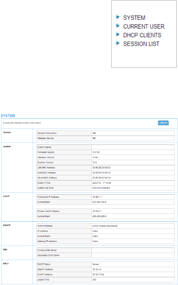
3-3 System Status
Display R-300NP system basic status, including,
1. System
2. Current User
3. DHCP Clients
4. Session List
Figure 43 System Status Item Screen
3-3-1 System
The System Information Menu displays current system basic information including the service
connection message, host name, LAN, WAN, DHCP Configuration, DNS, E-mail Redirection, SSL
Certificate, network traffic Information and the system firmware version.
Figure 44 System Status Screen
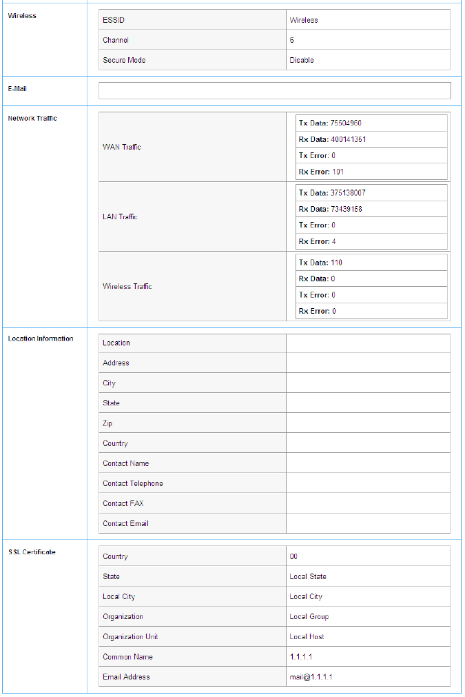
R-300NP
50
Figure 45 System Status Screen
R-300NP
51
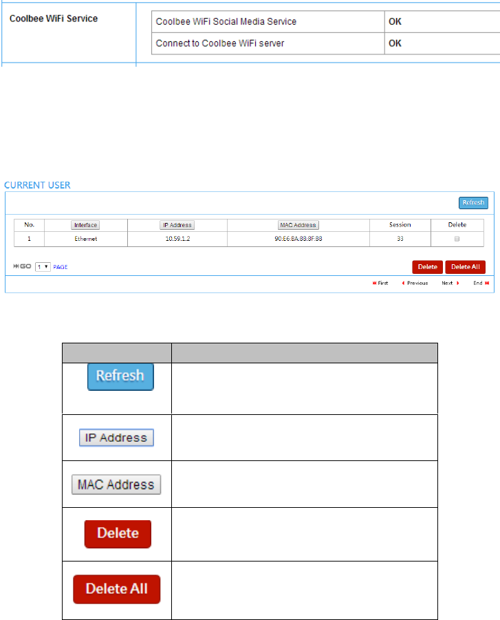
R-300NP connect to Coolbee WiFi service
If you R-300NP have registered on Coolbee WiFi and have been switch to Coolbee WiFi mode(Social
Media Authentication enable), you will see the status of Coolbee WiFi on the top of the system page as
below.
Figure 46 System Status Screen
3-3-2 Current User
Display the current logged-in subscribers’ status. It allows the service provider to disconnect any
subscribers.
Figure 47 Current User List (No Authentication)
Item
Description
Click on refresh button to update the current user
list page.
Click the column button to sort the column in
ascending/descending order.
Click the column button to sort the column in
ascending/descending order.
Select the check boxes and click “Delete” to
delete accounts.
Delete all accounts in current user list.
R-300NP
52
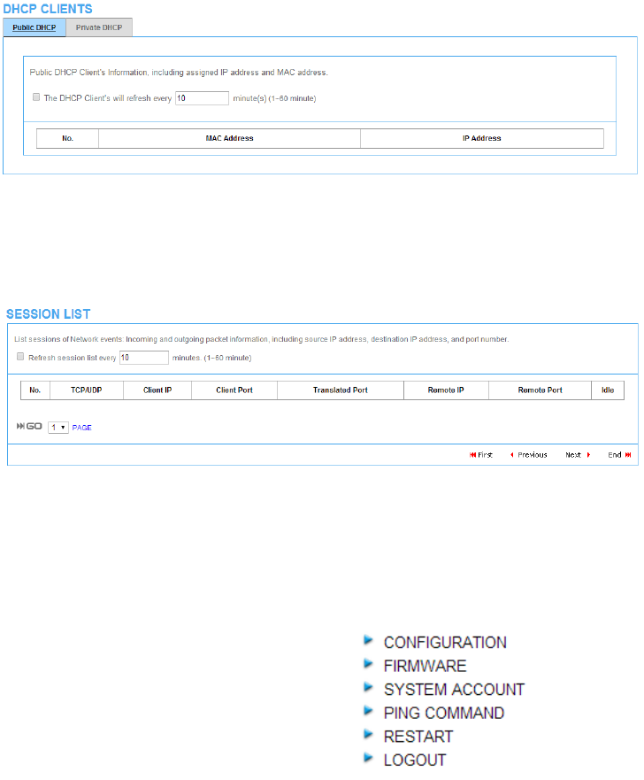
3-3-3 DHCP Clients
The DHCP client table shows the current DHCP users for both Public DHCP and Private DHCP.
Figure 48 Current User Screen
3-3-4 Session List
The administrator could remote monitor the real time usage status of R-300NP via this page.
Figure 49 Session List Screen
3-4 System Tools
This allows service provider or administrator to process Firmware upgrade, change password and
backup or restore configuration.
1. CONFIGURATION
2. FIRMWARE
3. SYSTEM ACCOUNT
4. PING COMMAND
5. RESTART
6. LOGOUT
Figure 50 System Tools Item
R-300NP
53
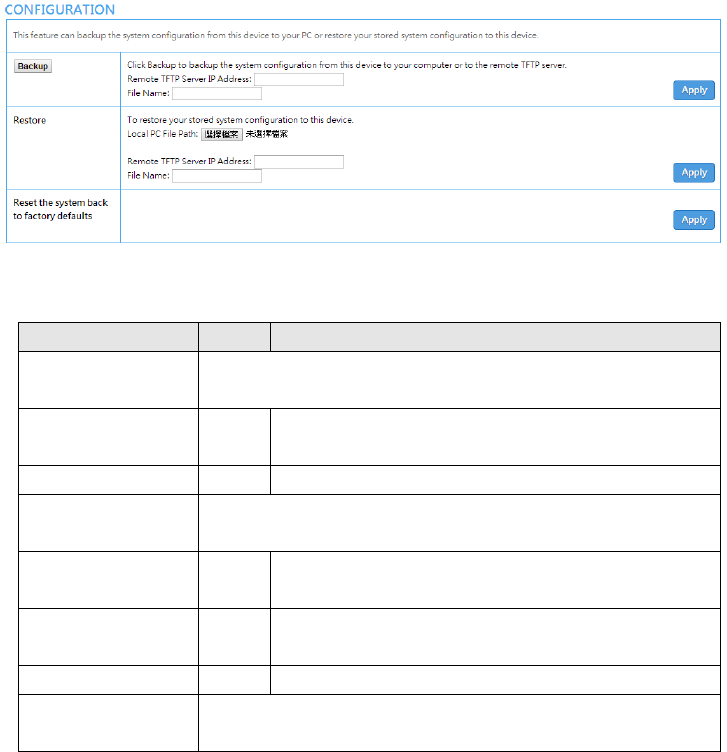
3-4-1 Configuration
Use the Configuration item to save, restore or reset configuration parameters of the R-300NP.
Figure 51 Configuration Setting Screen
Item
Default
Description
Backup
Click it to save the system configuration to your computer. (The default
file name is “export.cfg” ) or it could be save to the TFTP you assigned.
Remote TFTP Server IP
Address
Empty
Enter the IP address of TFTP Server that you would like to
store the system backup file.
File Name
Empty
Enter the file name for the system backup file.
Restore
Click it to restore your system configuration, you could choose the file
from your computer or TFTP server.
Local PC File Path
Empty
Enter the file pathname of the system configuration file in the
Local PC File Path field.
Remote TFTP Server IP
Address
Empty
Enter the IP address of TFTP Server where the system
configuration file is stored.
File Name
Empty
Enter the file name that you use to restore the system.
Reset the system back
to factory defaults
Click it to erase all setting and back to factory default.
R-300NP
54
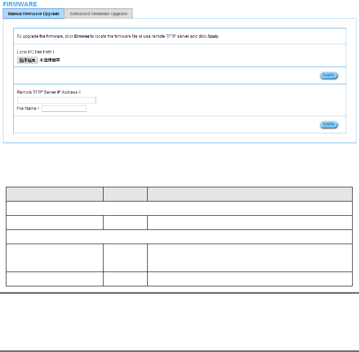
3-4-2 Firmware
This function allows you to upgrade the firmware of your R-300NP.
Manual Firmware Upgrade
Figure 52 Manual Firmware Upgrade Setting Screen
Item
Default
Description
This allow administrator to upgrade the firmware via local file.
Local PC File Path
Empty
Select the file from local PC.
This allows administrator use TFTP server to upgrade firmware.
Remote TFTP Server IP
Address
Empty
Enter the IP address of TFTP Server.
File Name
Empty
Enter the file name in the File Name field.
Note:
1. Before downloading the new firmware, users must save the configuration file for restore
configuration parameters of the device.
2. Do not remove power during the upgrade process. This will damage the unit.
R-300NP
55
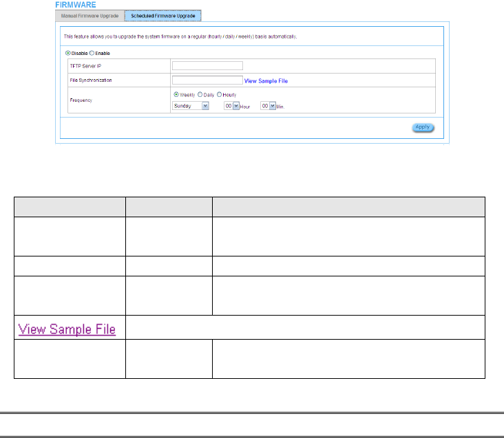
Scheduled Firmware Upgrade
Scheduled Firmware Upgrade is a program that enables an automatic upgrade to the latest firmware
version through the TFTP server.
Figure 53 Scheduled Firmware Upgrade Setting Screen
Item
Default
Description
Disable/Enable
Disable
Disable or enable the scheduled firmware upgrade
function.
TFTP Server IP
Empty
Enter the IP address of TFTP Server.
File Synchronization
Empty
Enter the file name and location in the File
Synchronization field.
Click the button to display synchronization file example.
Frequency
Weekly
Set the firmware upgrade time. The default value is
“Weekly”.
Note: Do not turn the power off during the upgrade process. This will damage the unit.
R-300NP
56
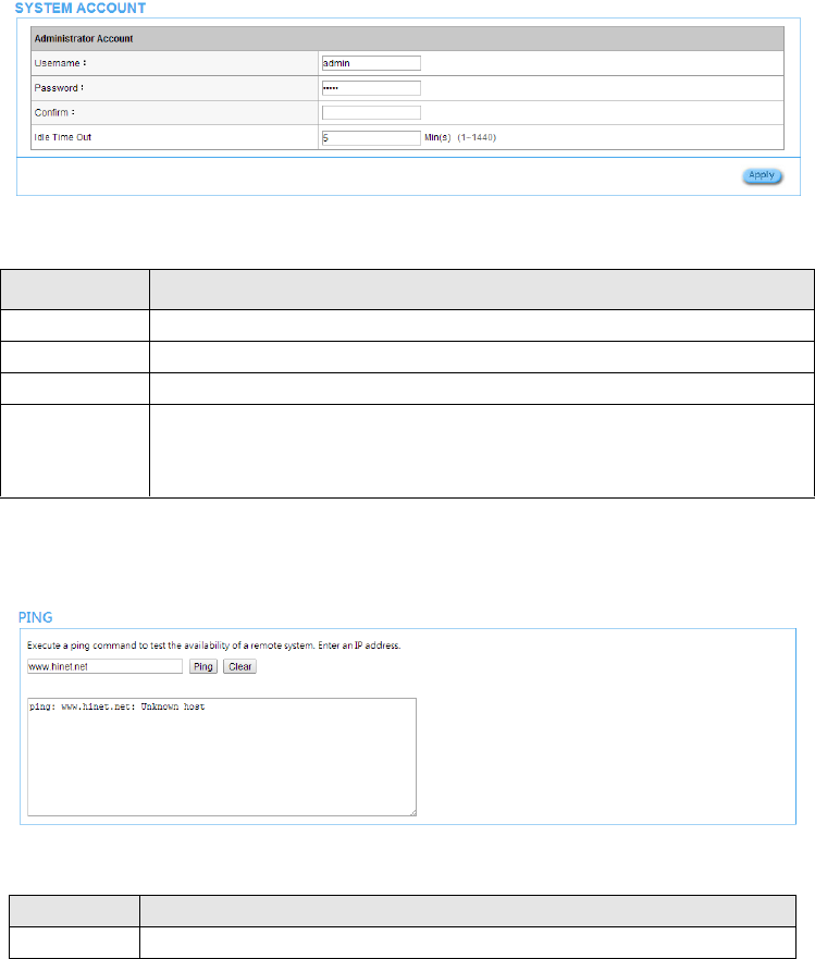
3-4-3 System Account
Use the System Account screen to change the administrator setting.
Figure 54 System Account Setting Screen
3-4-4 PING Command
The Ping function can check the R-300NP networking connect status.
Figure 55 Ping Command Screen
Item
Description
Username
The username can consist of up to 20 alphanumeric characters and is sensitive.
Password
The password can consist of up to 20 alphanumeric characters and is sensitive.
Confirm
The password for confirmation.
Idle Time Out
The user idle time out valid is 1 to 1440 minutes. If the idle time out is set as 5
minutes, it means if the account doesn’t send packet in 5 minutes, the account will
logout automatically.
Item
Description
IP or URL
Enter the IP address or the URL link of the unit that you would like to check.
R-300NP
57
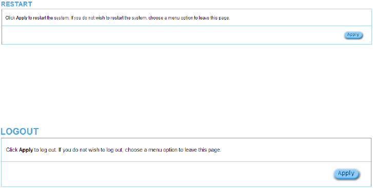
3-4-5 Restart
If your R-300NP is not running normally, you can choose this option to restart R-300NP. Click the
“Apply” button to restart the R-300NP with all of your settings remaining the same.
Figure 56 Restart Screen
3-4-6 Logout
If you would like to leave the configuration page, please click “Apply” to exit.
Figure 57 Logout Screen

R-300NP
58
Appendix A Regulations/EMI Compliance
FCC Warning statement
For FCC 15b devices
This equipment has been tested and found to comply with the limits for a Class B digital device,
pursuant to part 15 of the FCC rules. These limits are designed to provide reasonable protection
against harmful interference in a residential installation. This equipment generates, uses and can
radiate radio frequency energy and, if not installed and used in accordance with the instructions, may
cause harmful interference to radio communications. However, there is no guarantee that interference
will not occur in a particular installation. If this equipment does cause harmful interference to radio or
television reception, which can be determined by turning the equipment off and on, the user is
encouraged to try to correct the interference by one or more of the following measures:
Reorient or relocate the receiving antenna.
Increase the separation between the equipment and receiver.
Connect the equipment into an outlet on a circuit different from that to which the receiver is
connected.
Consult the dealer or an experienced radio/TV technician for help.
You are cautioned that changes or modifications not expressly approved by the party responsible for
compliance could void your authority to operate the equipment.
This device complies with Part 15 of the FCC Rules. Operation is subject to the following two conditions:
(1) this device may not cause harmful interference and (2) this device must accept any interference
received, including interference that may cause undesired operation
FCC RF Radiation Exposure Statement
1. This Transmitter must not be co‐located or operating in conjunction with any other antenna or
transmitter.
2. This equipment complies with FCC RF radiation exposure limits set forth for an uncontrolled
environment. This equipment should be installed and operated with a minimum distance of 20
centimeters between the radiator and your body.

R-300NP
59
NCC Statement
低功率射頻電機設備警語
依據低功率電波輻射性電機管理辦法
第十二條
經型式認證合格之低功率射頻電機,非經許可,公司、商號或使用者均不得擅自變更頻率、加大功
率或變更原設計之特性及功能。
第十四條
低功率射頻電機之使用不得影響飛航安全及干擾合法通信;經發現有干擾現象時,應立即停用,並
改善至無干擾時方得繼續使用。
前項合法通信,指依電信法規定作業之無線電通信。
低功率射頻電機須忍受合法通信或工業、科學及醫療用電波輻射性電機設備之干擾。
NTC Thailand:
“This telecommunication equipment conforms to NTC technical requirement.”

R-300NP
60
Appendix D LIMITED WARRANTY
What the warranty covers:
We warrant its products to be free from defects in material and workmanship during the warranty
period. If a product proves to be defective in material or workmanship during the warranty period,
we will at its sole option repair or replace the product with a like product. Replacement product or
parts may include remanufactured or refurbished parts or components.
How long the warranty is effective:
The Easy Hotspot Kit is warranted for one year for all parts and one year for all labor from the date
of the first consumer purchase.
Who the warranty protects:
This warranty is valid only for the first consumer purchaser.
What the warranty does not cover:
1. Any product, on which the serial number has been defaced, modified or removed.
2. Damage, deterioration or malfunction resulting from:
a. Accident, misuse, neglect, fire, water, lightning, or other acts of nature, unauthorized product
modification, or failure to follow instructions supplied with the product.
b. Repair or attempted repair by anyone not authorized by us.
c. Any damage of the product due to shipment.
d. Removal or installation of the product.
e. Causes external to the product, such as electric power fluctuations or
failure.
f. Use of supplies or parts not meeting our specifications.
g. Normal wears and tear.
h. Any other cause that does not relate to a product defect.
3. Removal, installation, and set-up service charges.
R-300NP
61
How to get service:
1. For information about receiving service under warranty, contact our Customer Support.
2. To obtain warranted service, you will be required to provide (a) the original dated sales slip, (b)
your name, (c) your address, (d) a Description of the problem and (e) the serial number of the
product.
3. Take or ship the product prepaid in the original container to your dealer, and our service center.
4. For additional information, contact your dealer or our Customer Service Center.
Limitation of implied warranties:
THERE ARE NO WARRANTIED, EXPRESSED OR IMPLIED, WHICH EXTEND BEYOND THE
DESCRIPTION CONTAINED HEREIN INCLUDING THE IMPLIED WARRANTY OF
MERCHANTABILITY AND FITNESS FOR A PARTICULAR PURPOSE.
Exclusion of damages:
OUR LIABILITY IS LIMITED TO THE COST OF REPAIR OR REPLACEMENT OF THE PRODUCT.
We SHALL NOT BE LIABLE FOR:
1. DAMAGE TO OTHER PROPERTY CAUSED BY ANY DEFECTS IN THE PRODUCT,
DAMAGES BASED UPON INCONVENIENCE, LOSS OF USE OF THE PRODUCT, LOSS OF
TIME, LOSS OF PROFITS, LOSS OF BUSINESS OPPORTUNITY, LOSS OF GOODWILL,
INTERFERENCE WITH BUSINESS RELATIONSHIPS, OR OTHER COMMERCIAL LOSS,
EVEN IF ADVISED OF THE POSSIBLITY OF SUCH DAMAGES.
2. ANY OTHER DAMAGES, WHETHER INCIDENTAL, CONSEQUENTIAL OR OTHERWISE.
3. ANY CLAIM AGAINST THE CUSTOMER BY ANY OTHER PARTY.