HandyWave HPS Wireless Serial Transceiver User Manual HPS Manual
HandyWave Co., Ltd. Wireless Serial Transceiver HPS Manual
UserManual.wiki
>
HandyWave
>
HPS User Manual
users manual
Navigation menu
Upload a User Manual
Namespaces
Wiki Guide
HTML
PDF
Info
Views
User Manual
Discussion / Help
Navigation
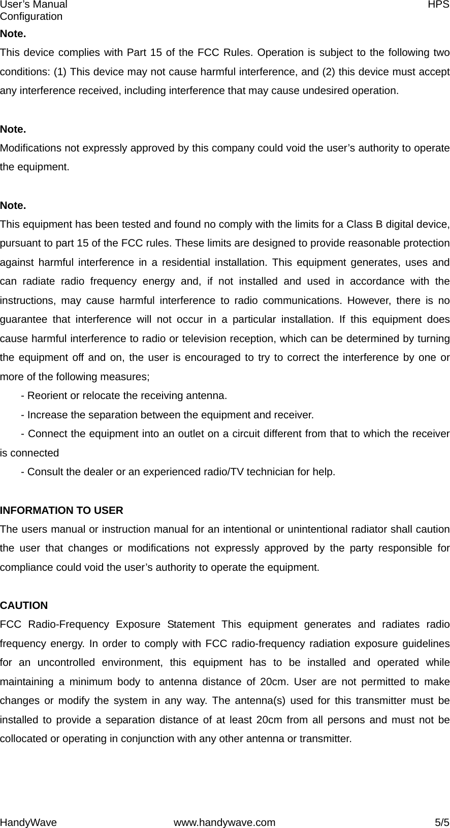
![User’s Manual HPS Configuration HandyWave www.handywave.com 4/5 Configuration You can change the configuration of HandyPort using HyperTerminal or similar terminal emulator. HyperTerminal Settings z COM Port Settings: 9600 8-N-1, Flow Control: None (Factory Settings of HandyPort) z Emulation: VT100 Switch Location To configure the HandyPort, the switch location shall be in RS-232. Start Configurations Step 1: Make a RS-232 connection between the PC and HandyPort. And supply power for HandyPort. Step 2: Open a Hyper Terminal at the PC and set it up. Step 3: Push the RST button on HandyPort. If you enter the configuration mode successfully, LNK LED will be flashing every second. Step 4: Hit the <Enter> key, 5 second later. Step 5: Change the configuration of HandyPort with commands, if necessary. Usage Printing If you are in the configuration mode, type “?<Enter>” for listing commands. If you want to know the usage of specific command, type “?[command]<Enter>”. All commands and parameters are case sensitive. Therefore, you have to use the capital letter for commands and parameters. End Configurations After finishing the configuration, you have to execute a command “X” to apply changes and exit the configuration mode. Frequently Used Commands Command Syntax Description A ABD_ADDR<CR> Change the remote device address B BBR[D]<CR> Change the baud rate M MMode<CR> Change the connection mode P PPA[D]<CR> Change the parity bit S SST[D]<CR> Change the stop bits V V Display the device information](https://usermanual.wiki/HandyWave/HPS/User-Guide-768639-Page-4.png)