HandyWave HPS-110 2.4GHz Transceiver Module User Manual Manual
HandyWave Co., Ltd. 2.4GHz Transceiver Module Manual
UserManual.wiki
>
HandyWave
>
HPS 110 User Manual
Manual
Navigation menu
Upload a User Manual
Namespaces
Wiki Guide
HTML
PDF
Info
Views
User Manual
Discussion / Help
Navigation

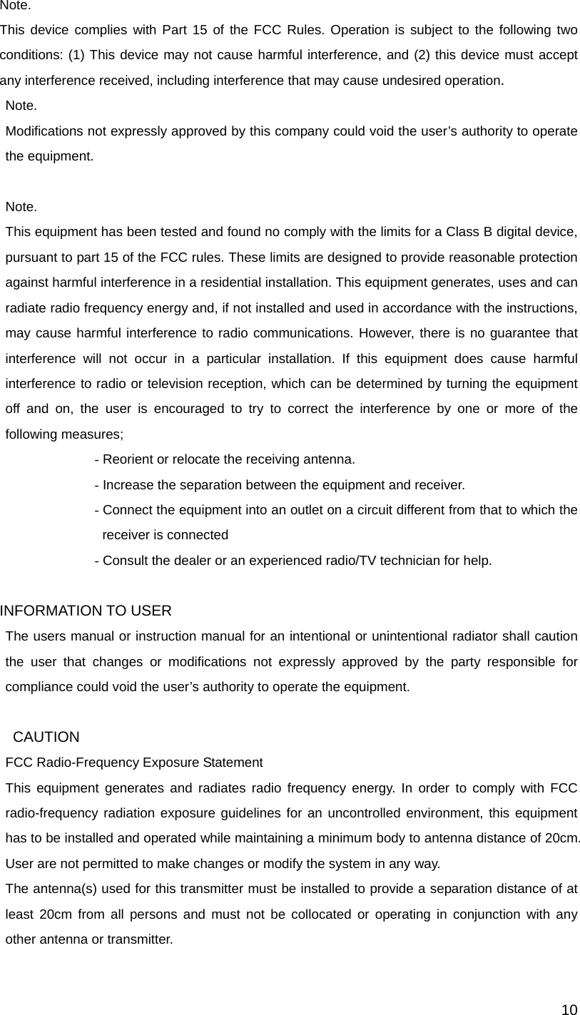
![73. Usage You can change the configuration of HPS-110 using Hyper Terminal1. 3.1. Hardware Installation Step 1: Assemble a provided antenna to HPS-110 body. Step 2: Plug a HPS-110 into the COM port of device. Step 3: Power on. Step 4: Configure the HPS-110, if necessary. 3.2. Hyper Terminal Settings Baud Rate: 9600 bps / Data Bit: 8 / Parity Bit: None / Stop Bit: 1 / Flow Control: None / Emulation: VT100 3.3. Configuration 3.3.1. Starting Configuration Step 1: Plug a HPS-110 into a COM port of PC. And Power it on. Step 2: Open a Hyper Terminal and set it up. Step 3: Push the RST button on HPS-110. If you enter the configuration mode successfully, LNK LED will be flashing every second. Step 4: Hit the <Enter> key, 5 second later. Step 5: Change the configuration of HPS-110 with commands, if necessary. 3.3.2. Usage Printing If you are in the configuration mode, type “?<Enter>” for listing of commands. If you want to know the usage of a command, type “?[command]<Enter>”. All commands and parameters are case sensitive. And you cannot use a <Backspace>. 3.3.3. After Configuration After finishing the configuration, you have to execute a command “X” to apply changes. 1 This manual is required the software version 2.0 or above.](https://usermanual.wiki/HandyWave/HPS-110/User-Guide-530161-Page-7.png)
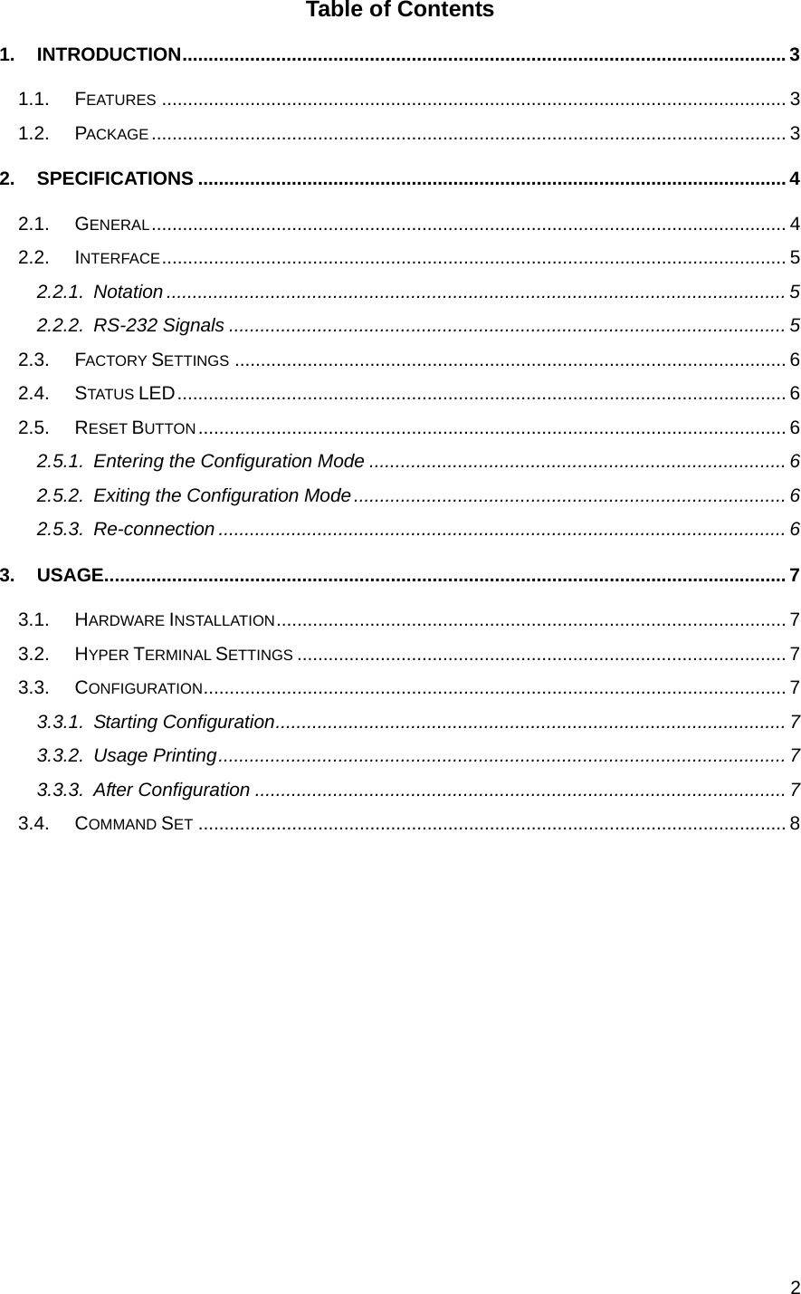
![83.4. Command Set The commands are as follows1: Item Syntax Description Remarks 1. Connecting address AAddr<CR> Set a remote device address for a wireless connection. A local and remote BD_ADDR always need to be difference. 2. Baud rate BBR[D]<CR> Change the baud rate. D (option): Change a factory setting2. Baud Rate (BR) - 0: 1200, 1: 2400, 2: 4800, 3: 9600, 4: 19200, 5: 38400, 6: 57600, 7: 115200 3. COM port CCOMPort<CR> Change a request serial port. COMPort: ‘1’ ~ ‘7’ Only valid in connection mode 2. 4. PIN code EPIN<CR> Authentication Off: hit <Enter> Authentication On: Type up to 11 characters Paired adapters should have a same PIN code. 5. Search timer GTO<CR> Set a search timeout. TO (timeout): ASCII ‘0’ ~ “999” Connection mode 3 only. Default: 10 sec. 6. Max number of search HNO<CR> Set the max number of search. NO: ASCII ‘0’ ~ “999” Connection mode 3 only. Default: 10 7. Search device ITO,NO[L]<CR> Execute searching devices. TO: ASCII ‘0’ ~ “999” NO: ASCII ‘0’ ~ “999” L (option): Display a long form. Connection mode 3 only. ‘,’: ASCII 0x2C 8. Discovery mode JE/D<CR> Set the discovery mode. ‘E’: Enable ‘D’: Disable Connection mode 1 only. Default: Enable 9. Low Power Mode KE/D<CR> Set the low power mode. ‘E’: Enable ‘D’: Disable Default: Disable 1 If you push the RST button, the COM port of HPS-110 will be stored the factory settings. 2 If you change a factory setting for baud rate, you have to remember it.](https://usermanual.wiki/HandyWave/HPS-110/User-Guide-530161-Page-8.png)
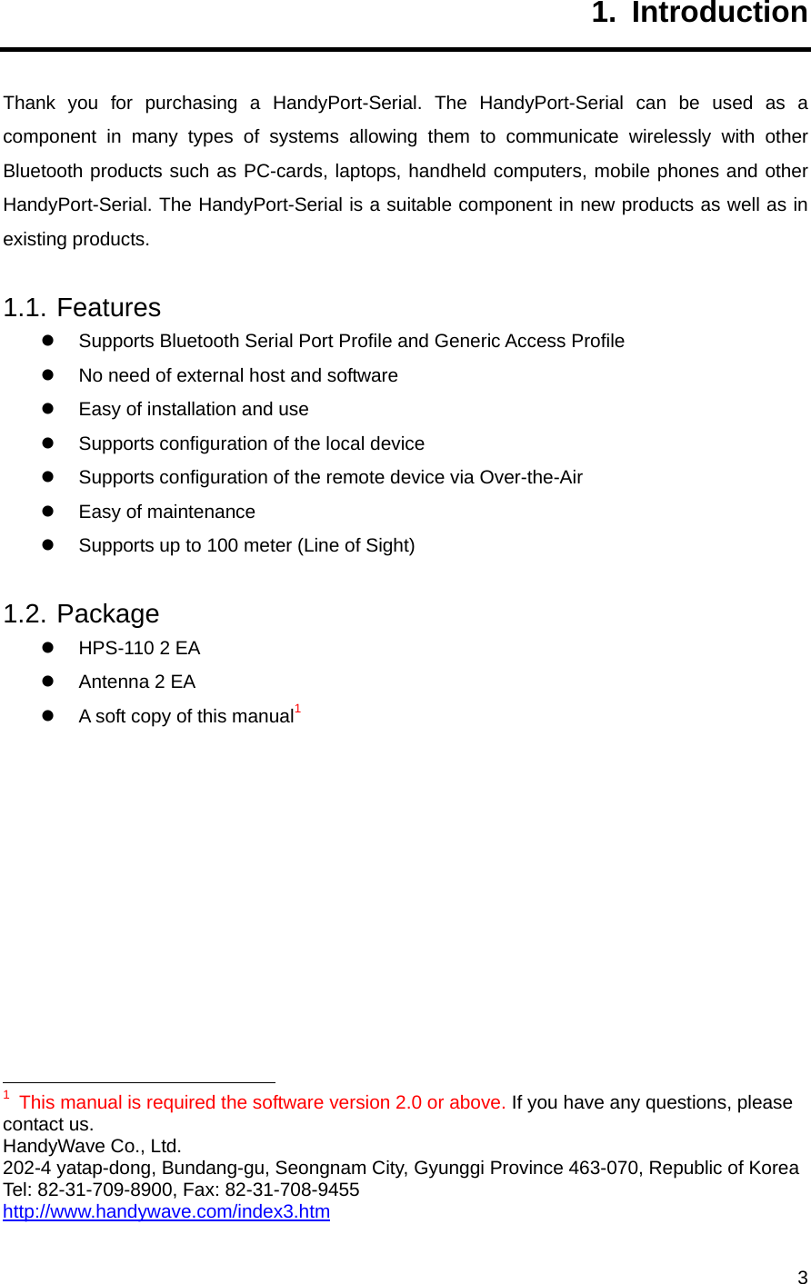
![910. Connection mode MMode<CR>1 Set a connection mode. Mode: ‘0’ – ‘3’ Mode 0 & 2: Required a remote address. Mode 2: Required a serial port. 0: 1:1 Mode 1: WAIT Mode 2: REGISTER and CONNECT Mode 3: WAIT Command Mode 11. Friendly name NName<CR> Set a friendly name up to 11 characters. 12. Parity Bit PPA[D]2<CR> Set the parity bit. D (option): Change a factory setting3. 0: None, 1: Odd 2: Even 13. Connection Timeout QTO<CR> Set the connection timeout.TO: ASCII ‘0’ ~ “999” Connection mode 3 only. Default: 10 sec. 14. Stop Bit SST[D]<CR> Set the stop bit. D (option): Change a factory setting4. 0: 1 Stop, 1: 2 Stop 15. Connect TAddr[,TO]<CR> Try to make a connection. Addr: a remote address TO (option): ASCII ‘0’ ~ “999” Connection mode 3 only. ‘,’: ASCII 0x2C Default Timeout: 10 sec. 16. Cancel U Cancel a command. Connection mode 3 only. 17. View V Display the device information You can find out a software version. 18. CoD WCoD<CR> Set the class of device. CoD: 6-Hex in ASCII Default: “001F00” 19. Exit X Apply changes. Rebooting 20. Status Z Display the status of state machine. ‘S’: Idle / ’P’: Pairing / ’C’: Connecting / ’A’: RF on / ’I’: Inquiring 21. Usage ?[C]<CR> Display the command list or usage. C: Command AT+Z?<CR>: Command list AT+Z?A<CR>: Usage of ‘A’ 1 <CR>: Carriage Return (0x0D) 2 []: An optional parameter. 3 If you change a factory setting for parity bit, you have to remember it. 4 If you change a factory setting for stop bit, you have to remember it.](https://usermanual.wiki/HandyWave/HPS-110/User-Guide-530161-Page-9.png)