HandyWave HPS-110 2.4GHz Transceiver Module User Manual Manual
HandyWave Co., Ltd. 2.4GHz Transceiver Module Manual
Manual

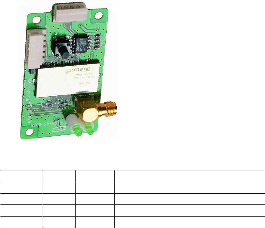
HPS-110
HandyPort-Serial
Wireless Solutions in your Hand
User’s Manual
Version 2.0
2
Table of Contents
1. INTRODUCTION....................................................................................................................3
1.1. FEATURES ........................................................................................................................ 3
1.2. PACKAGE .......................................................................................................................... 3
2. SPECIFICATIONS ................................................................................................................. 4
2.1. GENERAL.......................................................................................................................... 4
2.2. INTERFACE........................................................................................................................ 5
2.2.1. Notation ....................................................................................................................... 5
2.2.2. RS-232 Signals ........................................................................................................... 5
2.3. FACTORY SETTINGS .......................................................................................................... 6
2.4. STATUS LED..................................................................................................................... 6
2.5. RESET BUTTON................................................................................................................. 6
2.5.1. Entering the Configuration Mode ................................................................................ 6
2.5.2. Exiting the Configuration Mode................................................................................... 6
2.5.3. Re-connection ............................................................................................................. 6
3. USAGE................................................................................................................................... 7
3.1. HARDWARE INSTALLATION.................................................................................................. 7
3.2. HYPER TERMINAL SETTINGS .............................................................................................. 7
3.3. CONFIGURATION................................................................................................................ 7
3.3.1. Starting Configuration.................................................................................................. 7
3.3.2. Usage Printing............................................................................................................. 7
3.3.3. After Configuration ...................................................................................................... 7
3.4. COMMAND SET ................................................................................................................. 8

3
1. Introduction
Thank you for purchasing a HandyPort-Serial. The HandyPort-Serial can be used as a
component in many types of systems allowing them to communicate wirelessly with other
Bluetooth products such as PC-cards, laptops, handheld computers, mobile phones and other
HandyPort-Serial. The HandyPort-Serial is a suitable component in new products as well as in
existing products.
1.1. Features
z Supports Bluetooth Serial Port Profile and Generic Access Profile
z No need of external host and software
z Easy of installation and use
z Supports configuration of the local device
z Supports configuration of the remote device via Over-the-Air
z Easy of maintenance
z Supports up to 100 meter (Line of Sight)
1.2. Package
z HPS-110 2 EA
z Antenna 2 EA
z A soft copy of this manual1
1 This manual is required the software version 2.0 or above. If you have any questions, please
contact us.
HandyWave Co., Ltd.
202-4 yatap-dong, Bundang-gu, Seongnam City, Gyunggi Province 463-070, Republic of Korea
Tel: 82-31-709-8900, Fax: 82-31-708-9455
http://www.handywave.com/index3.htm

4
2. Specifications
2.1. General
Baud Rate z Up to 115.2kbps (Recommend above 2.4kbps)
z Supports 1.2/2.4/4.8/9.6/19.2/38.4/57.6/115.2kbps
Coverage Up to 100 M
Connection Point-to-Point
Signal TxD, RxD, GND
RS-232 Interface 2.5mm Wire to Board Connector Angle Type 4 Pin Male1
Standard Bluetooth Specification Version 1.1
Frequency 2.400 ~ 2.4835GHz
Hopping 1,600/Sec, 1MHz Channel Space
Modulation GFSK, 1Mbps, 0.5BT Gaussian
Tx. Power Max 20 / Typical 16dBm (Class 1)
Rx. Sensitivity -84dBm
Antenna Interface SMA Female
Antenna Gain Max. 2dBi
Power Supply +5VDC
Current
Consumption
Max. 110Ma
Operation
Temperature
-10 ~ 55 °C
Size 36.5mm (W) x 69mm (D) x 12mm (H)
1 Part number: 22-05-7045 (Old Part Number: 5268-04A) from Molex. Other side part number:
50-37-5043 (Old Part Number: 5264-04) from Molex.
5
2.2. Interface
2.2.1. Notation
z PWR: Power LED
z OPR: Link LED
z ANT: Antenna Connector (SMA Female)
z RST: Reset Button
z GND: Signal Ground
z RXD: RS-232 Received Data
z TXD: RS-232 Transmitted Data
z VCC: System Power
2.2.2. RS-232 Signals
Pin Number Notation Direction Description
1 VCC Input Vcc +5V
2 TxD Output RS-232 Transmitted Data
3 RxD Input RS-232 Received Data
4 GND N/A Signal Ground

6
2.3. Factory Settings
The following are the factory settings of COM port. You can change the factory settings of COM
port with commands. In this case, you have to remember the changed factory settings.
z Baud rate: 9600 bps
z Data Bit: 8 bit
z Parity Bit: No parity
z Stop Bit: 1 stop bit
z Flow control: None
2.4. Status LED
There are two LED on HPS-110.
z PWR (Green): It is an indication of power on/off status.
z LNK (Green): When a wireless link is on, it is turned on. If HPS-110 is in the
configuration mode, it will be flashing every second.
2.5. Reset Button
The RST button has the following functions.
z Enter / Exit the configuration mode
z Restore the factory settings1
z Disconnect and reconnect a wireless connection.
2.5.1. Entering the Configuration Mode
When the LNK LED is OFF, push the RST button. When the LNK LED is ON, you have to push
the RST button twice to enter the configuration mode. If you enter the configuration mode
successfully, LNK LED will be flashing every second. And HPS-110 COM port will be stored the
factory settings.
2.5.2. Exiting the Configuration Mode
You can have two options to exit the configuration mode.
z Exit the configuration mode by software: Type “X”.
z Exit the configuration mode by the RST button: Push the RST button.
2.5.3. Re-connection
When the LNK LED is on, you can push the RST button to disconnect and reconnect a wireless
link.
1 If you push the RST button, the COM port of HPS-110 will be stored the factory settings.

7
3. Usage
You can change the configuration of HPS-110 using Hyper Terminal1.
3.1. Hardware Installation
Step 1: Assemble a provided antenna to HPS-110 body.
Step 2: Plug a HPS-110 into the COM port of device.
Step 3: Power on.
Step 4: Configure the HPS-110, if necessary.
3.2. Hyper Terminal Settings
Baud Rate: 9600 bps / Data Bit: 8 / Parity Bit: None / Stop Bit: 1 / Flow Control: None /
Emulation: VT100
3.3. Configuration
3.3.1. Starting Configuration
Step 1: Plug a HPS-110 into a COM port of PC. And Power it on.
Step 2: Open a Hyper Terminal and set it up.
Step 3: Push the RST button on HPS-110. If you enter the configuration mode successfully, LNK
LED will be flashing every second.
Step 4: Hit the <Enter> key, 5 second later.
Step 5: Change the configuration of HPS-110 with commands, if necessary.
3.3.2. Usage Printing
If you are in the configuration mode, type “?<Enter>” for listing of commands. If you want to
know the usage of a command, type “?[command]<Enter>”. All commands and parameters are
case sensitive. And you cannot use a <Backspace>.
3.3.3. After Configuration
After finishing the configuration, you have to execute a command “X” to apply changes.
1 This manual is required the software version 2.0 or above.

8
3.4. Command Set
The commands are as follows1:
Item Syntax Description Remarks
1. Connecting
address
AAddr<CR> Set a remote device
address for a wireless
connection.
A local and remote
BD_ADDR always need to
be difference.
2. Baud rate BBR[D]<CR> Change the baud rate.
D (option): Change a
factory setting2.
Baud Rate (BR) - 0: 1200,
1: 2400, 2: 4800, 3: 9600,
4: 19200, 5: 38400, 6:
57600, 7: 115200
3. COM port CCOMPort<CR> Change a request serial port.
COMPort: ‘1’ ~ ‘7’
Only valid in connection mode 2.
4. PIN code EPIN<CR> Authentication Off: hit <Enter>
Authentication On: Type up to 11
characters
Paired adapters should
have a same PIN code.
5. Search timer GTO<CR> Set a search timeout.
TO (timeout): ASCII ‘0’ ~ “999”
Connection mode 3 only.
Default: 10 sec.
6. Max number
of search
HNO<CR> Set the max number of search.
NO: ASCII ‘0’ ~ “999”
Connection mode 3 only.
Default: 10
7. Search device ITO,NO[L]<CR> Execute searching devices.
TO: ASCII ‘0’ ~ “999”
NO: ASCII ‘0’ ~ “999”
L (option): Display a long form.
Connection mode 3 only.
‘,’: ASCII 0x2C
8. Discovery
mode
JE/D<CR> Set the discovery mode.
‘E’: Enable
‘D’: Disable
Connection mode 1 only.
Default: Enable
9. Low Power
Mode
KE/D<CR> Set the low power mode.
‘E’: Enable
‘D’: Disable
Default: Disable
1 If you push the RST button, the COM port of HPS-110 will be stored the factory settings.
2 If you change a factory setting for baud rate, you have to remember it.

9
10. Connection
mode
MMode<CR>1 Set a connection mode.
Mode: ‘0’ – ‘3’
Mode 0 & 2: Required a
remote address.
Mode 2: Required a serial
port.
0: 1:1 Mode
1: WAIT Mode
2: REGISTER and
CONNECT Mode
3: WAIT Command Mode
11. Friendly
name
NName<CR> Set a friendly name up to
11 characters.
12. Parity Bit PPA[D]2<CR> Set the parity bit.
D (option): Change a
factory setting3.
0: None, 1: Odd 2: Even
13. Connection
Timeout
QTO<CR> Set the connection timeout.
TO: ASCII ‘0’ ~ “999”
Connection mode 3 only.
Default: 10 sec.
14. Stop Bit SST[D]<CR> Set the stop bit.
D (option): Change a
factory setting4.
0: 1 Stop, 1: 2 Stop
15. Connect TAddr[,TO]<CR> Try to make a connection.
Addr: a remote address
TO (option): ASCII ‘0’ ~ “999”
Connection mode 3 only.
‘,’: ASCII 0x2C
Default Timeout: 10 sec.
16. Cancel U Cancel a command. Connection mode 3 only.
17. View V Display the device
information
You can find out a software
version.
18. CoD WCoD<CR> Set the class of device.
CoD: 6-Hex in ASCII
Default: “001F00”
19. Exit X Apply changes. Rebooting
20. Status Z Display the status of state
machine.
‘S’: Idle / ’P’: Pairing /
’C’: Connecting /
’A’: RF on / ’I’: Inquiring
21. Usage ?[C]<CR> Display the command list
or usage.
C: Command
AT+Z?<CR>: Command list
AT+Z?A<CR>: Usage of ‘A’
1 <CR>: Carriage Return (0x0D)
2 []: An optional parameter.
3 If you change a factory setting for parity bit, you have to remember it.
4 If you change a factory setting for stop bit, you have to remember it.
10
Note.
This device complies with Part 15 of the FCC Rules. Operation is subject to the following two
conditions: (1) This device may not cause harmful interference, and (2) this device must accept
any interference received, including interference that may cause undesired operation.
Note.
Modifications not expressly approved by this company could void the user’s authority to operate
the equipment.
Note.
This equipment has been tested and found no comply with the limits for a Class B digital device,
pursuant to part 15 of the FCC rules. These limits are designed to provide reasonable protection
against harmful interference in a residential installation. This equipment generates, uses and can
radiate radio frequency energy and, if not installed and used in accordance with the instructions,
may cause harmful interference to radio communications. However, there is no guarantee that
interference will not occur in a particular installation. If this equipment does cause harmful
interference to radio or television reception, which can be determined by turning the equipment
off and on, the user is encouraged to try to correct the interference by one or more of the
following measures;
- Reorient or relocate the receiving antenna.
- Increase the separation between the equipment and receiver.
- Connect the equipment into an outlet on a circuit different from that to which the
receiver is connected
- Consult the dealer or an experienced radio/TV technician for help.
INFORMATION TO USER
The users manual or instruction manual for an intentional or unintentional radiator shall caution
the user that changes or modifications not expressly approved by the party responsible for
compliance could void the user’s authority to operate the equipment.
CAUTION
FCC Radio-Frequency Exposure Statement
This equipment generates and radiates radio frequency energy. In order to comply with FCC
radio-frequency radiation exposure guidelines for an uncontrolled environment, this equipment
has to be installed and operated while maintaining a minimum body to antenna distance of 20cm.
User are not permitted to make changes or modify the system in any way.
The antenna(s) used for this transmitter must be installed to provide a separation distance of at
least 20cm from all persons and must not be collocated or operating in conjunction with any
other antenna or transmitter.