Hangzhou AiXiangJi Technology TYWE1S Tuya Smart Wi-Fi Module User Manual x
Hangzhou AiXiangJi Technology Co., Ltd. Tuya Smart Wi-Fi Module x
Contents
- 1. User manual
- 2. User Manual rev01
- 3. User Manual
User Manual rev01
TYWE1S DATASHEET
Tuya Smart Wi-Fi Module
1. Product Overview
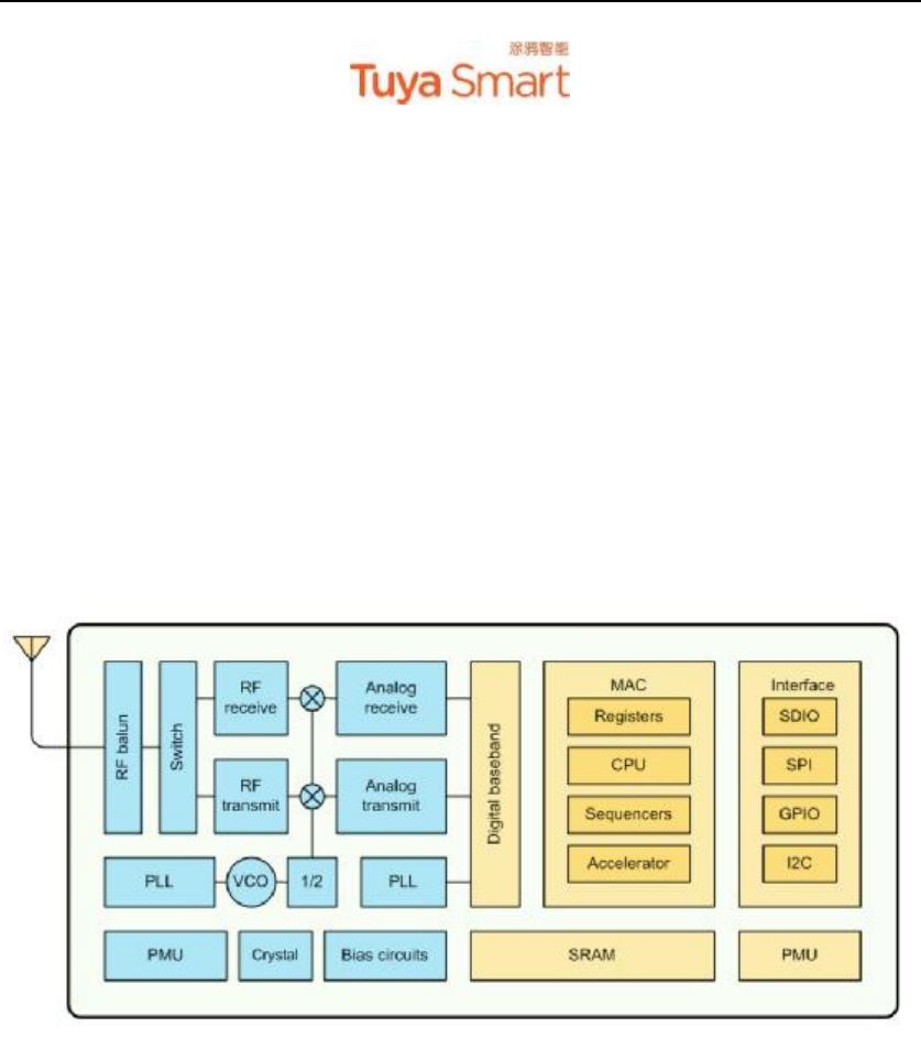
TYWE1S is a low power consumption module with built-in Wi-Fi connectivity solution
designed by HangZhou Tuya Technology Corporation. The Wi-Fi Module consist a highly
integrated wireless radio chip ESP8266EX and extra flash which has been programed with Wi-Fi
network protocol and plenty of software examples.TYWE1S also has an 32-bit CPU, 1M byte
flash, 36k SRAM and various peripheral resources.
TYWE1S is a RTOS platform, embedded with all the Wi-Fi MAC and TCP/IP protocol
function examples, users can customize their Wi-Fi product by using these software examples.
Figure 1 shows the block diagram of the TYWE1S.
Figure 1. The block diagram of the TYWE1S
1.1 Features
² Integrated low power consumption 32-bit CPU, also known as application processor
l Basic frequency can support both 80MHz and 160MHz
² Supply voltage range: 3V to 3.6V
² Peripherals: 6×GPIOs, 1×UART , 1×ADC
² Wi-Fi connectivity:
l 802.11 b/g/n
l Channel 1 to 11 @ 2.4GHz
l Support WPA/WPA2
l 19dBm output power in 802.11b mode
l Support STA/AP/STA+AP operation mode
l Support Smart Link function for both Android and iOS devices
l Standby power consumption is less than 0.1 mW (DTIM3)
l On-board PCB antenna, or IPEX connector for external antenna

TYWE1S DATASHEET
l CE, FCC certified
l Operating temperature range: 0℃ to 70℃ (Commercial grade), -40℃ to 85℃
(Industrial grade)
1.2 Main Application Fields
² Intelligent Building
² Intelligent home, Intelligent household applications
² Health care
² Industrial wireless control
² Baby monitor
² Webcam
² Intelligent bus
TYWE1S DATASHEET
2. Dimensions and Footprint
2.1 Dimensions
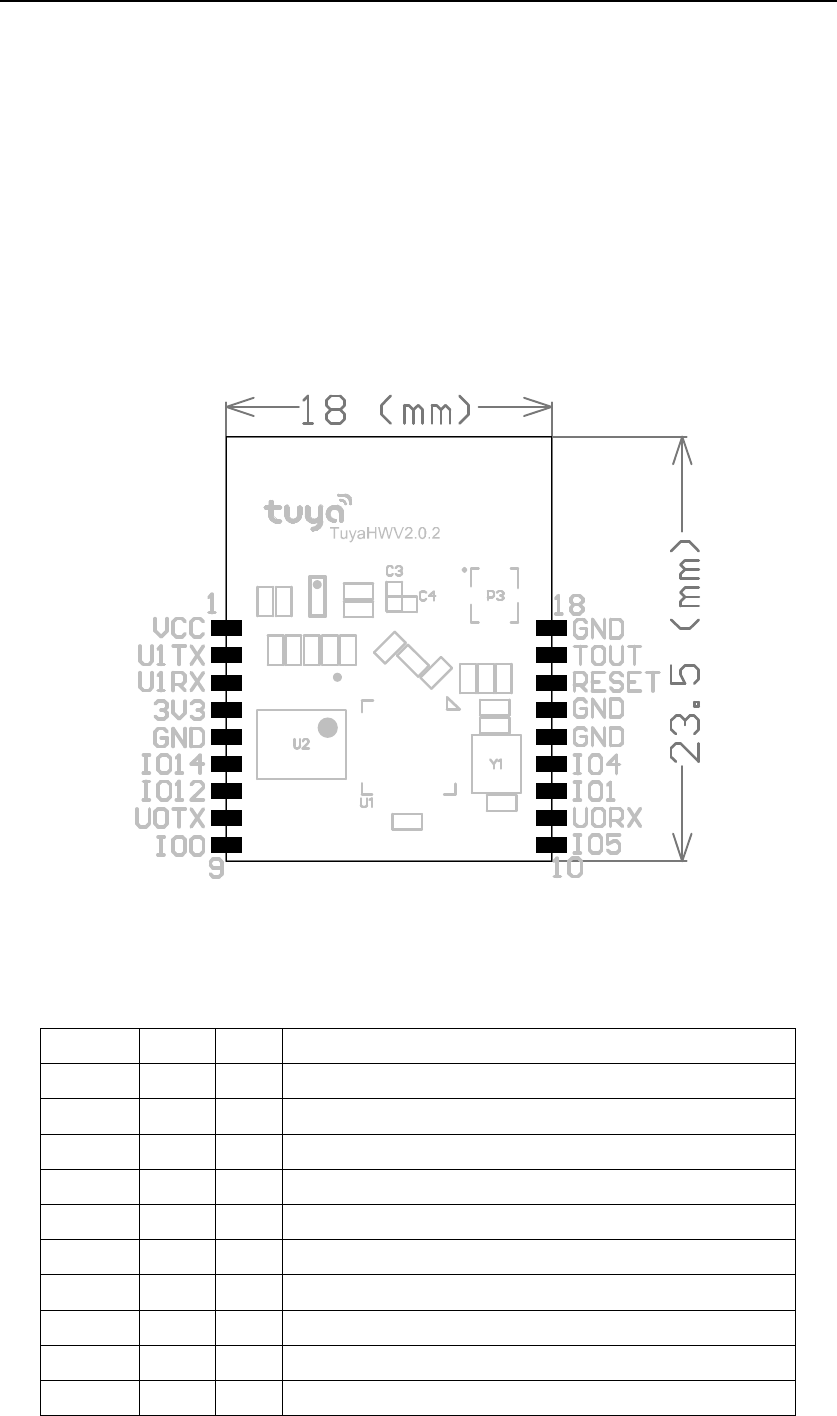
TYWE1S has 2 columns of Pins (2*9). The distance between each Pin is 1.5mm.
Size of TYWE1S: 18mm(W)*23.5mm(L)*4.1mm(H)
Figure 2 shows the dimensions of TYWE1S.
Figure 2. The dimensions of TYWE1S
2.2 Pin Definition
Table 1 shows the general pin attributes of TYWE1S
Table 1. The typical pin definition of TYWE1S
PIN NO.
NAME
TYPE
DESCRIPTION
1 VCC
S UART1 power (3.3V)
2 U1TX
I/O UART1_TXD
3 U1RX
I/O UART1_RXD
4 3V3 S Supply voltage (3.3V)
5 GND
S Ground
6 IO14
I/O GPIO_14
7 IO12
I/O GPIO_12
8 U0TX
I/O UART0_TXD(used to print module's internal information)
9 IO0 I/O GPIO_0(processing during initials, caution when used)
10 IO5 I/O GPIO_5

TYWE1S DATASHEET
11 U0RX
I/O UART0_RXD(used to print module's internal information)
12 IO1 I/O GPIO_1(status is uncertain during initials)
13 IO4 I/O GPIO_4
14 GND
S Ground
15 GND
S Ground
16 RESET
I/O External reset singal(negative level effects)
17 TOUT
AI ADC terminal
18 GND
S Ground
Note: S: Power supply pins; I/O: Digital input or output pins; AI: Analog input.
TYWE1S DATASHEET
3. Electrical Characteristics
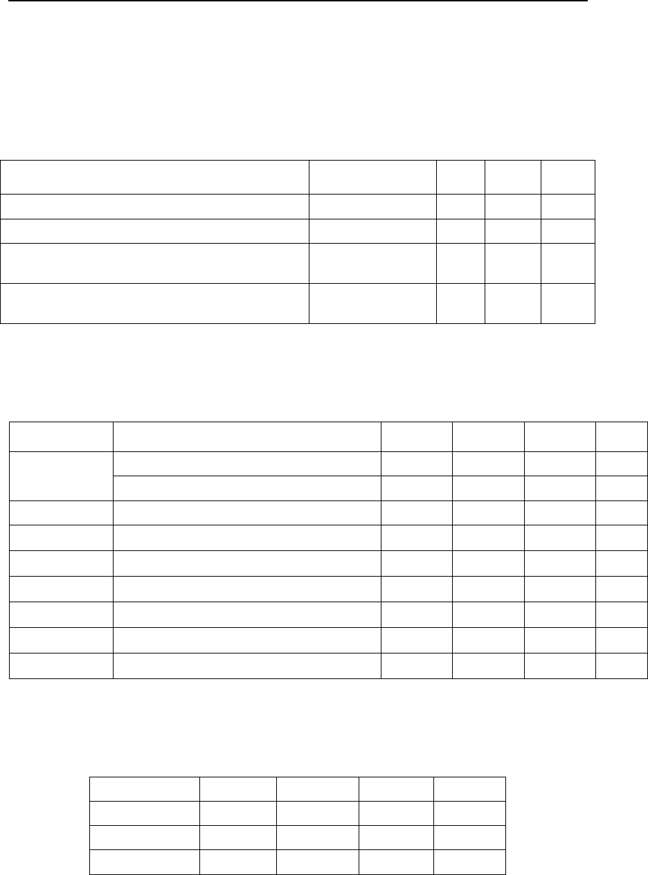
3.1 Absolute Maximum Ratings
Table 2. Absolute Maximum Ratings
PARAMETERS DESCRIPTION MIN
MAX
UNIT
Ts Storage temperature
-40 125 ℃
VDD Supply voltage - 3.6 V
Electrostatic release quantity (Human body model)
TAMB-25℃ - 2 KV
Electrostatic release quantity (Machine model) TAMB-25℃ - 0.5 KV
3.2 Electrical Conditions
Table 3. Electrical Conditions
PARAMETERS
DESCRIPTION MIN TYPICAL
MAX UNIT
Temperature for Commercial grade -30 - 70 ℃
Ta Temperature for Industrial grade -40 - 85 ℃
VDD Supply voltage 3.0 - 3.6 V
VIL IO negative level input -0.3 - 3V3*0.25
V
VIH IO positive level input 3V3*0.75
- 3.6 V
VOL IO negative level output - - 3V3*0.1
V
VIH IO positive level output 3V3*0.8
- - V
Imax IO drive current - - 12 mA
Cpad Capacitance of the input pin - 2 - pF
3.3 Wi-Fi Transmitting Current Consumption
Table 4. Wi-Fi TX current consumption
PARAMETERS
MODE RATE TYPICAL
UNIT
IRF 11b 11Mbps 170 mA
IRF 11g 54Mbps 140 mA
IRF 11n MCS7 140 mA
3.4 Wi-Fi Receiving Current Consumption
Table 5. Wi-Fi RX current consumption

TYWE1S DATASHEET
PARAMETERS
MODE RATE TYPICAL
UNIT
IRF 11b 11Mbps 50 mA
IRF 11g 54Mbps 56 mA
IRF 11n MCS7 56 mA
3.5 Working Mode Current Consumption
Table 6. MCU working current consumption
WORK MODE
CONDITION TYPICAL
UNIT
Modem-Sleep CPU is processing, Wi-Fi modem turns off 15 mA
Light-Sleep CPU stops processing, Wi-Fi modem turns off 0.9 mA
Deep-Sleep CPU stops processing, Wi-Fi modem turns off, Wi-Fi disconnects 10 μA
Power Off Power off 0.5 μA
TYWE1S DATASHEET
4. WLAN Radio Specification
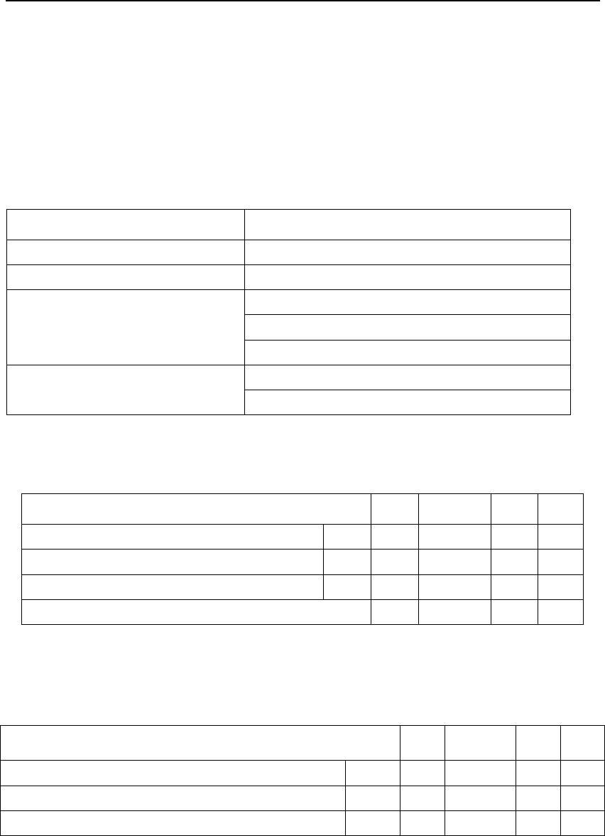
4.1 Basic Radio Frequency Characteristics
Table 7. Basic Radio frequency characteristics
PARAMETERS DESCRIPTION
Frequency band 2412MHz - 2462MHz
Wi-Fi standard IEEE 802.11n/g/b (Terminal 1-11)
11b:1,2,5.5,11(Mbps)
11g:6,9,12,18,24,36,48,54(Mbps)
Data transmitting rate
11n:HT20,MCS0~7
On-board PCB Antenna (Default)
Antenna type U.FL RF external antenna (optinal)
4.2 Wi-Fi Transmitting Power
Table 8. Wi-Fi transmitting power
PARAMETERS MIN
TYPICAL
MAX
UNIT
RF average output power, 802.11b CCK Mode 11M
- 17 - dBm
RF average output power, 802.11g OFDM Mode
54M
- 15 - dBm
RF average output power, 802.11n OFDM Mode
MCS7
- 13 - dBm
The Frequency error -10 - 10 ppm
4.3 Wi-Fi Receiving Sensitivity
Table 9. Wi-Fi Receiving sensitivity
PARAMETERS MIN
TYPICAL
MAX
UNIT
PER<8%, Receiving sensitivity, 802.11b CCK Mode 11M - -91 - dBm
PER<10%, Receiving sensitivity, 802.11g OFDM Mode
54M - -75 - dBm
PER<10%, Receiving sensitivity, 802.11n OFDM Mode
MCS7
- -72 - dBm

TYWE1S DATASHEET
Regulatory information for the OEMs and Integrators
The guidelines described within this document are provided to OEM integrators installing Tuya
Smart Wi-Fi Module in notebook and tablet PC host platforms. Adherence to these requirements
is necessary to meet the conditions of compliance with FCC rules, including RF exposure. When
all antenna type and placement guidelines described herein are fulfilled the Tuya Smart Wi-Fi
Module may be incorporated into notebook and tablet PC host platforms with no further
restrictions. If any of the guidelines described herein are not satisfied it may be necessary for the
OEM or integrator to perform additional testing and/or obtain additional approval. The OEM or
integrator is responsible to determine the required host regulatory testing and/or obtaining the
required host approvals for compliance
. Tuya Smart Wi-Fi Module are intended for OEMs and host integrators only.
. The Tuya Smart Wi-Fi Module must be operated with an access point that has been approved
for the country of operation.
. Changes or modification to Tuya Smart Wi-Fi Module by OEMs, integrators or other third parties
is not permitted. Any changes or modification to Tuya Smart Wi-Fi Module by OEMs, integrators
or other third parties will void authorization to operate
Information to Be Supplied to the End User by the OEM or Integrator
The following regulatory and safety notices must be published in documentation supplied to the
end user of the product or system incorporating the Tuya Smart Wi-Fi Module, in compliance
with local regulations. Host system must be labeled with "Contains FCC ID: 2AFNLTYWE1S ", FCC
ID displayed on label.
The Tuya Smart Wi-Fi Module must be installed and used in strict accordance with the
manufacturer's instructions as described in the user documentation that comes with the product.
Intel Corporation is not responsible for any radio or television interference caused by
unauthorized modification of the devices included with the wireless adapter kit or the
substitution or attachment of connecting cables and equipment other than that specified by Intel
Corporation. The correction of interference caused by such unauthorized modification,
substitution or attachment is the responsibility of the user. Intel Corporation and authorized
resellers or distributors are not liable for any damage or violation of government regulations that
may arise from the user failing to comply with these guidelines.
This device has been evaluated and shown compliant with the FCC RF Exposure limits under fixed
exposure conditions (antennas are greater than 20cm from a person’s body)when installed in
certain specific configurations.
The host system shall have a label showing: Contains FCC ID: 2AFNLTYWE1S
This product adopts the PCB antenna, the antenna gain is 1dBi
When the user selects U.FL RF connector antenna, it requires the a complete the antenna. the
kind of antenna that users can be use: 2.4 G RF antenna U.FL. RF connector(antenna type: FPC
antenna, Integral antenna)
(The gain of antenna : 1dBi)
TYWE1S DATASHEET
5. Antenna Information
5.1 Antenna Type
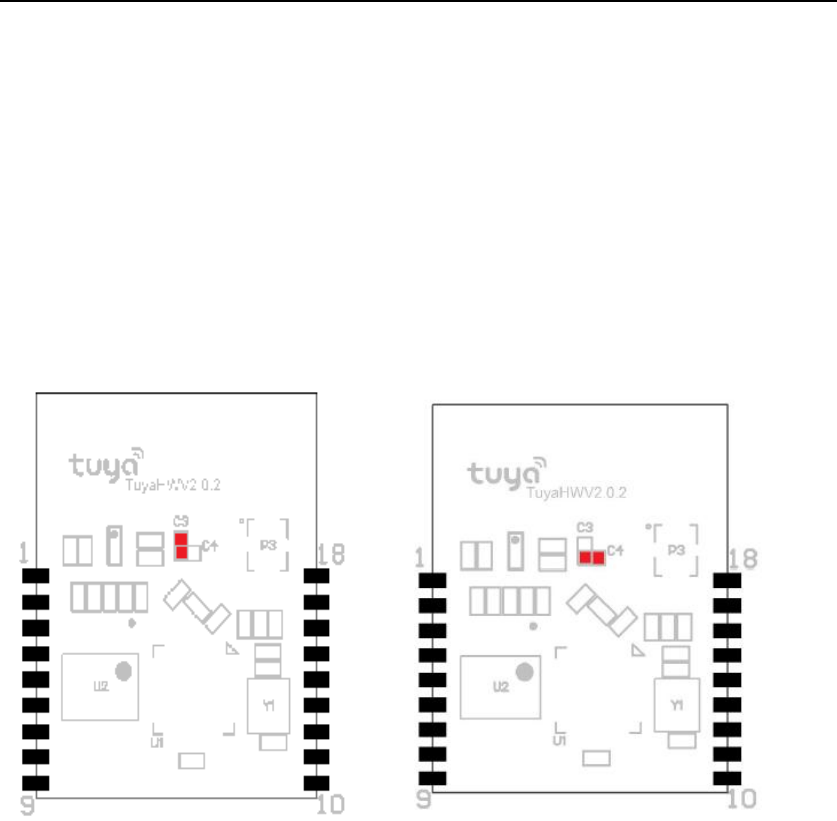
Antenna can be connected using On-board PCB antenna or an external antenna, the default
way is using the On-board PCB antenna.
User can modify the connection mode shown below: (TYWE1S has a resistance--0omh/0402
marked as red)
Figure 3. On-board PCB Antenna configuration Figure 4. External Antenna configuration
5.2 Reduce Antenna Interference
While using the On-board PCB antenna, in order to have the best Wi-Fi performance, it’s
recommended to keep a minimum 15mm distance between the antenna part and the other metal
pieces.
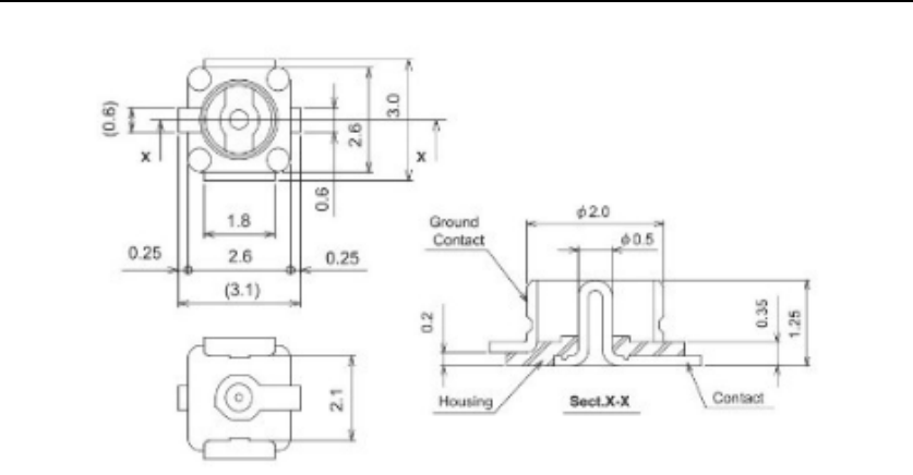
5.3 U.FL RF Connector
Figure 5 shows the physical parameter of the U.FL RF connector.
Figure 5. The physical parameter of the U.FL RF connector
TYWE1S DATASHEET
This device has been evaluated and shown compliant with the FCC RF Exposure limits under fixed
exposure conditions (antennas are greater than 20cm from a person’s body)when installed in
certain specific configurations.
The host system shall have a label showing: Contains FCC ID: 2AFNLTYWE1S
This product adopts the PCB antenna, the antenna gain is 1dBi, more details is in chapter 4.
When the user selects U.FL RF connector antenna, it requires the a complete the antenna. the
kind of antenna that users can be use: 2.4 G RF antenna U.FL. RF connector(antenna type: FPC
antenna, Integral antenna)
(The gain of antenna : 1dBi)
TYWE1S DATASHEET
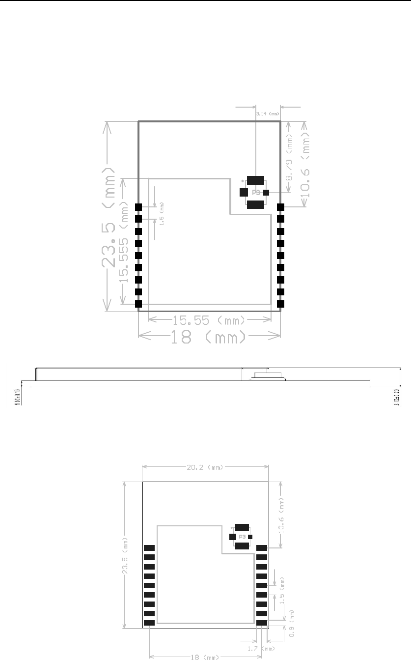
6. Packaging Information And Production Guide
6.1 Mechanical Dimensions
Figure 6. Top view of the module
Figure 7. Side view of the module
6.2 PCB Recommended Package
Figure 8. PCB Package Drawing

TYWE1S DATASHEET
6.3 Production Guide
² The storage for the delivered module should meet the following condition:
1. The anti-moisture bag should be kept in the environment with temperature < 30℃ and
humidity < 85% RH.
2. The expiration date is 6 months since the dry packaging products was sealed.
² Cautions:
1. All the operators should wear electrostatic ring in the whole process of production.
2. While operating, water and dirt should not have any contact with the modules.
FCC Caution: Any changes or modifications not expressly
approved by the party responsible for compliance could void the user's
authority to operate this equipment.
This device complies with Part 15 of the FCC Rules.
Operation is subject to the following two conditions: (1) This device may not
cause harmful interference, and (2) this device must accept any interference
received, including interference that may cause undesired operation.
This device and its antenna(s) must not be co-located or operating in conjunction
with any other antenna or transmitter.
15.105 Information to the user.
(b) For a Class B digital device or peripheral, the instructions furnished the
user shall include the following or similar statement, placed in a prominent
location in the text of the manual:
Note: This equipment has been tested and found to comply
with the limits for a Class B digital device, pursuant to part 15 of the FCC Rules.
These limits are designed to provide reasonable protection against harmful
interference in a residential installation. This equipment generates, uses and
can radiate radio frequency energy and, if not installed and used in
accordance with the instructions, may cause harmful interference to radio
communications. However, there is no guarantee that interference will not
occur in a particular installation. If this equipment does cause harmful
interference to radio or television reception, which can be determined by
turning the equipment off and on, the user is encouraged to try to correct the
interference by one or more of the following measures:
—Reorient or relocate the receiving antenna.
—Increase the separation between the equipment and receiver.
—Connect the equipment into an outlet on a circuit different from that to which
the receiver is connected.
—Consult the dealer or an experienced radio/TV technician for help.

TYWE1S DATASHEET
This equipment complies with FCC radiation exposure limits set forth for an uncontrolled environment.
This equipment should be installed and operated with minimum distance 20cm between the radiator
and your body.
Radiation Exposure Statement:
This equipment complies with FCC radiation exposure limits set forth for an
uncontrolled environment.
This transmitter must not be co-located or operating in conjunction with any other
antenna or transmitter.
The availability of some specific channels and/or operational frequency bands
are country dependent and are firmware programmed at the factory to match
the intended destination.
The firmware setting is not accessible by the end user.
The final end product must be labelled in a visible area with the following:
“Contains Transmitter Module 2AFNLTYWE1S”