Hangzhou Dunchong Technologies DCWA748 AP User Manual checklist
Hangzhou Dunchong Technologies Inc AP checklist
UserManual.wiki
>
Hangzhou Dunchong Technologies
>
DCWA748 User Manual
Users Manual
Navigation menu
Upload a User Manual
Namespaces
Wiki Guide
HTML
PDF
Info
Views
User Manual
Discussion / Help
Navigation
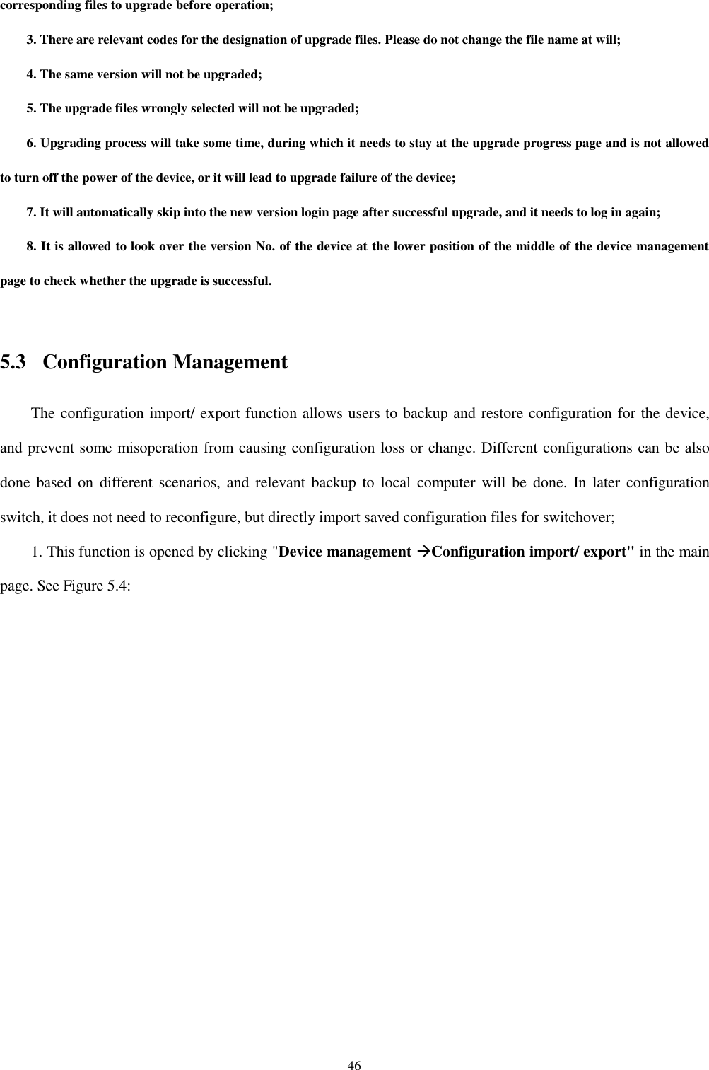
![2 Objects This manual mainly applies to the following engineers: • Network planners • Site technical support and maintenance personnel • Network administrators responsible for network configuration and maintenance Conventions of this manual 1. Convention on graphical interface format Format Designation < > Those with angle brackets "< >" refer to the name of buttons, such as "Click <OK>". [ ] Those with square brackets "[]" refers to window names, menu names and data sheets, such as "Pop up [New user] window". / Multilevel menu is separated by "/". For example, the multilevel menu of [File/ New/ File folder] refers to the menu item of [File folder] under the [New] submenu of the [File] menu. 2. This manual also adopts various striking marks to indicate places needed special attention during the operation, which bear the following meanings: Warn about matters required of attention during operation as improper operation can lead to data loss or device damage.](https://usermanual.wiki/Hangzhou-Dunchong-Technologies/DCWA748/User-Guide-3430355-Page-3.png)
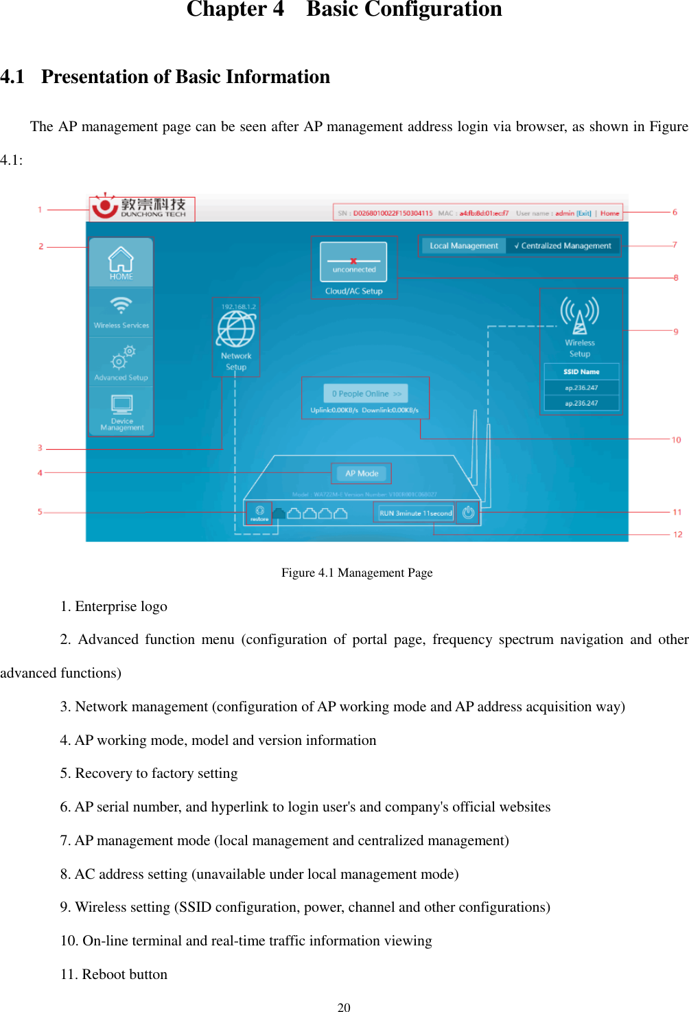
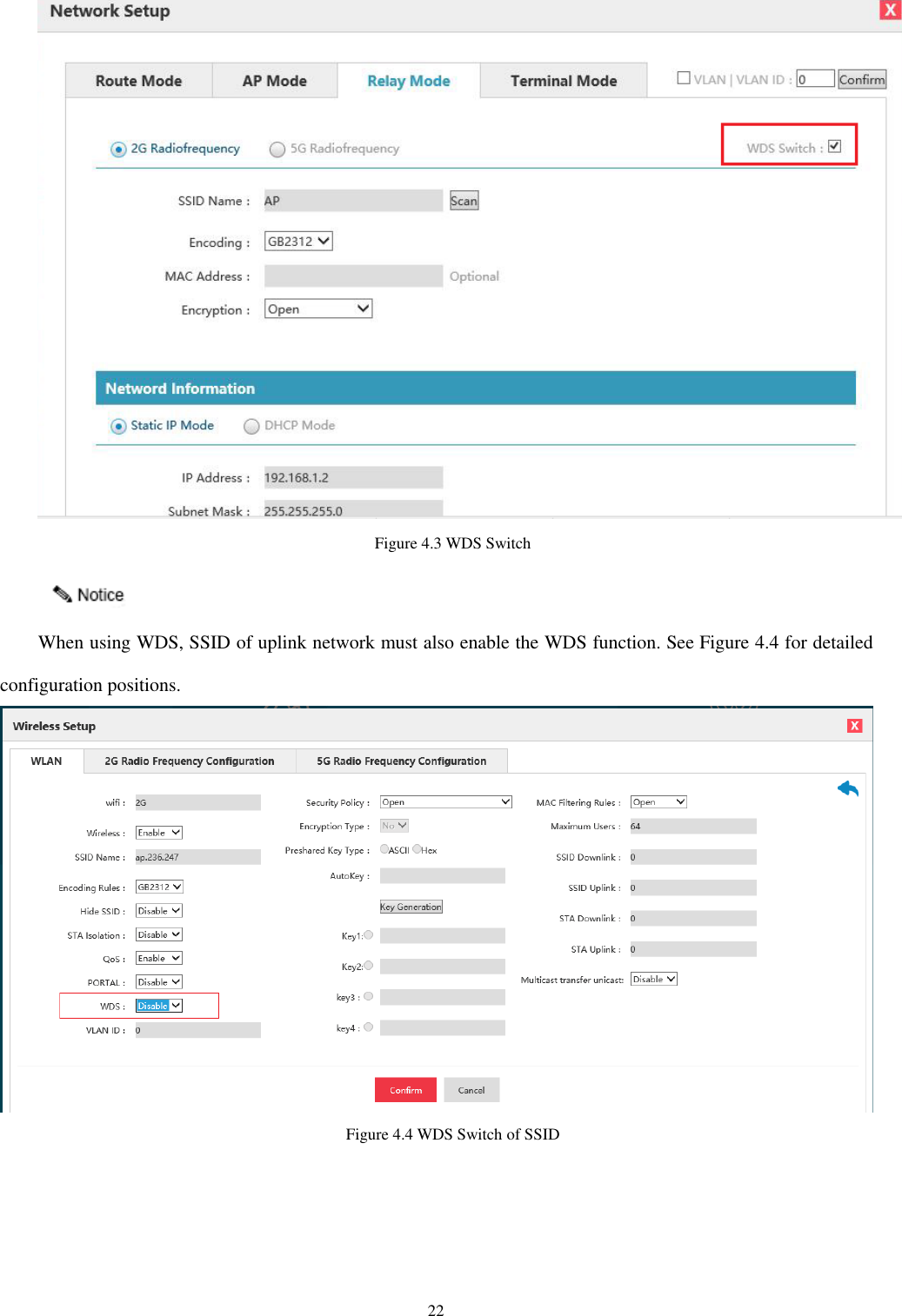
![21 12. AP operation duration 4.2 Network Setting Network configuration is mainly to set the working mode of device to meet the demands of different conditions. The working modes supported by the device currently include routing mode, AP mode, relay mode and terminal mode. Select "Network setting" in the home page to pop up the [Network setting] window. Figure 4.2 Four Modes of Network Configuration As shown in the figure above, the current mode is AP mode. If switching is required, select the desirable mode, click <OK>, and network mode switch will be completed after device reboot. There is a WDS switch on the top right corner of the relay mode and terminal mode pages. See details in Figure 4.3. When WDS opens, it shows that the WDS way is applied by the device; when WDS closes, it shows that the omnipotent relay way is applied by the device.](https://usermanual.wiki/Hangzhou-Dunchong-Technologies/DCWA748/User-Guide-3430355-Page-22.png)
![23 4.2.1 Routing mode Routing mode is a combination of simple type AP and broadband router and can realize wired Internet sharing in home wireless network, as well as wireless sharing access of ADSL and community broadband by means of router function. In addition, the routing mode can distribute all terminals with wireless and wired connection via the device into one subnet, by which, data interchange of various devices in the subnet is very convenient. The routing mode is, so to speak, an aggregation of AP, routing function and exchanger, and supports wire or wireless forming of the same subnet and directly connect with MODEM. This mode is generally applied to home and SOHO network, where the coverage area and users are generally not large, and only a wireless AP is enough. Routing mode can realize the access of ADSL network, and switch ADSL into wireless signals at the same time. Figure 4.5 Routing Mode Select "Network setting" in the home page to pop up the [Network setting] window.](https://usermanual.wiki/Hangzhou-Dunchong-Technologies/DCWA748/User-Guide-3430355-Page-24.png)
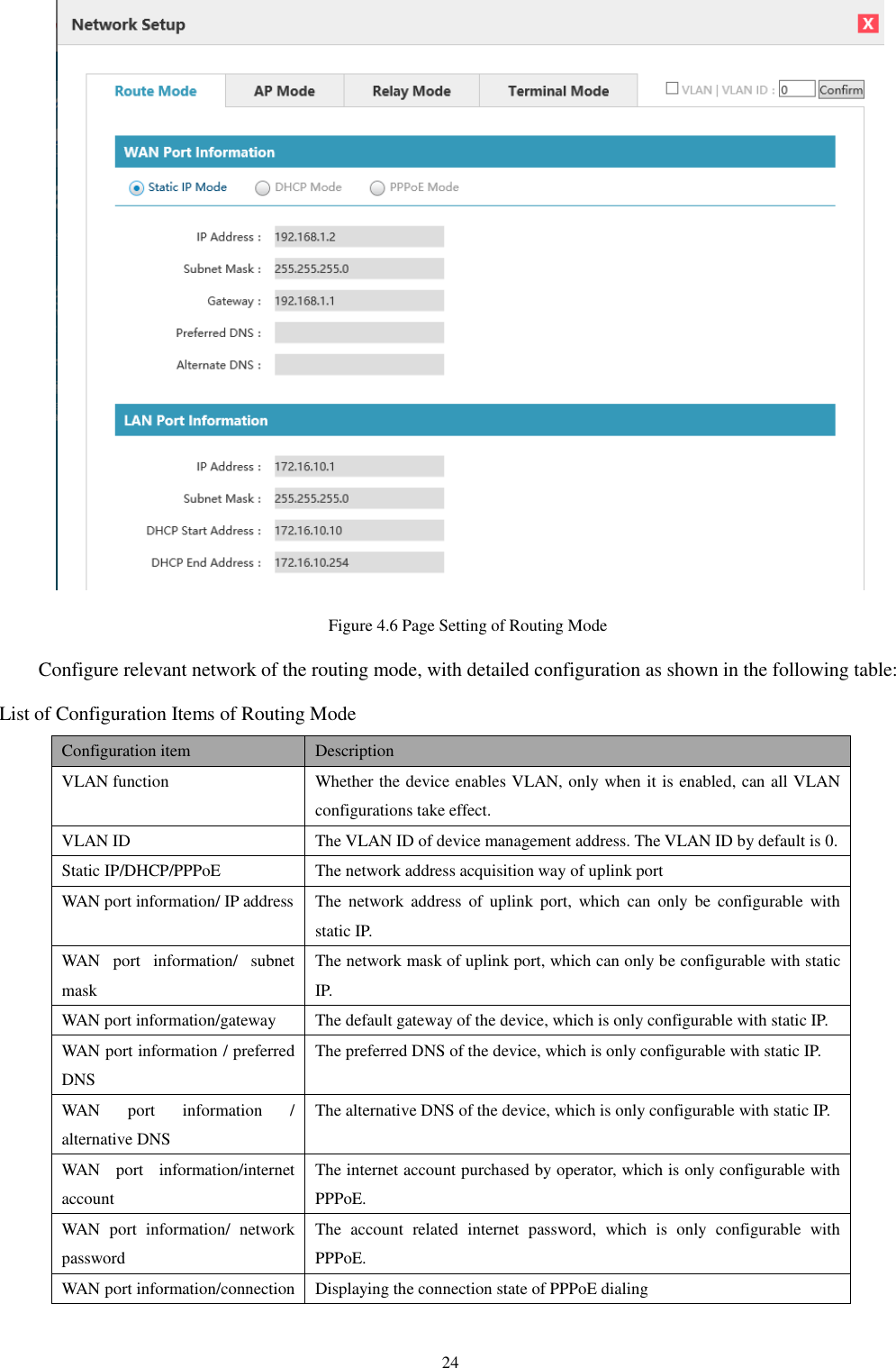
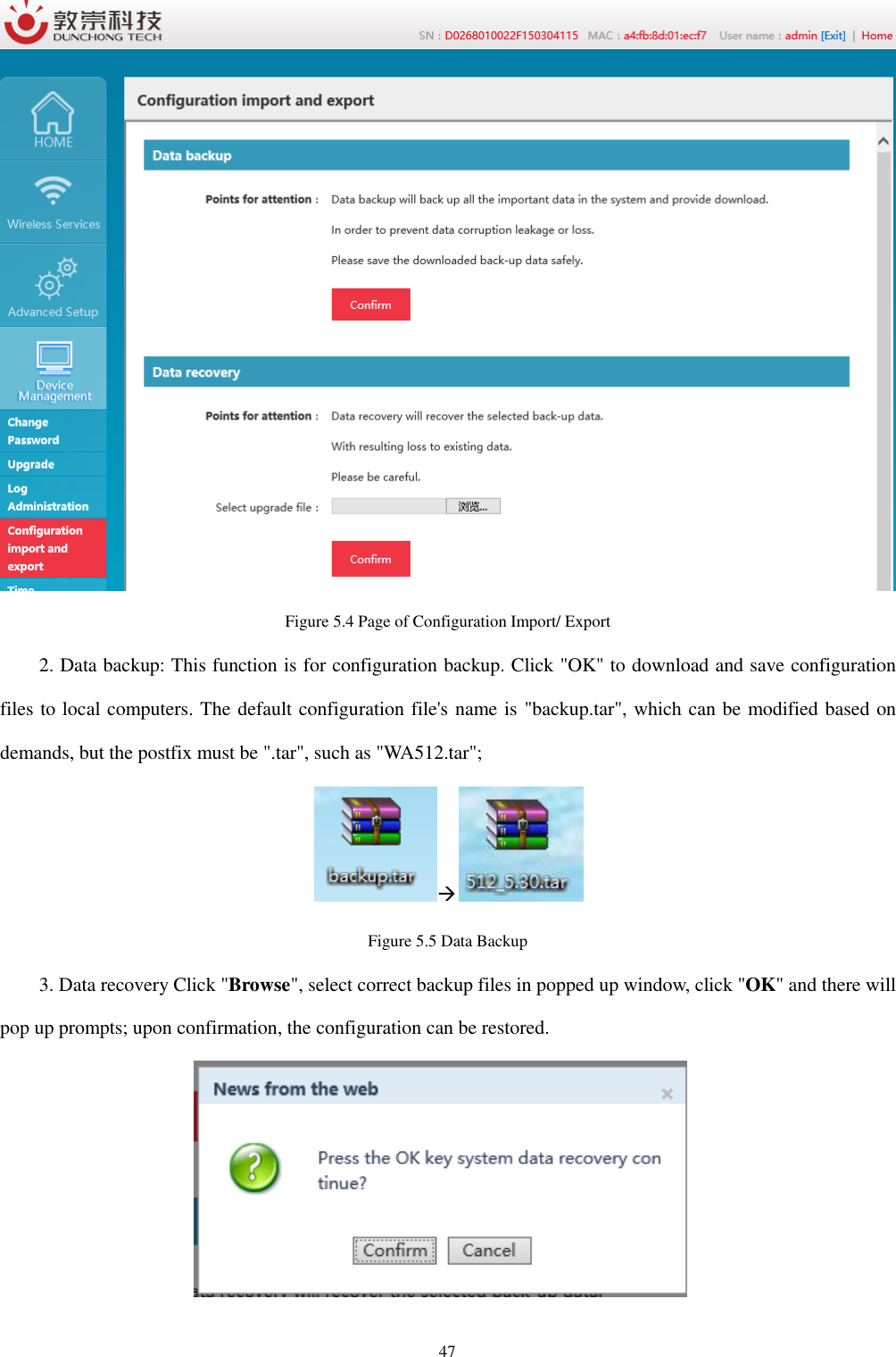
![25 state LAN port information/ IP address The IP address of LAN port, which as the gateway address of wireless terminal cannot be in the same network segment with WAN address. LAN port information/ subnet mask The subnet mask of LAN port, which is generally 255.255.255.0. LAN port information/ DHCP start address The start address of DHCP server LAN port information/ DHCP end address The end address of DHCP server 4.2.2 AP mode AP mode mainly provides wireless work station to visit wired LAN and visit wireless work station from wired LAN. Wireless work station within access point's coverage area can communicate with each other via it. Generally speaking, wireless AP is the communication bridge between wireless and wired network. The function of AP mode is to switch wired signal into wireless network after access it to wired network. Laptop or computer connects wireless WIFI LAN by receiving signal transmitted thereby. This point is a little similar to that of exchanger or wireless concentrator. AP mode is more applied to large companies, who need vast wireless access points to realize extensive network coverage. All access terminals belong to the same network at the same time, which facilitates the simple network control and management of such company's network administrator. Figure 4.7 AP Mode Select "Network setting" in the home page to pop up the [Network setting] window.](https://usermanual.wiki/Hangzhou-Dunchong-Technologies/DCWA748/User-Guide-3430355-Page-26.png)
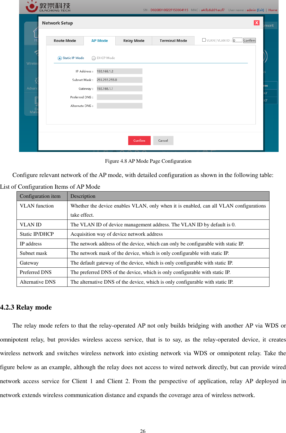
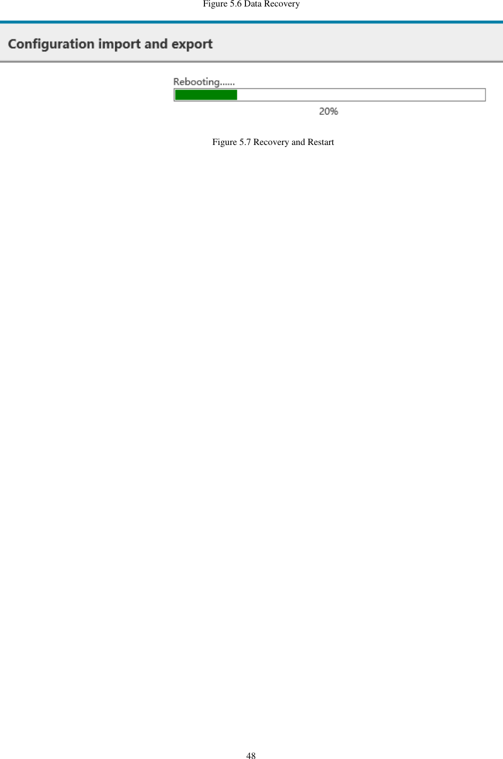
![27 Figure 4.9 Relay Mode Select "Network setting" in the home page to pop up the [Network setting] window. Figure 4.10 Relay Mode Page Configuration Configure relevant network of the relay mode, with detailed configuration as shown in the following table: List of Network Configuration of Relay Mode Configuration item Description VLAN function Whether the device enables VLAN, only when it is enabled, can all VLAN configurations take effect. VLAN ID The VLAN ID of device management address. The VLAN ID by default is 0. 2G RF/5G RF The working frequency band of uplink network Uplink network at the same moment can only operate in one frequency band. SSID name The SSID name of uplink network Coding way SSID coding way of uplink network, aims at Chinese SSID. MAC address The BSSID address of uplink network (it automatically connects SSID with the same name and strongest signal when filling gap) Encryption way The encryption way of uplink network (supporting OPEN, WPA-PSK and WPA2-PSK)](https://usermanual.wiki/Hangzhou-Dunchong-Technologies/DCWA748/User-Guide-3430355-Page-28.png)
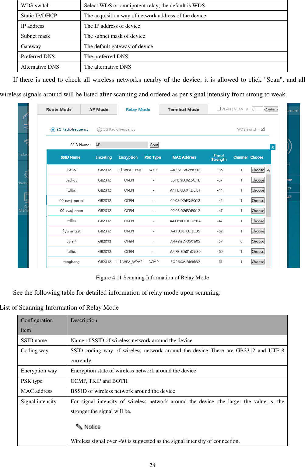
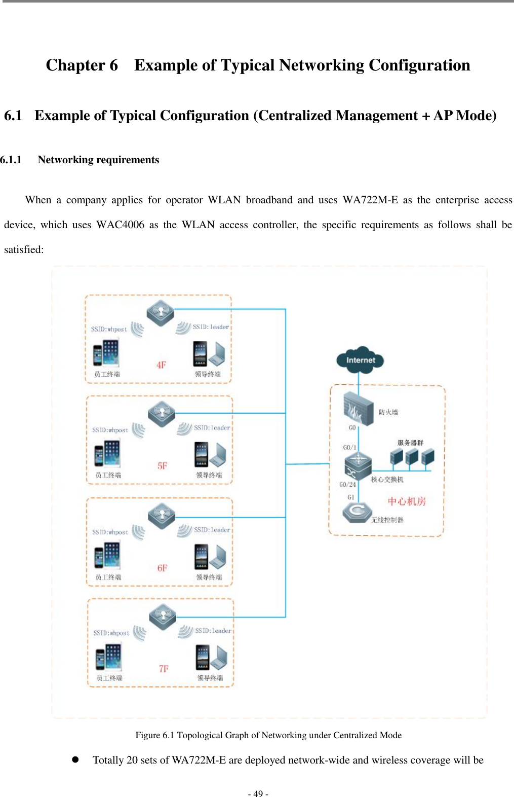
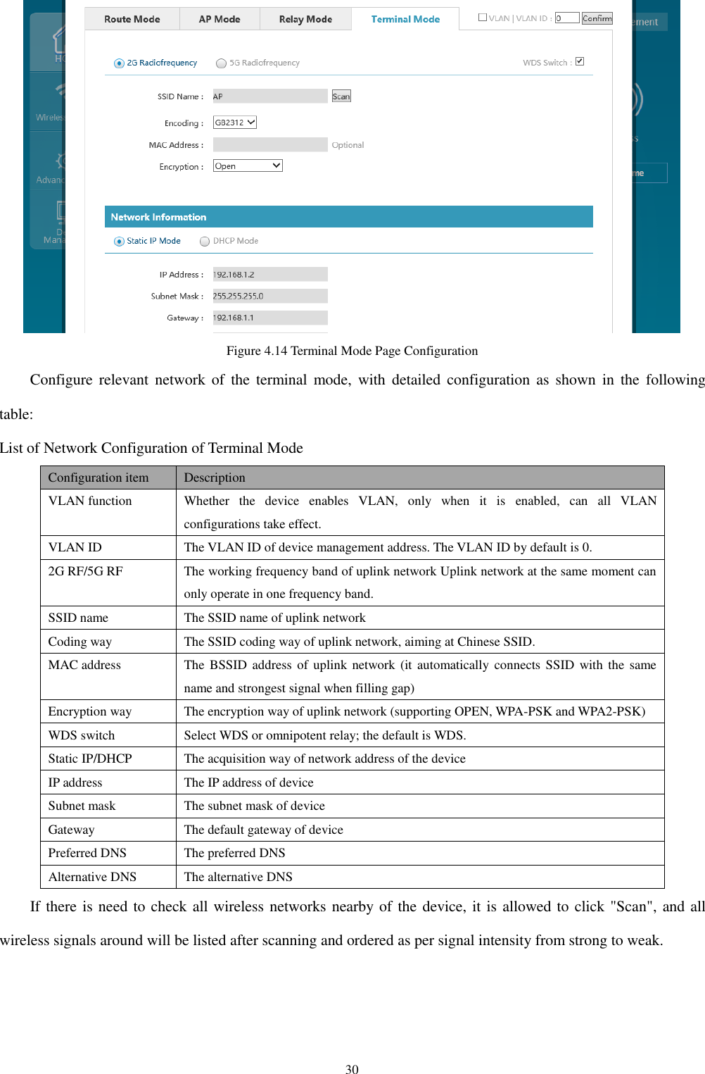
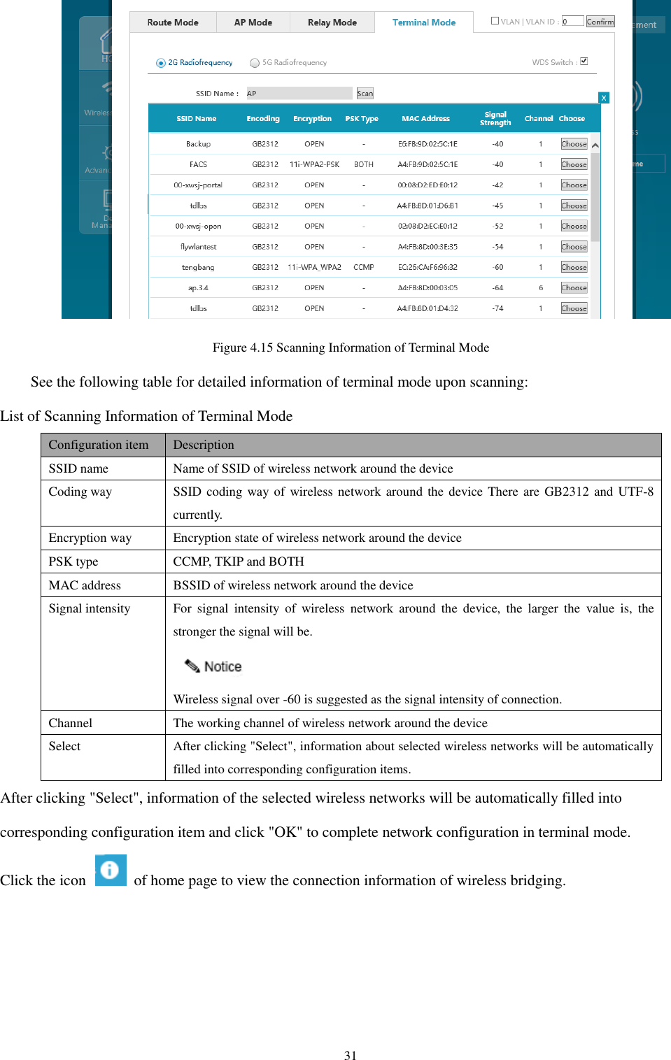
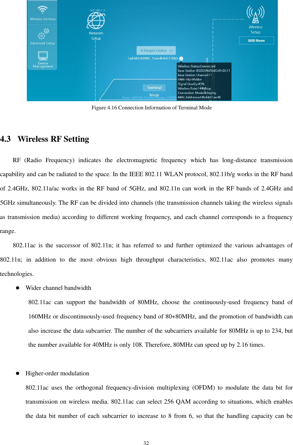
![29 Channel The working channel of wireless network around the device Selection After clicking "Select", information about selected wireless networks will be automatically filled into corresponding configuration items. After clicking "Select", information of the selected wireless networks will be automatically filled into corresponding configuration item and click "OK" to complete network configuration in relay mode. Click the icon of home page to view the connection information of wireless bridging. Figure 4.12 Scanning Information of Relay Mode 4.2.4 Terminal mode The terminal mode means the terminal-operated AP access to wireless network by means of wireless client via WDS or omnipotent relay, numerous hosts or printers in wired network can switch in wireless network via terminal mode AP, and it is equivalent to the working mode of CPE device. Figure 4.13 Terminal Mode Select "Network setting" in the home page to pop up the [Network setting] window.](https://usermanual.wiki/Hangzhou-Dunchong-Technologies/DCWA748/User-Guide-3430355-Page-30.png)
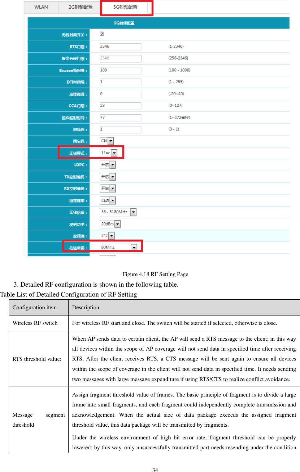
![33 increased by 33%. More empty by-pass flow and MU-MIMO 802.11ac can support 8 channels of spatial traffic at most, and the number of multiple spatial traffic supported is optional. However, it will be most efficient when the increasing of the spatial traffic number is combined with 802.11ac multiple-user multiple-input multiple-output (MU-MIMO) new functions. The 802.11ac technology can support 8 channels of spatial traffic at most under the MIMO mode, and each wireless terminal does not exceed 4 channels of spatial traffic under the multiple-user mode. Operative working frequency band (2.4G and 5.8G) of the device is corresponding to device models; some devices can only operate in 2.4G, some only in 5.8G, and some in 2.4G or 5.8G. 1. Select "Wireless setting" in the home page to pop up the [Wireless setting] window. Figure 4.17 Home Page of the Device 2. In the wireless setting window, select 2G RF or 5G RF configuration to enter the RF configuration page. If the selected configuration is under 11ac mode, enter 5G RF configuration, and select 11ac under wireless mode and 80MHz for channel bandwidth, as shown in the picture.](https://usermanual.wiki/Hangzhou-Dunchong-Technologies/DCWA748/User-Guide-3430355-Page-34.png)