Hangzhou Dunchong Technologies DCWA748 AP User Manual checklist
Hangzhou Dunchong Technologies Inc AP checklist
Users Manual

I
WA748 Wireless Access Point
User's Manual
Hangzhou Dunchong Technologies Inc.
Website: http://www.dunchongnet.com
Copyright © 2015 All copyrights reserved by Hangzhou Dunchong Technologies Inc. and its licensors. All rights reserved.
Any unit or individual shall not extract or reproduce partially or completely the contents of this manual without prior written
permission of the Company or spread it in any way.

1
Foreword
The User's Manual for WA Series Wireless Access Point will specifically guide you on how to locally
manage the device via Web setting page or command line. The foreword part includes the following
contents:
FCC ID:2ALQDDCWA748
FCC statement
This equipment has been tested and found to comply with the limits for a Class B digital device,
pursuant to Part 15 of the FCC Rules. These limits are designed to provide reasonable protection
against harmful interference in a residential installation. This equipment generates, uses and can
radiate radio frequency energy and, if not installed and used in accordance with the instructions, may
cause harmful interference to radio communications.
However, there is no guarantee that interference will not occur in a particular installation.
·
If this equipment does cause harmful interference to radio or television reception, which can be
determined by turning the equipment off and on, the user is encouraged to try to correct the
interference by one or more of the following measures:
—
Reorient or relocate the receiving antenna.
—
Increase the separation between the equipment and receiver.
—
Connect the equipment into an outlet on a circuit different from that to which the receiver is
connected.
—
Consult the dealer or an experienced radio/TV technician for help.
RF exposure warning
·
This equipment must be installed and operated in accordance with provided instructions and the
antenna(s) used for this transmitter must be installed to provide a separation distance of at least 20 cm
from all persons and must not be co-located or operating in conjunction with any other antenna or
transmitter.
NOTE: Any changes or modifications not expressly approved by the grantee of this device could void
the user's authority to operate the equipment.
This device complies with part 15 of the FCC Rules. Operation is subject to the following two conditions:
(1) This device may not cause harmful interference, and (2) this device must accept any interference
received, including interference that may cause undesired operation.

2
Objects
This manual mainly applies to the following engineers:
• Network planners
• Site technical support and maintenance personnel
• Network administrators responsible for network configuration and maintenance
Conventions of this manual
1. Convention on graphical interface format
Format
Designation
< >
Those with angle brackets "< >" refer to the name of buttons, such as "Click
<OK>".
[ ]
Those with square brackets "[]" refers to window names, menu names and data sheets,
such as "Pop up [New user] window".
/
Multilevel menu is separated by "/". For example, the multilevel menu of [File/ New/
File folder] refers to the menu item of [File folder] under the [New] submenu of the
[File] menu.
2. This manual also adopts various striking marks to indicate places needed special attention during
the operation, which bear the following meanings:
Warn about matters required of attention during operation as improper operation can
lead to data loss or device damage.
3
Table of Contents
Chapter 1 Product Introduction ................................................................................................................................... 6
1.1 Brief Introduction to Products ............................................................................................................................ 6
1.2 Product Features ................................................................................................................................................. 6
Chapter 2 Login Ways ................................................................................................................................................... 7
2.1 Device Management via WEB ........................................................................................................................... 7
2.2 Log in the Device via Serial Port ..................................................................................................................... 11
2.3 Device Management via Remote Login ........................................................................................................... 14
Chapter 3 Configuration of Working Mode .............................................................................................................. 17
3.1 Brief Introduction to Working Mode ................................................................................................................ 17
3.2 Local Management ........................................................................................................................................... 17
3.3 Centralized Management ................................................................................................................................. 17
3.4 Management Mode Switch .............................................................................................................................. 18
Chapter 4 Basic Configuration ................................................................................................................................... 20
4.1 Presentation of Basic Information .................................................................................................................... 20
4.2 Network Setting ............................................................................................................................................... 21
4.2.1 Routing mode .................................................................................................................................................. 23
4.2.2 AP mode .......................................................................................................................................................... 25
4.2.3 Relay mode ...................................................................................................................................................... 26
4.2.4 Terminal mode ................................................................................................................................................ 29
4.3 Wireless RF Setting .......................................................................................................................................... 32
4.4 WLAN Setting ................................................................................................................................................. 37
4.4.1 WLAN page configuration wizard .................................................................................................................. 38
4.5 On-line Terminal List ....................................................................................................................................... 41
4.6 AP Recovery to Factory Setting ....................................................................................................................... 43
4.7 AP Restart ........................................................................................................................................................ 43
Chapter 5 Device Management ................................................................................................................................... 44
5.1 Modify Password ............................................................................................................................................. 44
5.2 System Upgrade ............................................................................................................................................... 45
5.3 Configuration Management ............................................................................................................................. 46
Chapter 6 Example of Typical Networking Configuration ...................................................................................... 49
6.1 Example of Typical Configuration (Centralized Management + AP Mode) .................................................... 49
4
6.1.1 Networking requirements............................................................................................................................. 49
6.1.2 Precautions of configuration ........................................................................................................................ 50
6.1.3 Configuration steps ...................................................................................................................................... 50
Chapter 7 Fault Elimination ....................................................................................................................................... 53

3
Copyright notice
The user's manual of the Company contains no warranty, express or implied, including relevant warranty to
conduct sales or installation for special purposes.
The Company reserves the right to change or revise the manual without any further notice. Any content
herein is not allowed to be excerpted, copied or translated without written permission of the Company.
About this manual
The purpose of this manual is for the installation and application of access controller and wireless access
point. This manual includes the configuration procedure and methods to assist clients in solving unforeseen
problems.
To highlight some contents needed attention, the following special text and styles are used herein for
expression:
Refer to potential operation hazards that will cause hardware damage, loss of all data, device abnormalities,
etc.
Refer to important information and prompts for easy and better using the device.
Bold: Refer to important functions or setting steps needed special attention.
6
Chapter 1 Product Introduction
1.1 Brief Introduction to Products
WA series wireless product is a new generation of gigabit high-speed wireless access device (hereinafter
referred to as AP) based on 802.11n/802.11ac technology independently developed by Hangzhou Dunchong
Technologies Inc., can offer 600Mbps-1Gbps wireless access rate and cover larger areas. The uplink interface of
this wireless product adopts gigabit Ethernet interface for access, which breaks through the restriction of 100M
Ethernet interface, and makes the application of wireless multimedia possible. This product supports two Working
modes, i.e. local management and centralized management, which can be flexibly switched via command line
based on the demand of networking planning. For centralized management, it shall be used together with access
controller; while for local management, independent networking can be realized. The characters of these two
working modes (local management/ centralized management) are beneficial for smoothly upgrading the wireless
network of clients from small to large scale, accordingly excellently protecting the investment of users.
Product list:
1.2 Product Features
1. Realize high-performance wireless access 11AC
2. STBC (space-time block code) and LDPC (low density parity check)
3. Provide wired connection for gigabit Ethernet interface
4. Support local management and centralized management
5. Support frequency spectrum analysis
6. Abundant authentication ways
7. Offer only 11n access function
8. Support frequency spectrum navigation
9. Support Chinese SSID
10. Support load balancing
7
Chapter 2 Login Ways
2.1 Device Management via WEB
WEB management provides one friendly user operation interface, and browser can be used for device
reviewing and configuration. Steps of device configuration via WEB management interface are demonstrated
below by taking IE browser as an example.
1. Management address: As the device delivered is of centralized forwarding mode by default, under which
network the address of uplink port will be of dynamic acquisition way by default, so the device management
address is not settled, for which 169.254.10.10 can be used to manage the device;
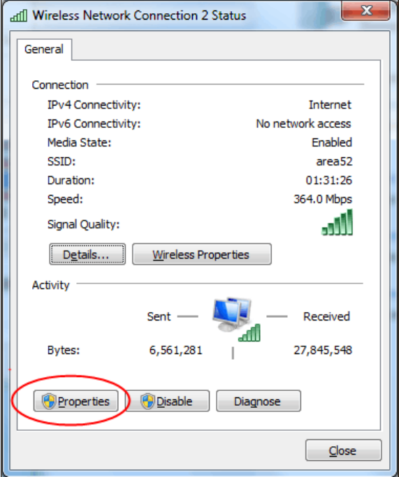
2. Configure static IP at local connection part to share the same network segment with the management
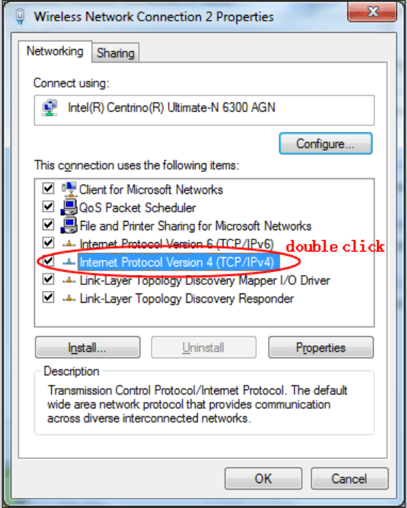
address; take win7 as an example, open local management, click "Attribute" (see Figure 2.1), then double click
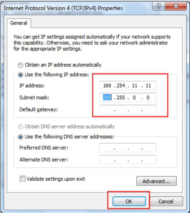
"Internet protocol version 4 (TCP/IPv4)" (see Figure 2.2), and click OK to exit upon configuration according to
Figure 2.3.
8
Figure 2.1 Attribute of PC Configuration
9
Figure 2.2 PC Configuration
10
Figure 2.3 IP Setting of PC
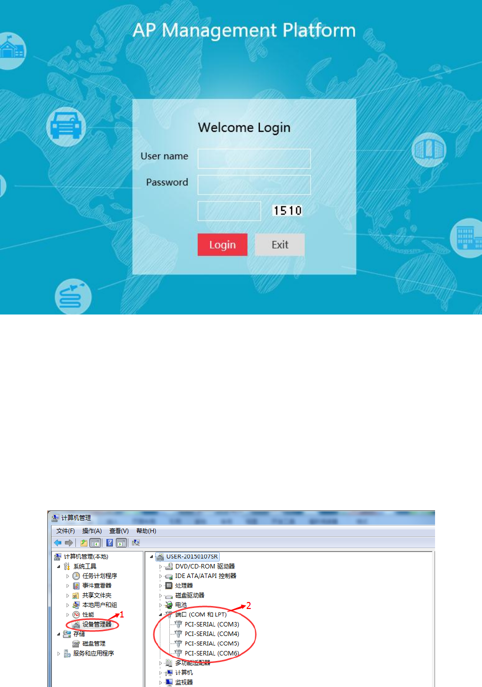
3. Open browser, enter AP management address, such as: 169.254.10.10, press Enter and there will appear a
login page, enter user name, password and verification code, and finally click login. User name by default is
admin, default password is password and modification can be done after login.
11
Figure 2.4 Login Page
2.2 Log in the Device via Serial Port
This way is mainly for constructors and managers to log in to facilitate information query and fault removal.
Steps of logging in device via serial port are demonstrated below by taking SecureCRT software as an example.
1. Ensure that the computer is connected with available serial port line, right click "Computer", click
"Manage", and then select "Device Manager" to view, as shown in Figure 2.5:
12
Figure 2.5 Device Manager
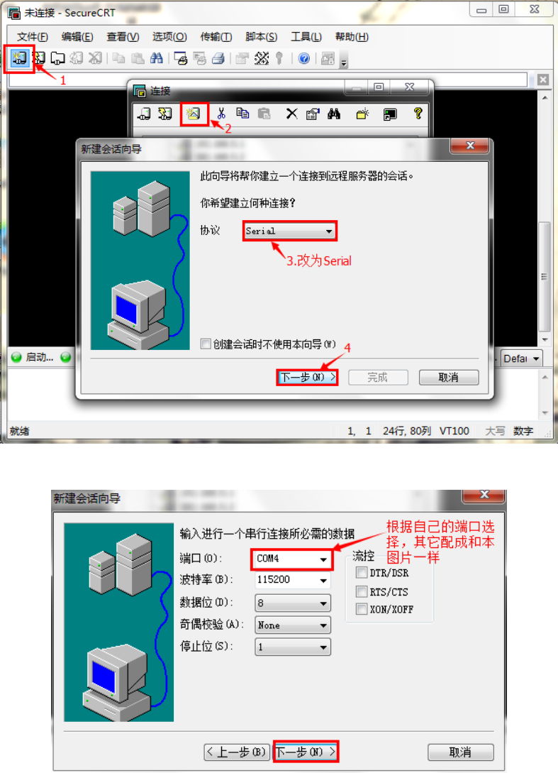
2. Open CRT software, create session and jump over this step if session is already crated.
Figure 2.6 CRT Wizard
Figure 2.7 CRT Serial Port Setting
13
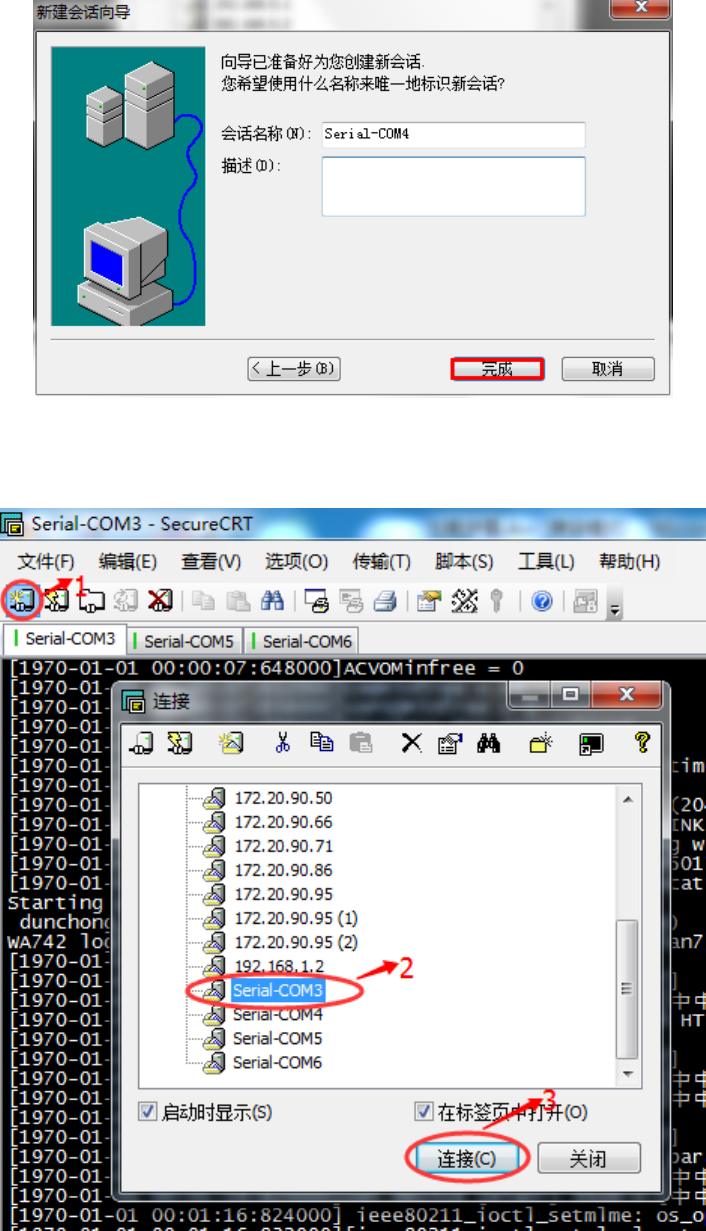
Figure 2.8 CRT Wizard Completed
3 Click "Connect" on the top left corner, select created session and connect, as shown in Figure 2.9.
Figure 2.9 CRT Connection
14
2.3 Device Management via Remote Login
The same as serial port login, this way is for constructors and managers to log in and can be used when serial
port cannot be connected. At present, it only supports SSH2 remote login. Steps of logging in device via serial
port are demonstrated below by taking SecureCRT software as an example.
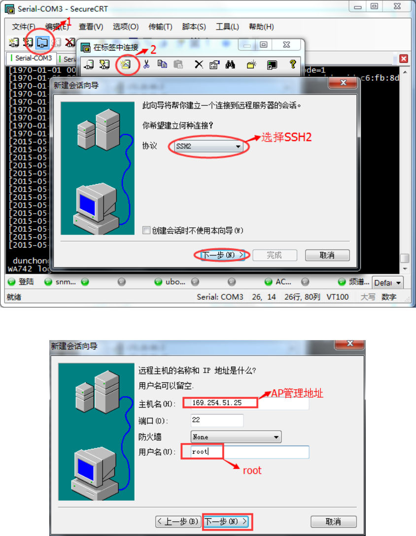
1. Calculate AP management address the same as that in WEP login and configure local IP, then open CRT
software to create session, and jump over this step if any session is already crated.
Figure 2.10 SSH2 Login
15
Figure 2.11 SSH2 Settings
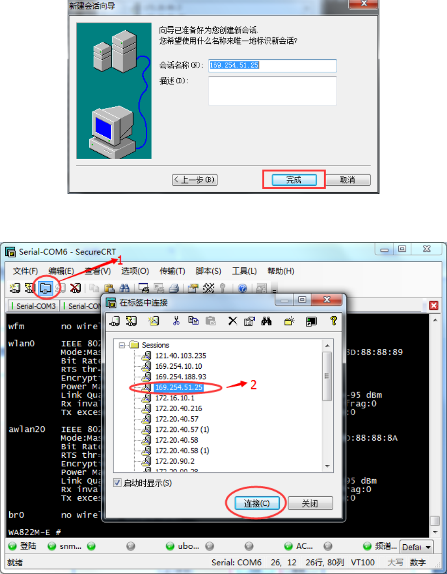
Figure 2.12 SSH2 Completed
2. Click "Connect" on the top left corner, select created session and connect, as shown in Figure 2.13.
Figure 2.13 SSH2 Connection Completed
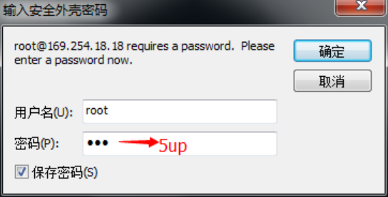
3. There will be prompt dialog box popped up in the first connection, click "Accept & Save" and there will
present the login interface; enter 5up in the password field and record the password; finally click OK to log in. It
will automatically log in later, as shown in Figure 2.14.
16
Figure 2.14 SSH2 Password
17
Chapter 3 Configuration of Working Mode
3.1 Brief Introduction to Working Mode
WLAN network can be created via two ways. One is local management mode; that is also the fat AP usually
mentioned. Centralized management cannot be realized under this mode and it can only conduct configuration and
management one by one, and is suitable for conditions with limited wireless coverage area and fewer number of
AP. The other is centralized management mode, i.e. the fit AP usually mentioned. This mode adopts the
architecture of AP+ access controller AC, and distributes configuration and version via AC, which facilitates
management and maintenance. It is suitable for the conditions with more number of AP and is in need of unified
maintenance.
3.2 Local Management
Local management AP is generally applied to SOHO home network or small WLAN, and can be deployed
for indoor coverage after wired network access. Indoor wireless terminals can visit INTERNET via local
management AP.
Local management has the following advantages and disadvantages:
Advantages: It can independently operate with no need of access controller and is suitable for small
networking with low cost.
Disadvantages: Configurations of local management are saved on AP, and the loss of AP device may cause
system configuration leak; Software upgrade needs to be conducted one by one, which increases maintenance
amount; The AP of each set only supports independent configuration, and the workload of AP configuration is too
large in constructing large-scale network; It can only realize layer two-layer roaming, but fails to provide security,
QOS and other advanced functions.
3.3 Centralized Management
In the architecture of centralized management, all wireless access functions are jointly completed by AP and
AC, and the communication between AP and AC is realized by CAPWAP protocol, and AC carries out
management work like configuration, upgrade and data collecting and optimizing for AP. This working mode has
18
the following advantages and disadvantages:
Advantages: With zero configuration, centralized management mode is easy to install and deploy and can be
centrally managed and distributed by AC. It supports fast switch, QoS, wireless network security protection,
network fault self-recovery and other advanced functions.
Disadvantages: With relatively high cost, it is not suitable for small-scale network; besides, AC configuration
is more complicated than local management.
3.4 Management Mode Switch
Two management ways can be switched free. There are two switching ways:
1. WEB switching
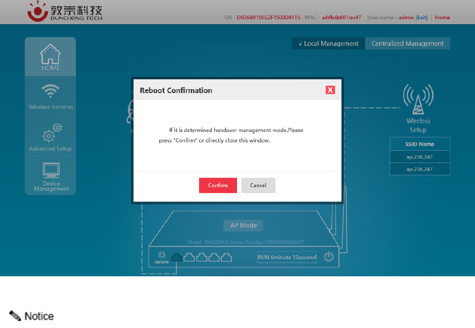
Log in AP page, and click local management or centralized management on the top right corner on home
page to complete switching of management modes.
Figure 3.1 WEB Switching of Management Way
Device reboot will occur after clicking OK, and then it will take effect.
2. Command switching
After device login via serial port or SSH2 or Telnet, enter show_ap AP_MODE to view the management
mode at present.
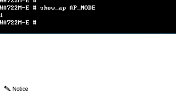
19
If 1 is displayed, it means centralized management. If 0 is displayed, it means local management.
Enter set_ap AP_MODE 1 to complete the setting of centralized management.
Enter set_ap AP_MODE 0 to complete the setting of local management.
After setting completed, enter reboot command to wait for its taking effect after device reboot.
20
Chapter 4 Basic Configuration
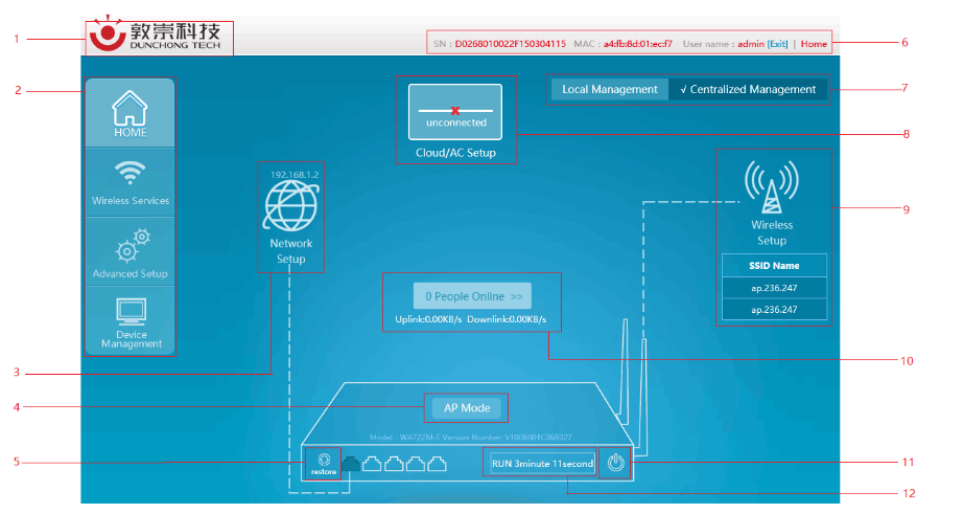
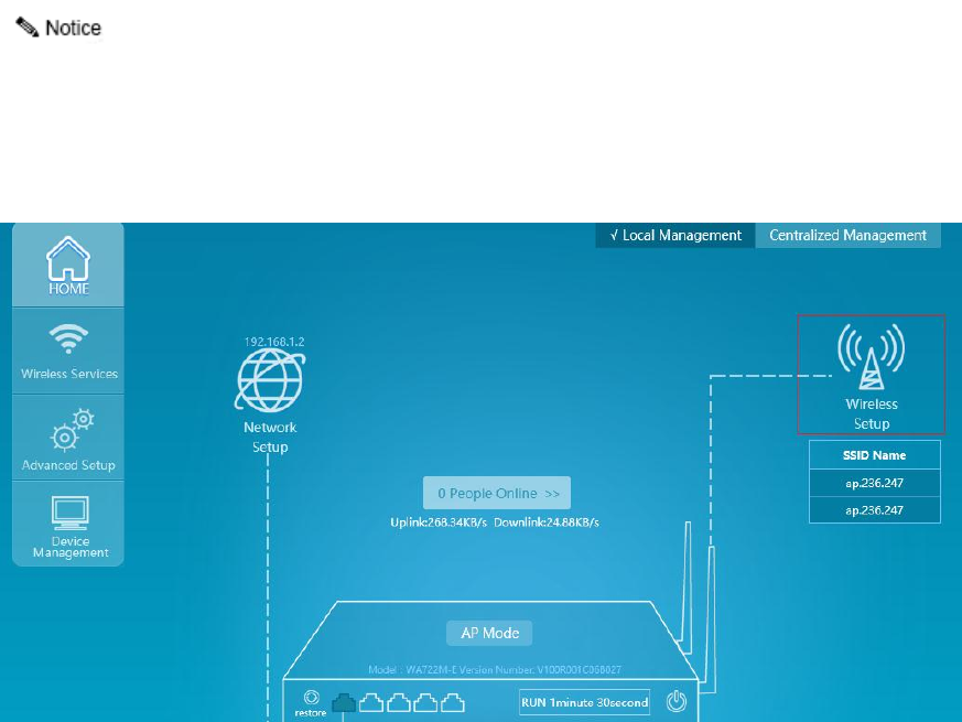
4.1 Presentation of Basic Information
The AP management page can be seen after AP management address login via browser, as shown in Figure
4.1:
Figure 4.1 Management Page
1. Enterprise logo
2. Advanced function menu (configuration of portal page, frequency spectrum navigation and other
advanced functions)
3. Network management (configuration of AP working mode and AP address acquisition way)
4. AP working mode, model and version information
5. Recovery to factory setting
6. AP serial number, and hyperlink to login user's and company's official websites
7. AP management mode (local management and centralized management)
8. AC address setting (unavailable under local management mode)
9. Wireless setting (SSID configuration, power, channel and other configurations)
10. On-line terminal and real-time traffic information viewing
11. Reboot button
21
12. AP operation duration
4.2 Network Setting
Network configuration is mainly to set the working mode of device to meet the demands of different
conditions. The working modes supported by the device currently include routing mode, AP mode, relay mode
and terminal mode.
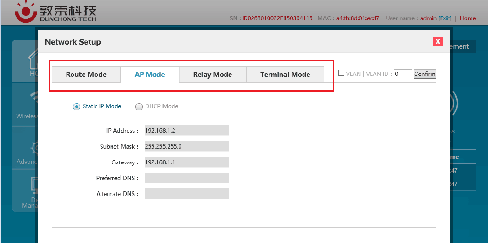
Select "Network setting" in the home page to pop up the [Network setting] window.
Figure 4.2 Four Modes of Network Configuration
As shown in the figure above, the current mode is AP mode. If switching is required, select the desirable
mode, click <OK>, and network mode switch will be completed after device reboot.
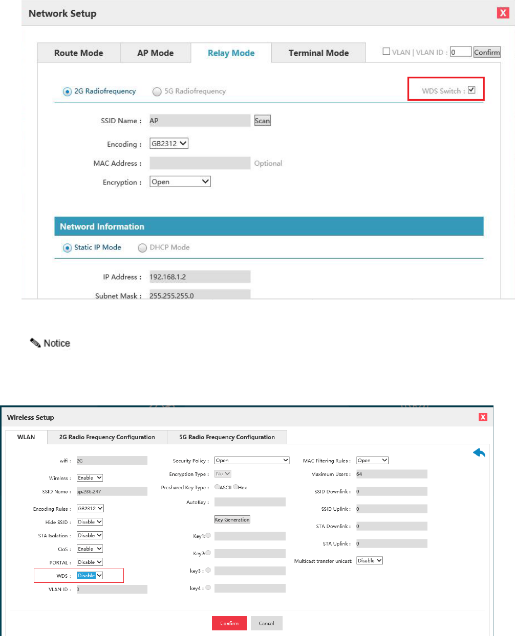
There is a WDS switch on the top right corner of the relay mode and terminal mode pages. See details in
Figure 4.3. When WDS opens, it shows that the WDS way is applied by the device; when WDS closes, it shows
that the omnipotent relay way is applied by the device.
22
Figure 4.3 WDS Switch
When using WDS, SSID of uplink network must also enable the WDS function. See Figure 4.4 for detailed
configuration positions.
Figure 4.4 WDS Switch of SSID

23
4.2.1 Routing mode
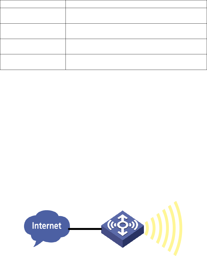
Routing mode is a combination of simple type AP and broadband router and can realize wired Internet
sharing in home wireless network, as well as wireless sharing access of ADSL and community broadband by
means of router function. In addition, the routing mode can distribute all terminals with wireless and wired
connection via the device into one subnet, by which, data interchange of various devices in the subnet is very
convenient. The routing mode is, so to speak, an aggregation of AP, routing function and exchanger, and supports
wire or wireless forming of the same subnet and directly connect with MODEM.
This mode is generally applied to home and SOHO network, where the coverage area and users are generally
not large, and only a wireless AP is enough. Routing mode can realize the access of ADSL network, and switch
ADSL into wireless signals at the same time.
Figure 4.5 Routing Mode
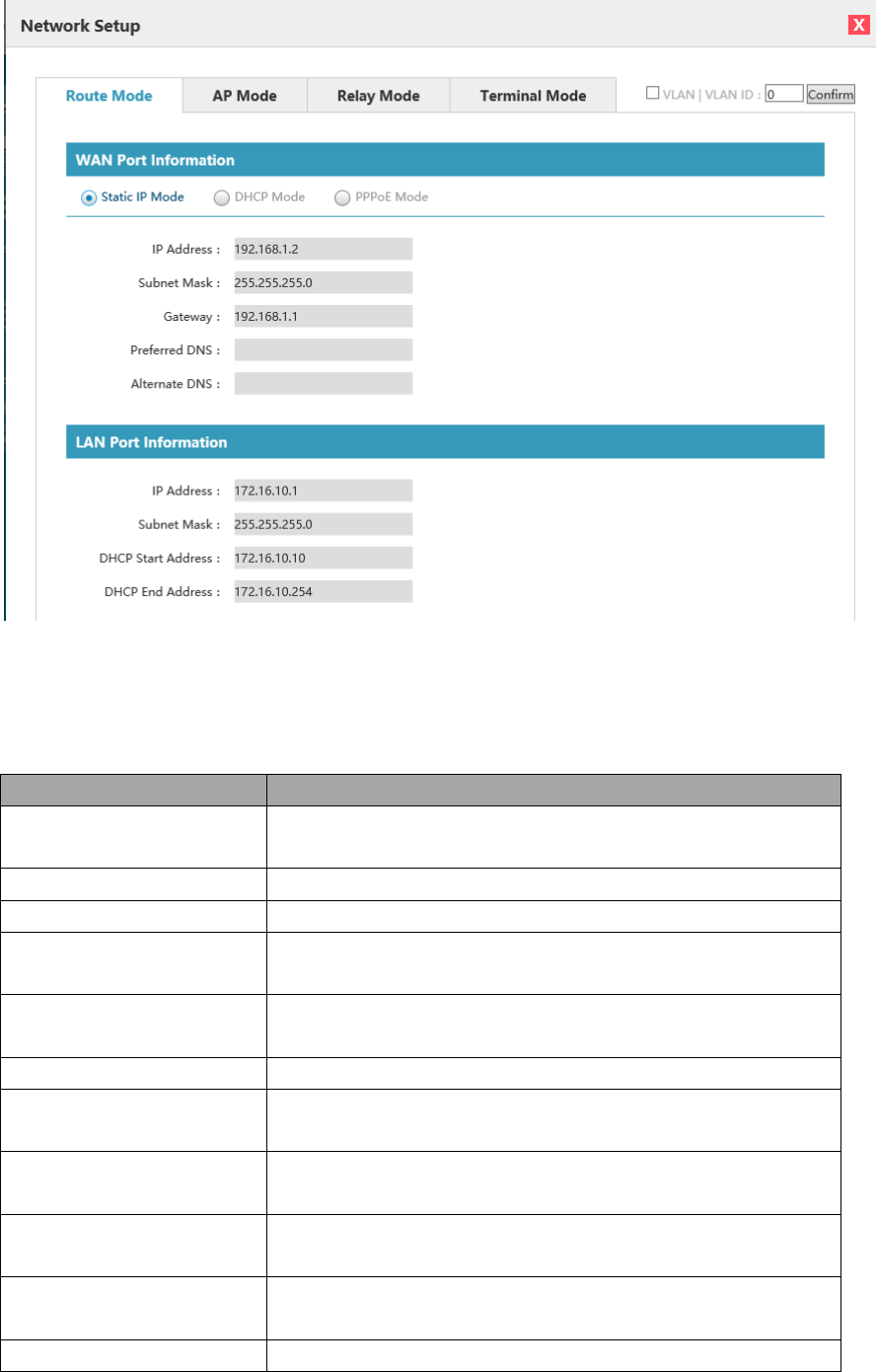
Select "Network setting" in the home page to pop up the [Network setting] window.
24
Figure 4.6 Page Setting of Routing Mode
Configure relevant network of the routing mode, with detailed configuration as shown in the following table:
List of Configuration Items of Routing Mode
Configuration item
Description
VLAN function
Whether the device enables VLAN, only when it is enabled, can all VLAN
configurations take effect.
VLAN ID
The VLAN ID of device management address. The VLAN ID by default is 0.
Static IP/DHCP/PPPoE
The network address acquisition way of uplink port
WAN port information/ IP address
The network address of uplink port, which can only be configurable with
static IP.
WAN port information/ subnet
mask
The network mask of uplink port, which can only be configurable with static
IP.
WAN port information/gateway
The default gateway of the device, which is only configurable with static IP.
WAN port information / preferred
DNS
The preferred DNS of the device, which is only configurable with static IP.
WAN port information /
alternative DNS
The alternative DNS of the device, which is only configurable with static IP.
WAN port information/internet
account
The internet account purchased by operator, which is only configurable with
PPPoE.
WAN port information/ network
password
The account related internet password, which is only configurable with
PPPoE.
WAN port information/connection
Displaying the connection state of PPPoE dialing
25
state
LAN port information/ IP address
The IP address of LAN port, which as the gateway address of wireless
terminal cannot be in the same network segment with WAN address.
LAN port information/ subnet
mask
The subnet mask of LAN port, which is generally 255.255.255.0.
LAN port information/ DHCP
start address
The start address of DHCP server
LAN port information/ DHCP end
address
The end address of DHCP server
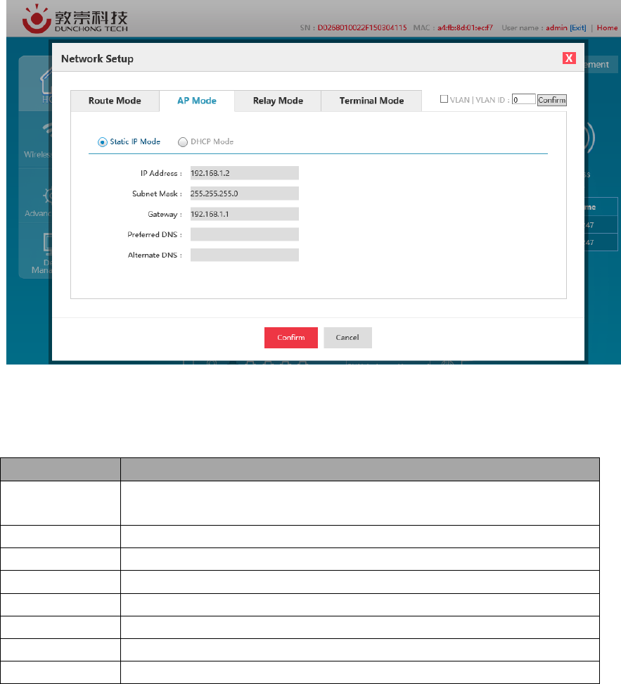
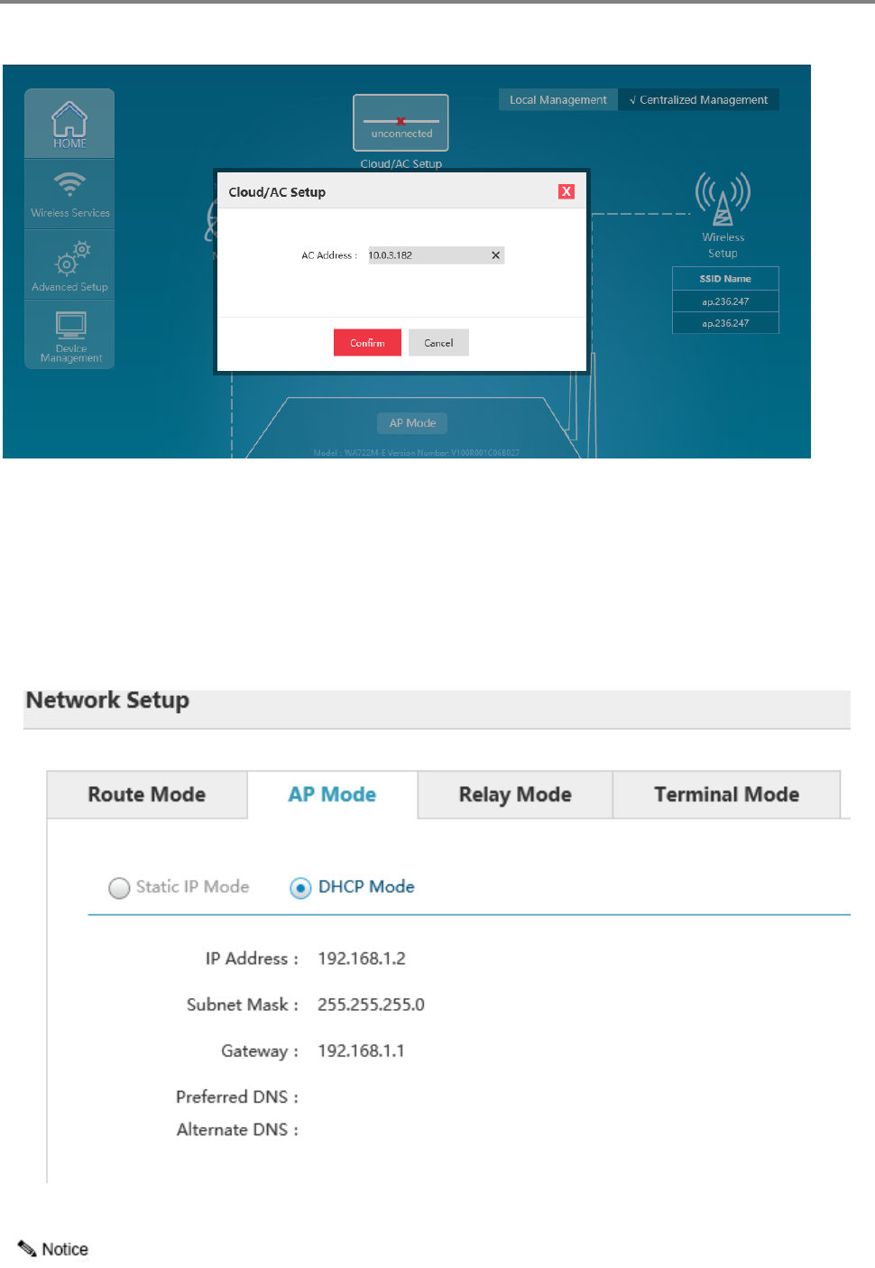
4.2.2 AP mode
AP mode mainly provides wireless work station to visit wired LAN and visit wireless work station from
wired LAN. Wireless work station within access point's coverage area can communicate with each other via it.
Generally speaking, wireless AP is the communication bridge between wireless and wired network. The function
of AP mode is to switch wired signal into wireless network after access it to wired network. Laptop or computer
connects wireless WIFI LAN by receiving signal transmitted thereby. This point is a little similar to that of
exchanger or wireless concentrator.
AP mode is more applied to large companies, who need vast wireless access points to realize extensive
network coverage. All access terminals belong to the same network at the same time, which facilitates the simple
network control and management of such company's network administrator.
Figure 4.7 AP Mode
Select "Network setting" in the home page to pop up the [Network setting] window.
26
Figure 4.8 AP Mode Page Configuration
Configure relevant network of the AP mode, with detailed configuration as shown in the following table:
List of Configuration Items of AP Mode
Configuration item
Description
VLAN function
Whether the device enables VLAN, only when it is enabled, can all VLAN configurations
take effect.
VLAN ID
The VLAN ID of device management address. The VLAN ID by default is 0.
Static IP/DHCP
Acquisition way of device network address
IP address
The network address of the device, which can only be configurable with static IP.
Subnet mask
The network mask of the device, which is only configurable with static IP.
Gateway
The default gateway of the device, which is only configurable with static IP.
Preferred DNS
The preferred DNS of the device, which is only configurable with static IP.
Alternative DNS
The alternative DNS of the device, which is only configurable with static IP.
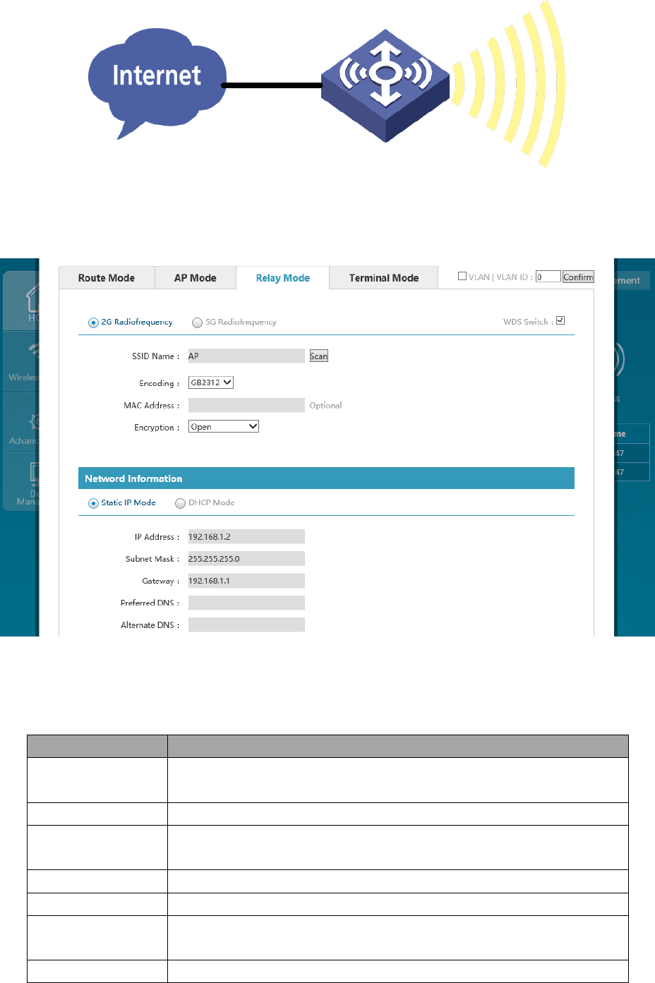
4.2.3 Relay mode
The relay mode refers to that the relay-operated AP not only builds bridging with another AP via WDS or
omnipotent relay, but provides wireless access service, that is to say, as the relay-operated device, it creates
wireless network and switches wireless network into existing network via WDS or omnipotent relay. Take the
figure below as an example, although the relay does not access to wired network directly, but can provide wired
network access service for Client 1 and Client 2. From the perspective of application, relay AP deployed in
network extends wireless communication distance and expands the coverage area of wireless network.
27
Figure 4.9 Relay Mode
Select "Network setting" in the home page to pop up the [Network setting] window.
Figure 4.10 Relay Mode Page Configuration
Configure relevant network of the relay mode, with detailed configuration as shown in the following table:
List of Network Configuration of Relay Mode
Configuration item
Description
VLAN function
Whether the device enables VLAN, only when it is enabled, can all VLAN
configurations take effect.
VLAN ID
The VLAN ID of device management address. The VLAN ID by default is 0.
2G RF/5G RF
The working frequency band of uplink network Uplink network at the same moment
can only operate in one frequency band.
SSID name
The SSID name of uplink network
Coding way
SSID coding way of uplink network, aims at Chinese SSID.
MAC address
The BSSID address of uplink network (it automatically connects SSID with the same
name and strongest signal when filling gap)
Encryption way
The encryption way of uplink network (supporting OPEN, WPA-PSK and WPA2-PSK)
28
WDS switch
Select WDS or omnipotent relay; the default is WDS.
Static IP/DHCP
The acquisition way of network address of the device
IP address
The IP address of device
Subnet mask
The subnet mask of device
Gateway
The default gateway of device
Preferred DNS
The preferred DNS
Alternative DNS
The alternative DNS
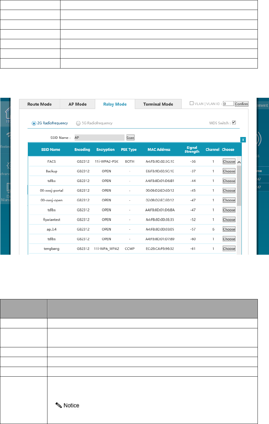
If there is need to check all wireless networks nearby of the device, it is allowed to click "Scan", and all
wireless signals around will be listed after scanning and ordered as per signal intensity from strong to weak.
Figure 4.11 Scanning Information of Relay Mode
See the following table for detailed information of relay mode upon scanning:
List of Scanning Information of Relay Mode
Configuration
item
Description
SSID name
Name of SSID of wireless network around the device
Coding way
SSID coding way of wireless network around the device There are GB2312 and UTF-8
currently.
Encryption way
Encryption state of wireless network around the device
PSK type
CCMP, TKIP and BOTH
MAC address
BSSID of wireless network around the device
Signal intensity
For signal intensity of wireless network around the device, the larger the value is, the
stronger the signal will be.
Wireless signal over -60 is suggested as the signal intensity of connection.
29
Channel
The working channel of wireless network around the device
Selection
After clicking "Select", information about selected wireless networks will be automatically
filled into corresponding configuration items.
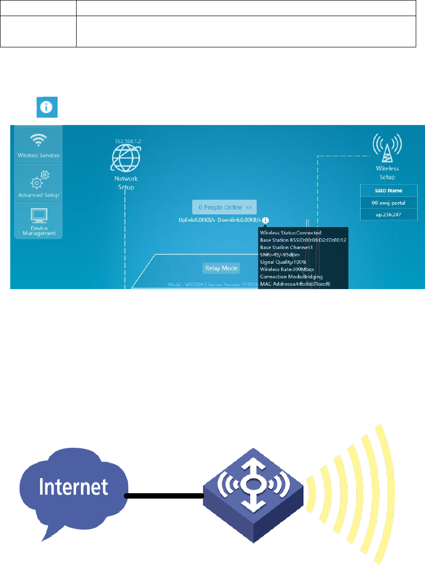
After clicking "Select", information of the selected wireless networks will be automatically filled into
corresponding configuration item and click "OK" to complete network configuration in relay mode.
Click the icon of home page to view the connection information of wireless bridging.
Figure 4.12 Scanning Information of Relay Mode
4.2.4 Terminal mode
The terminal mode means the terminal-operated AP access to wireless network by means of wireless client
via WDS or omnipotent relay, numerous hosts or printers in wired network can switch in wireless network via
terminal mode AP, and it is equivalent to the working mode of CPE device.
Figure 4.13 Terminal Mode
Select "Network setting" in the home page to pop up the [Network setting] window.
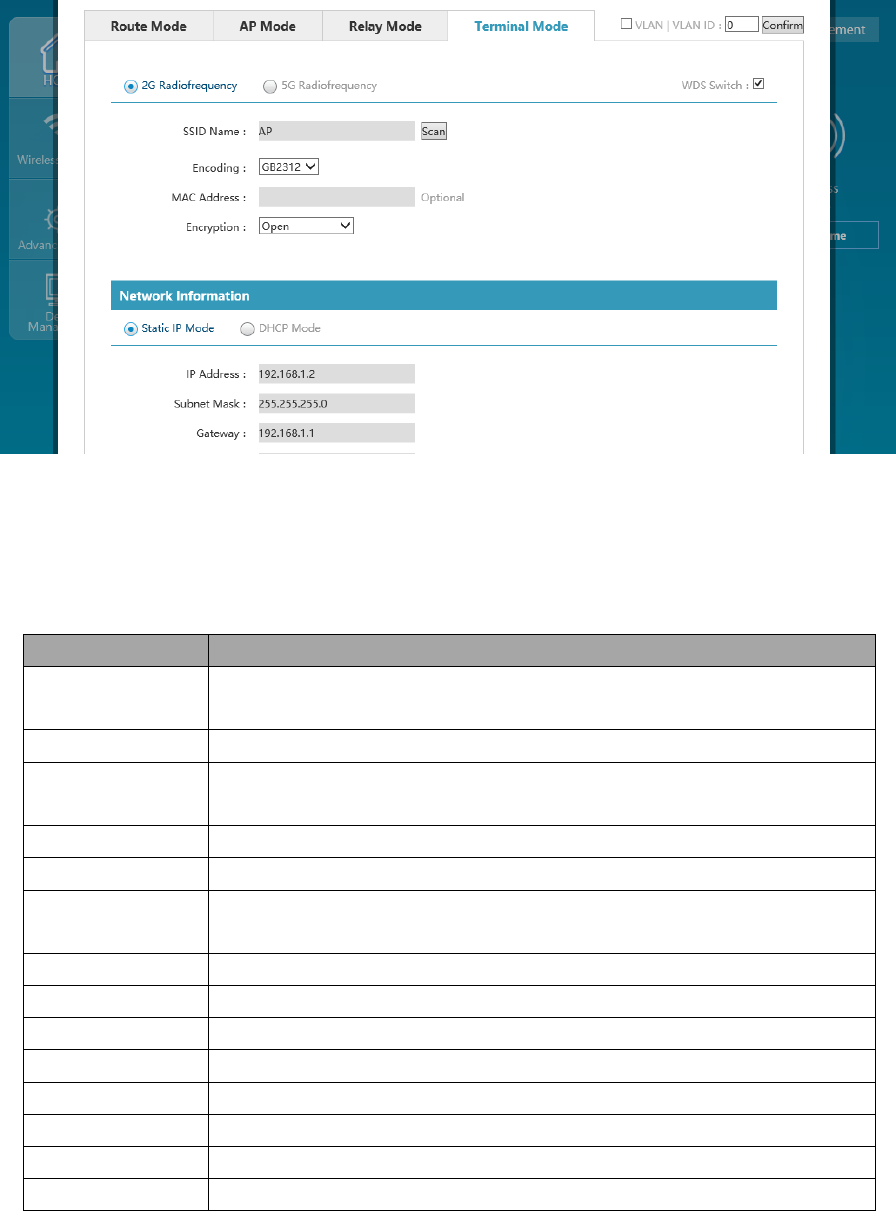
30
Figure 4.14 Terminal Mode Page Configuration
Configure relevant network of the terminal mode, with detailed configuration as shown in the following
table:
List of Network Configuration of Terminal Mode
Configuration item
Description
VLAN function
Whether the device enables VLAN, only when it is enabled, can all VLAN
configurations take effect.
VLAN ID
The VLAN ID of device management address. The VLAN ID by default is 0.
2G RF/5G RF
The working frequency band of uplink network Uplink network at the same moment can
only operate in one frequency band.
SSID name
The SSID name of uplink network
Coding way
The SSID coding way of uplink network, aiming at Chinese SSID.
MAC address
The BSSID address of uplink network (it automatically connects SSID with the same
name and strongest signal when filling gap)
Encryption way
The encryption way of uplink network (supporting OPEN, WPA-PSK and WPA2-PSK)
WDS switch
Select WDS or omnipotent relay; the default is WDS.
Static IP/DHCP
The acquisition way of network address of the device
IP address
The IP address of device
Subnet mask
The subnet mask of device
Gateway
The default gateway of device
Preferred DNS
The preferred DNS
Alternative DNS
The alternative DNS
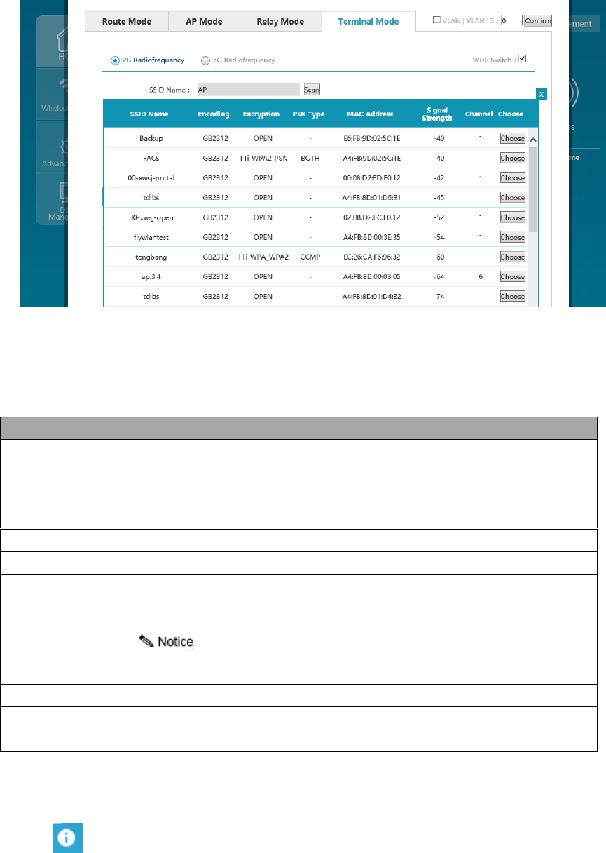
If there is need to check all wireless networks nearby of the device, it is allowed to click "Scan", and all
wireless signals around will be listed after scanning and ordered as per signal intensity from strong to weak.
31
Figure 4.15 Scanning Information of Terminal Mode
See the following table for detailed information of terminal mode upon scanning:
List of Scanning Information of Terminal Mode
Configuration item
Description
SSID name
Name of SSID of wireless network around the device
Coding way
SSID coding way of wireless network around the device There are GB2312 and UTF-8
currently.
Encryption way
Encryption state of wireless network around the device
PSK type
CCMP, TKIP and BOTH
MAC address
BSSID of wireless network around the device
Signal intensity
For signal intensity of wireless network around the device, the larger the value is, the
stronger the signal will be.
Wireless signal over -60 is suggested as the signal intensity of connection.
Channel
The working channel of wireless network around the device
Select
After clicking "Select", information about selected wireless networks will be automatically
filled into corresponding configuration items.
After clicking "Select", information of the selected wireless networks will be automatically filled into
corresponding configuration item and click "OK" to complete network configuration in terminal mode.
Click the icon of home page to view the connection information of wireless bridging.
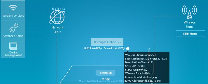
32
Figure 4.16 Connection Information of Terminal Mode
4.3 Wireless RF Setting
RF (Radio Frequency) indicates the electromagnetic frequency which has long-distance transmission
capability and can be radiated to the space. In the IEEE 802.11 WLAN protocol, 802.11b/g works in the RF band
of 2.4GHz, 802.11a/ac works in the RF band of 5GHz, and 802.11n can work in the RF bands of 2.4GHz and
5GHz simultaneously. The RF can be divided into channels (the transmission channels taking the wireless signals
as transmission media) according to different working frequency, and each channel corresponds to a frequency
range.
802.11ac is the successor of 802.11n; it has referred to and further optimized the various advantages of
802.11n; in addition to the most obvious high throughput characteristics, 802.11ac also promotes many
technologies.
Wider channel bandwidth
802.11ac can support the bandwidth of 80MHz, choose the continuously-used frequency band of
160MHz or discontinuously-used frequency band of 80+80MHz, and the promotion of bandwidth can
also increase the data subcarrier. The number of the subcarriers available for 80MHz is up to 234, but
the number available for 40MHz is only 108. Therefore, 80MHz can speed up by 2.16 times.
Higher-order modulation
802.11ac uses the orthogonal frequency-division multiplexing (OFDM) to modulate the data bit for
transmission on wireless media. 802.11ac can select 256 QAM according to situations, which enables
the data bit number of each subcarrier to increase to 8 from 6, so that the handling capacity can be
33
increased by 33%.
More empty by-pass flow and MU-MIMO
802.11ac can support 8 channels of spatial traffic at most, and the number of multiple spatial traffic
supported is optional. However, it will be most efficient when the increasing of the spatial traffic
number is combined with 802.11ac multiple-user multiple-input multiple-output (MU-MIMO) new
functions. The 802.11ac technology can support 8 channels of spatial traffic at most under the MIMO
mode, and each wireless terminal does not exceed 4 channels of spatial traffic under the multiple-user
mode.
Operative working frequency band (2.4G and 5.8G) of the device is corresponding to device models; some devices can
only operate in 2.4G, some only in 5.8G, and some in 2.4G or 5.8G.
1. Select "Wireless setting" in the home page to pop up the [Wireless setting] window.
Figure 4.17 Home Page of the Device
2. In the wireless setting window, select 2G RF or 5G RF configuration to enter the RF configuration page.
If the selected configuration is under 11ac mode, enter 5G RF configuration, and select 11ac under wireless mode
and 80MHz for channel bandwidth, as shown in the picture.
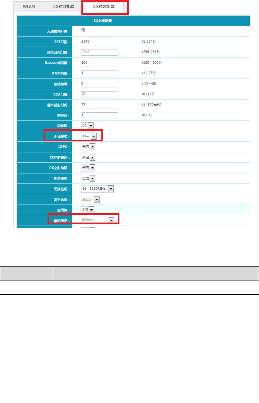
34
Figure 4.18 RF Setting Page
3. Detailed RF configuration is shown in the following table.
Table List of Detailed Configuration of RF Setting
Configuration item
Description
Wireless RF switch
For wireless RF start and close. The switch will be started if selected, otherwise is close.
RTS threshold value:
When AP sends data to certain client, the AP will send a RTS message to the client; in this way
all devices within the scope of AP coverage will not send data in specified time after receiving
RTS. After the client receives RTS, a CTS message will be sent again to ensure all devices
within the scope of coverage in the client will not send data in specified time. It needs sending
two messages with large message expenditure if using RTS/CTS to realize conflict avoidance.
Message segment
threshold
Assign fragment threshold value of frames. The basic principle of fragment is to divide a large
frame into small fragments, and each fragment could independently complete transmission and
acknowledgement. When the actual size of data package exceeds the assigned fragment
threshold value, this data package will be transmitted by fragments.
Under the wireless environment of high bit error rate, fragment threshold can be properly
lowered; by this way, only unsuccessfully transmitted part needs resending under the condition
35
of transmission failure, thereby improving the handling capacity of frame transmission.
Properly improving fragment threshold under the interference environment can reduce the time
of frame acknowledgement and improve the handling capacity of frame transmission.
Beacon frame interval
Time interval for sending the beacon frame Periodical transmission is done for beacon frame as
per assigned time interval to allow mobile user's network access to contact with other access
point device or other network control device.
DTIM interval
The DTIM (Delivery Traffic Indication Message) period when set the beacon frame
When DTIM count to 0, AP will send the multicast frame or broadcast frame in the buffer
memory
Low noise and fine
tuning
Default value is 0, and the setting range is -20- 40
CCA threshold
Improving CCA threshold of AP will reduce the receiving sensitivity.
Receiving sensitivity means that RF signal intensity reaching WLAN receiver can only be
correctly received when it is not lower than certain value.
This value needs no modification generally, and the default is adopted.
Timeout response
For timeout of data acknowledgement frame, this configuration item can be regulated for
outdoor products to reach the effect of improving handling capacity.
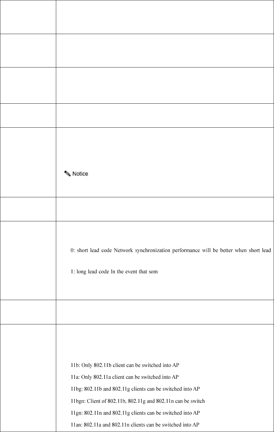
Lead code
Lead code is a set of bits located at the beginning of the data package, by which receivers could
synchronize with and prepare to receive actual data.
code is selected, so short lead code is generally selected.
e older client network cards in the network needed
to be compatible with, the long lead code can be selected for that purpose.
802.11a/802.11n(5GHz)/802.11ac(5GHz) does not support this item of configuration.
Country code
For device use country selection, different countries have different channels and power
limitations.
Wireless mode
Select the wireless working mode of router
If the RF mode of AP is to be changed, the power and channel will restore to the default
condition of corresponding mode.
ed into AP
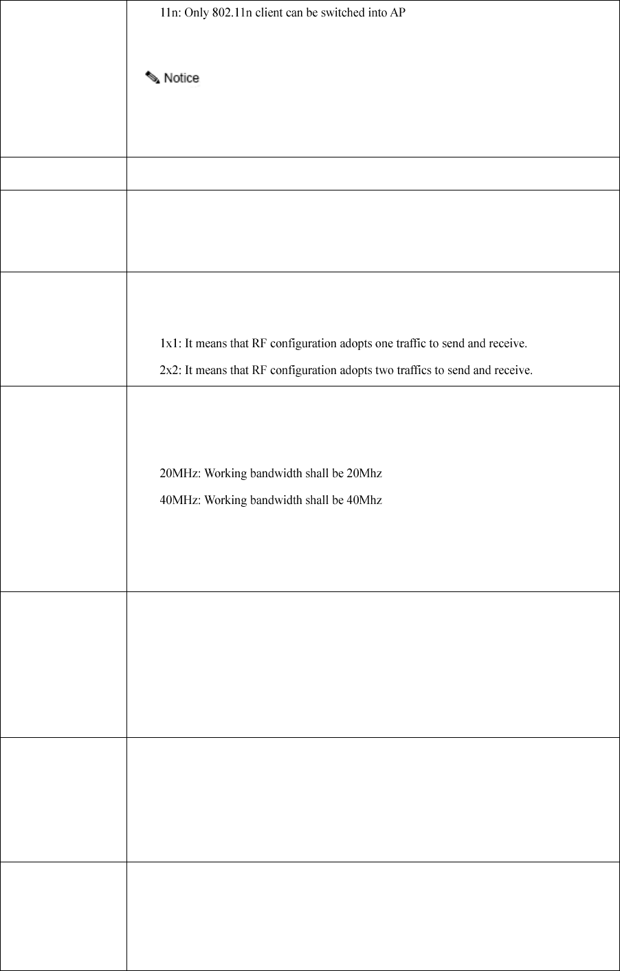
36
11ac: Only AP negotiation rate switched in by 802.11ac client can reach 1.167Gbps.
2.4G RF working mode supports 11b, 11bg, 11bgn, 11gn and 11n.
5.8G RF working mode supports 11a, 11an, 11n and 11ac
Wireless channel
Assign the working channel of RF. Channel list is determined by country code and RF mode.
Transmission power
The maximum transmission power of RF
The maximum transmission power of RF depends on the country code, channel, AP model, RF
mode and antenna type
Spatial traffic
Used for the configuration of MIMO mode of RF.
Default: Refer to the MIMO mode that has not configured with RF.
Channel bandwidth
802.11ac can form a 80MHz communication bandwidth by combining 4 bandwidths of 20Mhz
together, thus can be used as a 80Mhz bandwidth in practice, which doubles the speed and
improves handling capacity of the wireless network.
80MHZ: Working bandwidth shall be 80Mhz
By default, the bandwidth of 802.11n (5GHz) shall be 40MHz, and the bandwidth of 802.11n
(2.4GHz) shall be 20MHz
A-MPDU
The selected check box before "A-MPDU" indicates to activate the function of A-MPDU
A-MPDU aggregation frame format is adopted in standard of both 802.11n and 802.11ac, that is
to aggregate multiple MPDU into one A-MPDU and retain only one PHY head by deleting PHY
heads of other MPDU, which reduces the additional information of the PHY head of each
MPDU as well as the number of the ACK frame, resulting in lowering down the load of
protocol and effectively improving handling capacity of the network.
A-MSDU
The selected check box before "A-MSDU" indicates to activate the function of A-MSDU
A-MSDU, one new characteristic of MAC, is defined in the protocol of 802.11n and 802.11ac,
which realizes the transmission of one MSDU by aggregating multiple MSDU into one, and
reduces the transmission of additional information of MAC head of each MSDU, resulting in
improving the transmission efficiency of the MAC layer after aggregation
Package sending
interval
Select "(long)800ns" and the sending interval of the device is 800ns;
Select "(short)400ns" and the sending interval of the device is 400ns;
The GI duration of 802.11a/g is 800ns; 802.11n and 802.11ac can be configured with 800ns and
400ns. Using 400ns can improve 10% of wireless handling capacity.

37
Working rate
Configuration of working rate is realized via the index value of MCS (Modulation and Coding
Scheme). MCS is a representation form proposed by 802.11n protocol to represent the
communication rate of WLAN. MCS makes the factors affecting communication rate concerned
as column of the schedule, and MCS index as row to form a rate schedule. As a result, every
MCS actually corresponds to the physical transmission rate of a group of parameters.
auto: automatically select working rate
When the spatial traffic is 1*1, the value of MCS index takes 0-7; when MCS=7, the rate
reaches the maximum value. When the spatial traffic is 2*2, the value of MCS index takes 1-15;
when MCS=15, the rate reaches the maximum value.
When spatial traffic is 2*2, configurable MCS of different channel bandwidths is different:
When channel bandwidth is 20MHz, MCS index (0-15) is configurable.
When channel bandwidth is 40+MHz, MCS index (0-7) is configurable.
When channel bandwidth is 40MHz, MCS index (8-15) is configurable.
Dynamic frequency
adjustment
Automatic selection of channel mode (current version is not applicable)
Beacon sending rate
Set the sending rate of beacon frame
Probe suppression
Set the suppression threshold of probe, and the default configuration is 0, which shows no
suppression.
Probe suppression is mainly to discard probe frame of terminals with bad signal, which helps to
improve the performance of the device.
Protection mode
RTS/CTS: Using the way of RTS/CTS realizes 802.11g protection. When AP 1 sends data to
certain client, the AP 1 will send a RTS message to the client; in this way all devices within the
scope of AP 1 coverage will not send data in specified time after receiving RTS. After the client
receives RTS, a CTS message will be sent again to ensure all devices within the scope of
coverage in the client will not send data in specified time.
CTS-to-Self: Using the way of CTS-to-Self method realizes 802.11g protection. When AP1
needs to send a message to the client, it will apply its own address to send a CTS announcement
that AP1 will send messages; in this way, all devices within the scope of coverage of AP1 will
not send data in assigned time.
4.4 WLAN Setting
WLAN (Wireless Local Area Network) technology is one of hotspots in modern communication filed.
Compared with wired network, WLAN is relatively simple in start and implementation, besides, the cost is
relatively low. Generally, only one or more access point devices are installed, it can build WLAN covering the
38
whole building or area. However, the WLAN system is not a complete wireless system, its server and backbone
network are still installed in the wireless network and users can realize network access via wireless way.
Using WLAN solution, network operator and enterprise can provide convenient wireless access service for
user, mainly including:
User can switch in network conveniently, and visit the existing network or internet via wireless network;
Security is the largest challenge of wireless network, wireless network currently can use different
authentication and encryption ways to offer secure wireless network access service;
In wireless network, users can move freely within the scope of coverage of the network, and completely
get rid of wired restriction.
4.4.1 WLAN page configuration wizard
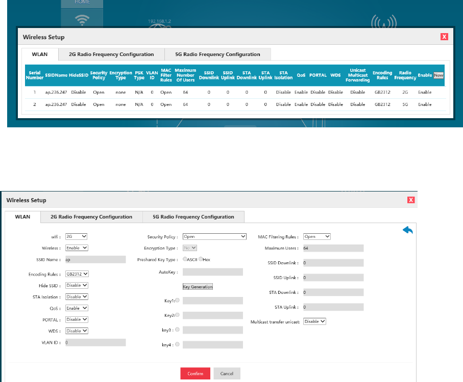
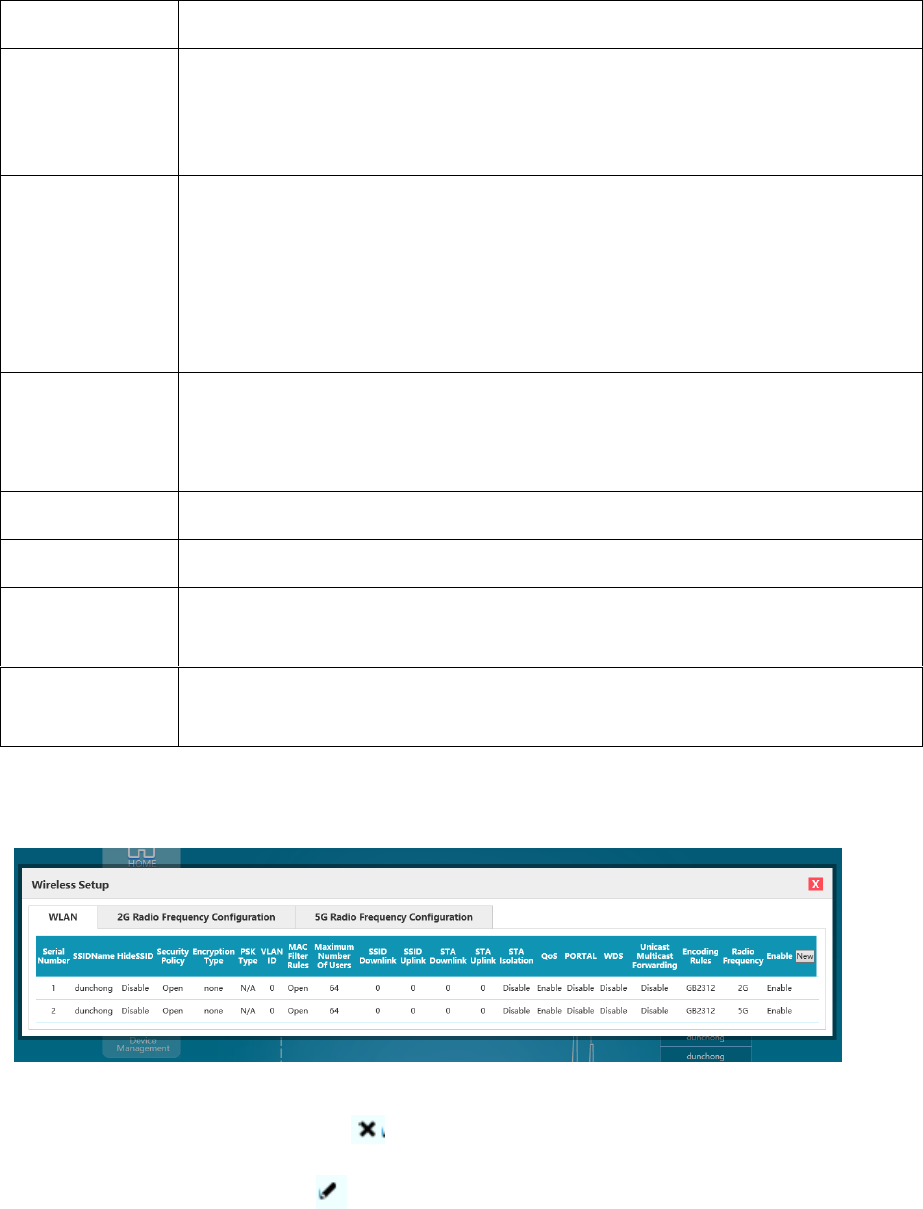
Click "Wireless setting" menu in home page and enter the WLAN page. See the figure below:
Figure 4.19 Wireless Setting Page
Click "Add" and enter the "Create SSID" page:
Figure 4.20 SSID Page
See the following list for various configurations of SSID page in details:

39
List of Configuration Parameters of SSID Page
Configuration item
Description
wifi
The working frequency band of current wireless hotspot
Wireless switch
Start and close wireless hotspots
SSID name
Wireless service name and SSID name shall be as unique as possible. In the view of security, it
shall not reflect the company name and random number sequence is also not recommended as
SSID. Random number sequence only increases Beacon's message length and application difficulty,
and will not improve wireless security.
SSID hiding
Configure whether SSID is announced in beacon frame, and it is done by default.
Open it is prohibited to announce SSID in beacon frame
Close: announce SSID in beacon frame
Hints:
After hiding SSID, the beacon frame sent by AP will exclude SSID message, and AP client must
manually configure this SSID for AP access on WLAN card.
Hiding SSID is not very important for wireless security. Allowing SSID broadcast can make AP
more easily find client at the associated stage.
STA isolation
Configure whether to make different terminals connecting this wireless hotspot visit each other.
Default configuration is close.
Open: Mutual visit between terminals under the same hotspot is prohibited.
Close: Mutual visit between terminals under the same hotspot is permitted.
Hints:
Starting STA isolation can improve the security of users in using wireless network.
Qos
Allow wireless communication to define a priority limit based on data type. Default is closed.
PORTAL
Configure wireless hotspot portal authentication switch; it can match wireless service-->portal page
customization in using.
WDS
Configure whether wireless hotspot supports WDS function. When using WDS relay, this
configuration item must be opened.
VLAN ID
Add tagged VLAN ID, which means that current wireless hotspot carries corresponding VLAN ID
Tag when sending terminal data message.
The default value is VLAN ID 0, which means that current wireless hotspot carries no Tag when
sending terminal data message.
Only when the device's VLAN function is enabled, can this configuration item take effect.
The position of configuration of device VLAN function is in the top right corner of Network Setting
page.
Security policy
Support OPEN, WAPI-PSK, WEP, WPA-EAP, WPA2-EAP, WPA-PSK and WPA2-PSK
40
Encryption type
Support CCMP/TIKP/BOTH
Coding rule
Configure the coding rule of wireless hotspot name
Hints:
In case of Chinese SSID coding way, two coding methods are recommended to be created.
MAC filtering rules
The MAC access authentication configuration switch, which matches wireless business-->MAC
blacklist and whitelist in using.
Open type: close MAC access authentication, when any terminal can be accessible to this hotspot.
Whitelist: Only MAC under MAC blacklist and whitelist can be accessed into this hotspot.
Blacklist: Only MAC under MAC blacklist and whitelist cannot be accessed into this hotspot.
Maximum user
number
The maximum number of associated clients under certain SSID
If associated clients reach the maximum number, unless some associated clients undo association
because of certain reasons, new clients cannot be accessed into this SSID.
SSID downlink
Downlink traffic control of wireless hotspot; and when the default is 0, it cannot be started
SSID uplink
Uplink traffic control of wireless hotspot; and when the default is 0, it cannot be started
STA downlink
Downlink traffic control of wireless hotspot's connection terminal; and when the default is 0, it
cannot be started
STA uplink
Uplink traffic control of wireless hotspot connection terminal; and when the default is 0, it cannot
be started
When entering various parameters and clicking "OK", there will appear the newly added SSID entry on the
SSID-VLAN page. If the SSID entry of "dunchong" is added, the figure below will appear:
Figure 4.21 Display of WLAN Page Creating
After selecting certain entry, and click " " to delete the selected entry.
After selecting certain entry, click " " to `modify the parameters of the selected entry.
SSID function can be set by clicking "Modify", "Delete" and "Add", such as security policy, whether to hide
SSID, VLAN ID, QoS, etc. It is important to notice that the AP of every SSID can be configured with different
shared keys.

41
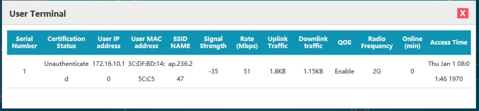
4.5 On-line Terminal List
In the place tagged with 10 in basic function information's presentation part, real-time statistics can be
realized concerning AP terminal information, including on-line terminal numbers, authentication state of each
terminal, connected SSID name, terminal MAC address, terminal IP, signal intensity, connection duration, used
traffic, access time and other information. See the following list for detail:
List of Terminal List Information
Item
Contents
Function
Authentication state
Authenticated /
unauthorized
Display whether certain user has succeeded in portal authentication;
User's IP address
X. X. X. X
Display the IP address of the user;
User's MAC
address
X: X: X: X: X: X
Display the MAC address of the user;
SSID name
SSID
Display the SSID name connected by the user;
Signal intensity
(db)
-X
Display the access signal intensity of the user; the larger the X value is, the poorer the
signal will be;
Rate (Mbps)
X
Display the negotiation rate between the user and AP; the larger the X value is, the
higher the rate will be.
Uplink traffic
X
Display user's uplink traffic and traffic unit;
Downlink traffic
X
Display user's downlink traffic and traffic unit;
QOS
Yes/No
Display whether AP has enabled QOS function;
On-line (min)
X
Display the on-line duration of the user;
Access time
Time
Display SSID's connection time of the user;
1. The basic page can display the number of AP's on-line terminals and AP's real-time uplink/ downlink
traffic (the sum of all users). See Figure 4.32.
Figure 4.22 Uplink/Downlink Traffic
42
2. It is able to check detailed information of all connection terminals after clicking the button, which does not
refresh such information real-time, but only displays the data at the very moment you click the button to open the
page; besides, the traffic information is cumulative traffic. See Figure 4.33.
Figure 4.23 Terminal Information
43
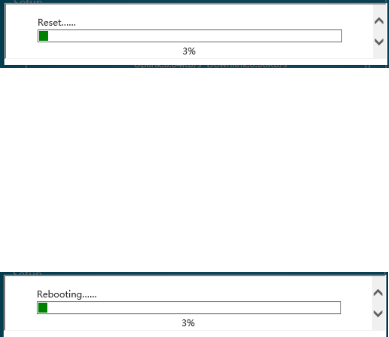
4.6 AP Recovery to Factory Setting
This button is in the lower left corner of the page and labeled with "restore" (in the place tagged with 5 of
basic information's presentation part). This function can be applied both in local management and centralized
management. After clicking, there will pop up the prompt of whether to confirm, and the configuration will be
restored after clicking "OK"; there will be corresponding progress bar in the page to show the progress, which
probably takes 2min; after switch completed, the way of IP acquisition is DHCP for AP. The management address
can be used for login management, and detailed calculation method of management address is shown in "Chapter
II Login Ways".
Note: No matter it is local management or centralized management, it will change into the default configuration under
centralized management mode after recovery into factory setting. Click "Local management" in the top right corner (in the
place tagged with 7 of basic information's presentation part) for mode switch if the local management mode is required.
Figure 4.24 Recovery To Factory Setting
4.7 AP Restart
This button is in the lower left corner (in the place tagged with 11 of basic information's presentation part),
and there will pop up the confirmation box of whether to reboot after clicking; AP reboot will be implemented
when clicking "OK" and there will be corresponding progress bar, which probably takes 2min; All configurations
will not change after reboot, and only the running time will be recounted.
Figure 4.25 Reboot
44
Chapter 5 Device Management
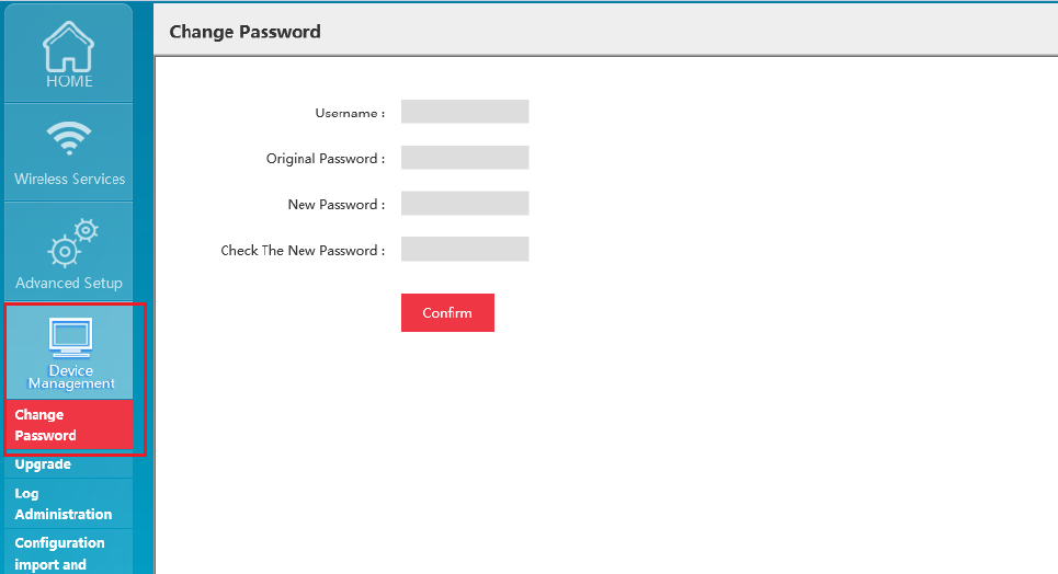
5.1 Modify Password
This function is used to modify the login password of the device management page, and facilitates users to
manage. The specific steps are as follows:
1. Log in the AP management page, click "Device Management Modify Password" in the function menu
of the home page's left side to switch to the password modification interface. See Figure 5.1:
Figure 5.1 Password Modification Page
2. Enter successively user name, original password and new password and confirm the new password to
change. There will pop up the prompt box to automatically exit after successful change and new password shall be
entered in further logging in.
Precautions:
1. User name is always "admin", which cannot be changed;
2. Original password and new password cannot be identical;
3. New password and new password confirmation must be the same;
4. Password length shall be 5-8 bits;
5. Password retrieve is not provided temporarily, if password is forgotten failing to log in, long press "Reset" of the
device to restore factory setting, and the initial password is "password".
45
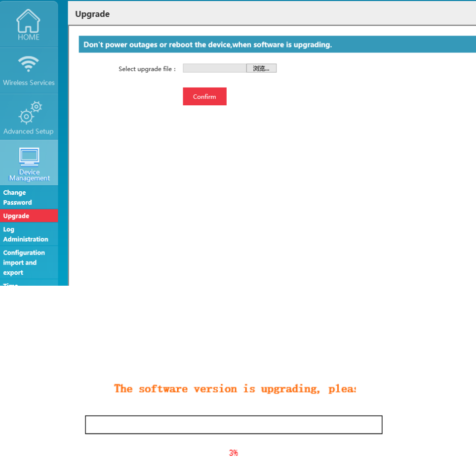
5.2 System Upgrade
The software upgrading page provides the function of access to upgrade file of target application programs
from current user's host (local computer), upgrade software version for the device to solve defects in current
version, improve existing functions, add new functions, etc., and promote the experience effect of users.
1. This function is opened by clicking "Device management Upgrade" in the main page. See Figure 5.2:
Figure 5.2 Upgrade Page
2. Click "Browse", select the upgrade file in local computer, and then click "OK" to upgrade; there is
progress prompt on the page. See Figure 5.3:
Figure 5.3 Progress Bar of Upgrade
Precautions:
1. Upgrade file shall be obtained from company technicians, otherwise, successful upgrading cannot be ensured;
2. Upgrade file is not in common use among AP with different models and it needs to confirm the model and select
46
corresponding files to upgrade before operation;
3. There are relevant codes for the designation of upgrade files. Please do not change the file name at will;
4. The same version will not be upgraded;
5. The upgrade files wrongly selected will not be upgraded;
6. Upgrading process will take some time, during which it needs to stay at the upgrade progress page and is not allowed
to turn off the power of the device, or it will lead to upgrade failure of the device;
7. It will automatically skip into the new version login page after successful upgrade, and it needs to log in again;
8. It is allowed to look over the version No. of the device at the lower position of the middle of the device management
page to check whether the upgrade is successful.
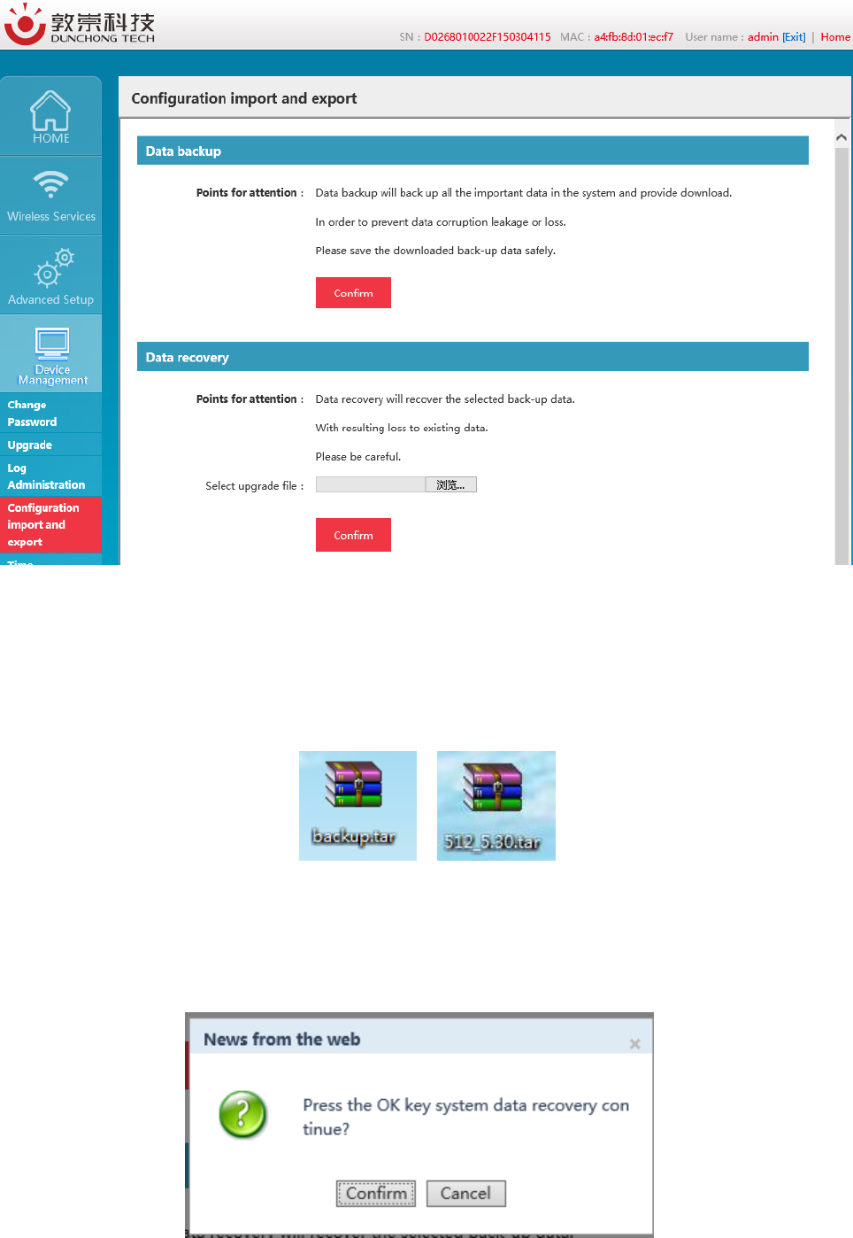
5.3 Configuration Management
The configuration import/ export function allows users to backup and restore configuration for the device,
and prevent some misoperation from causing configuration loss or change. Different configurations can be also
done based on different scenarios, and relevant backup to local computer will be done. In later configuration
switch, it does not need to reconfigure, but directly import saved configuration files for switchover;
1. This function is opened by clicking "Device management Configuration import/ export" in the main
page. See Figure 5.4:
47
Figure 5.4 Page of Configuration Import/ Export
2. Data backup: This function is for configuration backup. Click "OK" to download and save configuration
files to local computers. The default configuration file's name is "backup.tar", which can be modified based on
demands, but the postfix must be ".tar", such as "WA512.tar";
Figure 5.5 Data Backup
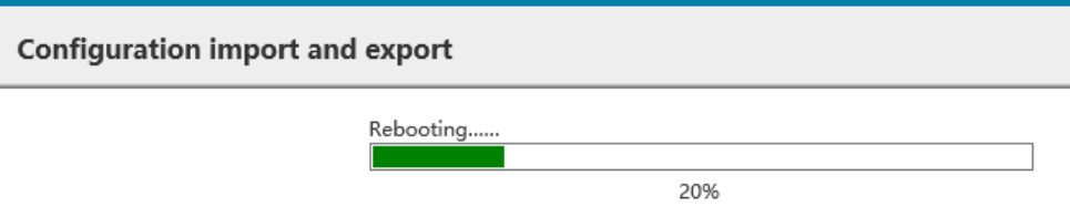
3. Data recovery Click "Browse", select correct backup files in popped up window, click "OK" and there will
pop up prompts; upon confirmation, the configuration can be restored.
48
Figure 5.6 Data Recovery
Figure 5.7 Recovery and Restart
- 49 -
Chapter 6 Example of Typical Networking Configuration
6.1 Example of Typical Configuration (Centralized Management + AP Mode)
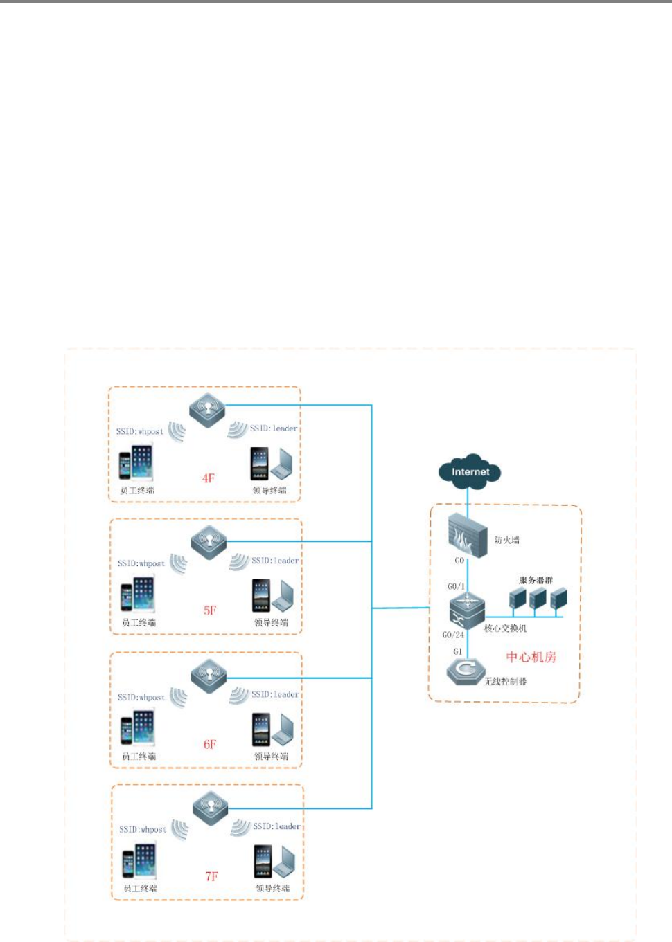
6.1.1 Networking requirements
When a company applies for operator WLAN broadband and uses WA722M-E as the enterprise access
device, which uses WAC4006 as the WLAN access controller, the specific requirements as follows shall be
satisfied:
Figure 6.1 Topological Graph of Networking under Centralized Mode
Totally 20 sets of WA722M-E are deployed network-wide and wireless coverage will be

- 50 -
realized for Floor 4-7 in office building in phase 1;
FIT architecture is adopted network-wide, AP supplies power through POE modules, floor
H3C is accessed to the exchanger as the access device and then connects with the core exchanger in the
central apparatus room, with AC hanging beside core exchanger;
AP management address and dynamic acquisition ways of user IP;
AP and AC belong to the same management VLAN1, with the AC management address being
172.20.40.101, wireless terminal belonging to vlan10, business address being 172.20.60.101 and
gateway address being 172.20.60.1;
The network is set up with 2 SSID, with whpost adopting WP2-PSK authentication for general
staff and leader adopting WP2-PSK authentication for leaders.
Due to the bandwidth limitation in whpost, downlink traffic is 256KB; and due to the
bandwidth limitation in leader, downlink traffic is 2MB.
6.1.2 Precautions of configuration
20 sets of AP, with the quantity of licenses of AC no less than 20;
In the access policy of AP upgrade, the device of WA722M-E shall be added into WAC4006;
Channel plan shall be made according to the wireless environment on site and there is no detailed configuration
for this part in this manual.
Networking demand is achieved by the combination of management VLAN and business VLAN as well as trunk
port set up for AC port, exchanger ports connected with AC and all the ports of POE exchangers connected with
AP, with access to vlan 10 (vlan1 is the vlan by default without setting default);
6.1.3 Configuration steps
1) Configuration of AP
AP is switched into centralized management mode: There are two ways to switch modes: one is through page,
that is, to switch local and centralized modes in the home page; Directly enter the network address of AC when
modes switching.
- 51 -
Figure 6.2 Web Centralized Management Switching
And the other is through background command, with the configuration as follows:
WA722M-E# set_apap_mode 1
AP can be on line through the distribution address of DHCP: can log in the device via page, and switch the
address in the network management with the configuration as follows:
Figure 6.3 Network Configuration
There is no need to set up each device with the centralized management mode as the factory default. It only needs to

- 52 -
access AP device into network, at the same time of configuration of option43 by DHCP server.
2) Configuration of AC
Configuration of AC is as shown in AC User's Manual, which will not be described in detail herein.

- 53 -
Chapter 7 Fault Elimination
How should users obtain the MAC address of the device?
The MAC address is the unique identifier of network device and there are two ways to obtain as follows:
At the bottom of each device, there is a small label with the MAC address of the device.
Alternatively, users could check the basic information and get the MAC address of the device by
logging in the Web management page of the device.
Why STA cannot be connected with AP?
Generally speaking, the steps of STA connection include the searching of available AP, authentication,
connection, etc., and if STA cannot be connected with AP, it is feasible to investigate from the following
several aspects:
Whether the channels supported by STA and by AP are the same. The STA with channels
unsupported by AP cannot find the AP. In this case, AP channels shall be replaced.
STA does not use the same authentication and encryption ways as that of AP. Given this, STA will
fail to pass authentication and cannot be connected with AP.
The interference of identical devices. Check whether there are wireless devices around; and if
possible, try to close such devices to check if the situation can be improved. Shield or adjust the
position of interfering devices.
The interference of other devices. Check whether there is interference sources around, such as
microwave ovens and other 2.4G high-power device, which could seriously influence the normal
performance of the device. If possible, try to close such devices to check if the situation can be
improved.
STA and AP are not compatible. Perhaps STA cannot satisfy 802.11 protocol, thus restraining its
connection with AP.
Why is the bandwidth not so high after the establishment of wireless network?
The reasons why the bandwidth of the device is not so high may be result from the interference of the
environment in most cases, or the reduction of transmission power of aging devices. It is allowed to try
the following adjustment methods:
Wireless channel Try to select other channels, which may significantly increase rate;
Interference of wireless. Check whether there are wireless devices around; and if possible, try to

- 54 -
close such devices to check if the situation can be improved. Shield or adjust the position of
interfering devices.
Check the antenna. Check whether the antenna is loose.
Check signal intensity. Check the signal intensity of STA connected with AP; if it is very weak, it
may be resulted from antenna looseness, or the reduction of output power of aging device.
Check network card. Perhaps the power of network card itself is very low and it's feasible to try to
approach to AP to test bandwidth.
Wireless network works properly after foundation, but links start to be unstable after certain periods
of application, such as delay increasing, package loss and so on.
Perhaps the wireless environment of device operation is disturbed, when it is feasible to eliminate such
faults by the steps as follows:
Check if the connection of device parts are proper (such as wired network and antenna connection).
Restart the device after a power failure.
Reconfiguration after restoring the default values of device;
Check if there are virus invasion in AP devices at wired or wireless ends;
If the problem remains after above processing, please contact with the distributor.
Why is the negotiation rate of the laptop only 54M after connected to wireless?
In normal networking test, the 144M bandwidth mode with issued traffic as 11n is frequently discovered;
however, upon terminal connection, the negotiation rate of certain network card remains to be 54M; then
it needs to initiate the Qos function of WLAN policy and the negotiation rate of these cards will increase
to 144M.