Hangzhou Gubei Electronics Technology 3301-SBSL Wi-Fi Module User Manual
Hangzhou Gubei Electronics Technology Co.,Ltd Wi-Fi Module Users Manual
Contents
- 1. Users Manual
- 2. User manual_1
Users Manual

BiTrend™ EssentialSeriesWi-Fi Module
Datasheet
WT1SBSL

1www.ibroadlink.com
Hangzhou Gubei Electronics Technology Co., Ltd.
Copyright Information
The information contained in this document is the proprietary information of Hangzhou Gubei
Electronics Technology Co., Ltd. (hereinafter referred as BroadLink). Further, no portion of this
document may be altered or edited in any form or by any meanswithout the prior written
consent of BroadLink, the copyrightholder.
Further BroadLink reserves the right to make modifications, additions anddeletions to this
document due to typographical errors, inaccurate information, orimprovements to products
mentioned in the document at any time and without notice. Such changes will, nevertheless be
incorporated into new editions of this document or published as errata sheet.
Version History
V 1.0.0
22/01/2016
1stissue of preliminary document

2www.ibroadlink.com
Table of Contents
1. Introduction ................................................................................................................................. 3
1.1 Overview ............................................................................................................................ 3
1.2 Applications ....................................................................................................................... 4
1.3 Key Features ...................................................................................................................... 4
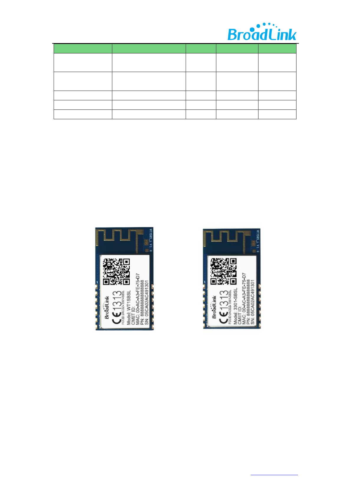
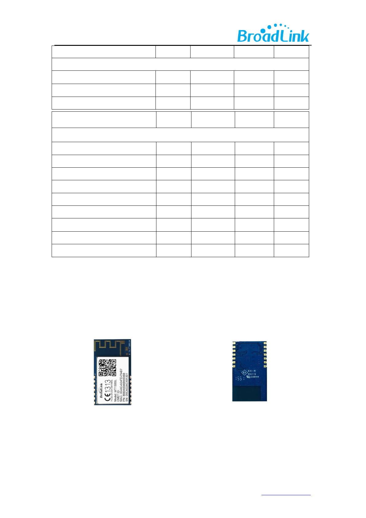
2. Product Overview ....................................................................................................................... 5
2.1 Product Picture ................................................................................................................. 5
3. Electrical Characteristics ............................................................................................................. 6
3.1 Absolute Maximum Ratings – Voltage & Current ........................................................ 6
3.2Current consumption ........................................................................................................ 7
3.3 Absolute maximum ratings – Temperature ................................................................... 7
3.4Absolute maximum ratings – ESD ................................................................................... 7
4. RF Characteristics ........................................................................................................................ 8
4.1Basic Characteristics .......................................................................................................... 8
4.2 IEEE802.11b Mode ............................................................................................................ 8
4.3 IEEE802.11g Mode ............................................................................................................ 9
4.4 IEEE802.11n 20Mhz Bandwidth Mode ......................................................................... 10
4.5 IEEE802.11n 40Mhz Bandwidth Mode ......................................................................... 11
5. Mechanical Characteristics ...................................................................................................... 12
6. Module Interfaces ..................................................................................................................... 13
6.1 PIN Layout ....................................................................................................................... 13
6.2 PIN Definitions ................................................................................................................ 14
7. Reference Design ...................................................................................................................... 15
8.1 Antenna Selection .......................................................................................................... 16
8.2 Minimizing Radio Interference ..................................................................................... 17
8.3 Specification of On-Board Antenna ............................................................................. 18
Appendix A Glossary(Quentin respible) ............................................................................... 19
Appendix B Reference paper(Quentin respible) .................................................................. 21
Contact Us ..................................................................................................................................... 22

3www.ibroadlink.com
1. Introduction
1.1 Overview
BiTrend™ Essentialis the industrial leading 2.4Ghz 802.11 b/g/n embedded Wi-Fi module which
delivers unmatched performance and codeless development in a compact package, providing
a quick, easy and cost effective way for developers and manufacturers to add Wi-Fi connectivity
for home automation, lighting control, energy efficiency and other IOT applications.
BiTrend™ Essential family combines a 2.4Ghz 802.11 b/g/n radio transceiver with a 32-bit
microprocessor and embedded with MAC, baseband processing and optimized Wi-Fi network
stack. It is an ideal solution for developers and manufacturers with limited RF and embedded
programming expertise as it significantly reduces RF design time and removes the burden of
testing and certification.
Benefitted from BroadLink’s turn-key solution, BiTrend™ Essential is an ideal solution for
developers with limited Wi-Fi or RF expertise or for those seeking faster time to market. It
reduces RF design time and removes the burden of testing and certification. BiTrend™ Essential
is fully compliant with IEEE 802.11 b/g/n standard and certified with CE, FCC and RoHS.
BiTrend™ Essential is a highly integrated Wi-Fi SoC(system on Chip) single chip, which
supportsIEEE802.11b/g/n single stream, providing GPIO for intelligent control, and UART
interfaces for device communication.
BiTrend™ Essential has 8Mbits flash and integrates power amplifier, low noise amplifier, and RF
switch to reduce the module size and RF design capability required. And also integrate power
manage unit for single 3.3V power source for cost effective design.
BiTrend™ Essential embedded 32-bit RISC MCU for 802.11b/g/n drivers, supplicant, TCP/IP
protocol stack, and networking applications, can be operated in station mode and softAP mode.
The WT1SBSL is an ideal solution for embedded device to enable networking service with
minimized design effort.
RF
receiver
RF
transmitter
Baseband
MAC /
Packet
buffer /
security
engine
UART
System
control
RF_IN
RF_OUTP
RF_OUTN
UART
GPIO/LED
Figure 1. WT1SBSL block diagram

4www.ibroadlink.com
1.2 Applications
Smart home appliances
Remote Control
Medical/Health Care
Network consumer devices
1.3 Key Features
a. Support IEEE802.11b/g/n
Frequency Range
2.412 GHz - 2. 462GHz
Wi-Fi Standard
IEEE 802.11 b/g/n
Transmitter Power
802.11b:17dBm±0.5
802.11g:18dBm±0.5
802.11n:16dBm±0.5
MIN Receiver Sensitivity
802.11b<-78dBm
802.11g<-68dBm
802.11n<-66dBm
Data rate
11M@802.11b, 54M@802.11g, MCS7@802.11n
Security
Encryption Standard:WEP/WEPA/WPA2
EncryptionAlgorithm:WEP64/WEP128/TKIP/AES
Wi-Fi Modes
STA/AP
b. Support UARTtransparent transfer
c. Support STA\AP
d. Patent SmartConfig™ technology
e. Support IPv4, TCP/UDP/ DNS/DHCP
f. PCB printed antenna
Antenna type
PCB printed ANT
g. Power source: 3.3V
h. Peripherals:
1*UART
5*GPIO
1*RESET
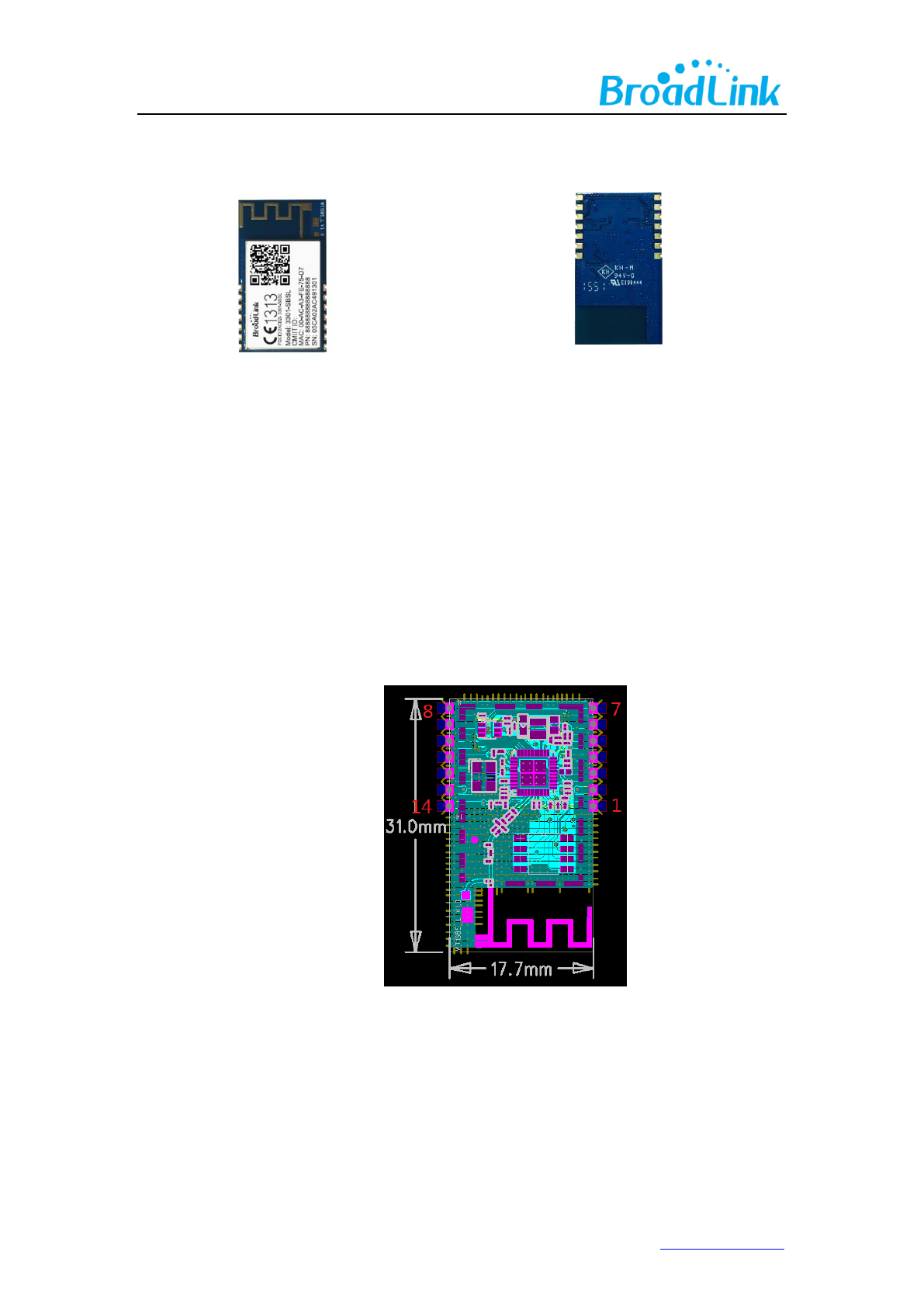
i. Dimension 31mm*17.7mm*3.6mm
j. ESD: 2KV
k. Absolute maximum ratings
6www.ibroadlink.com
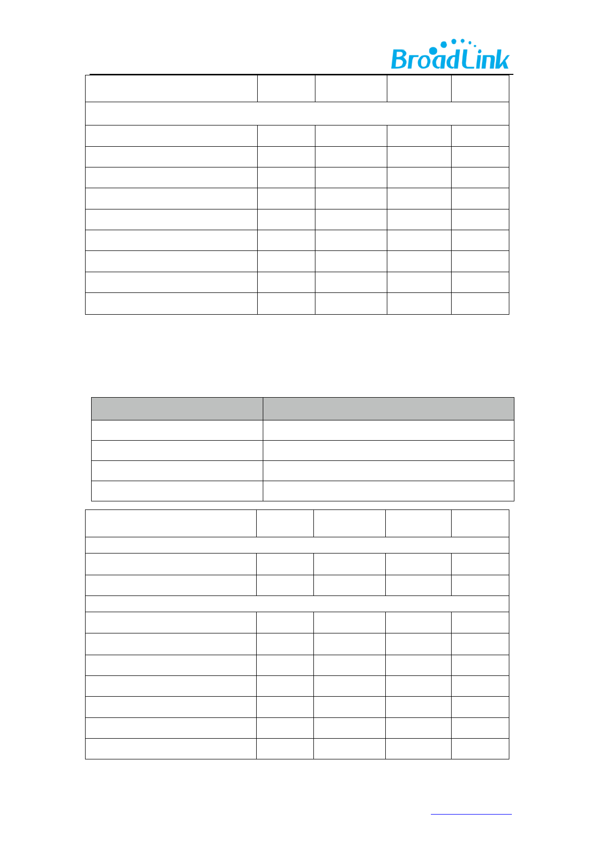
3. Electrical Characteristics
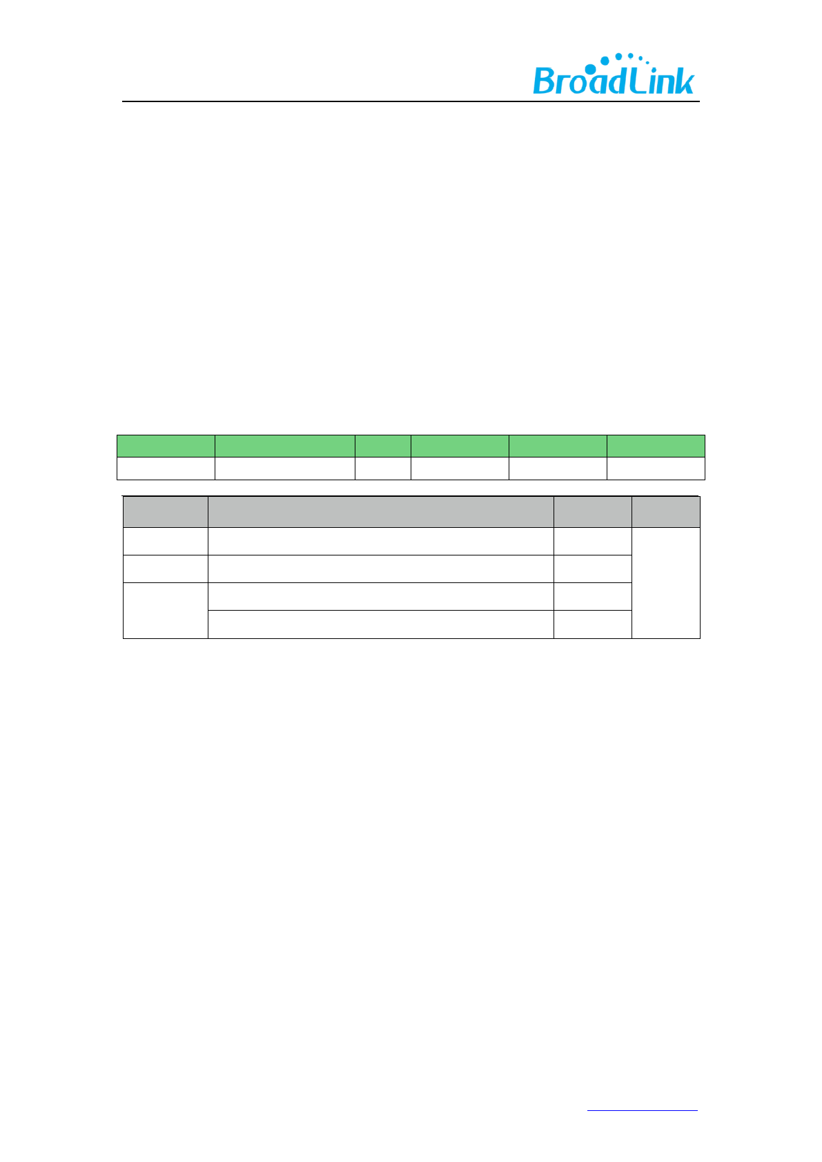
3.1 Absolute Maximum Ratings – Voltage & Current
Using products above the absolute maximum ratings may cause permanent damage to the
device. These are maximum ratings only and functional operation of the device at these
conditions is not implied. Exposure to maximum rating conditions for extended periods may
affect the reliability of the device.
Symbol Rating MIN TYP MAX Unit
VDD33 3.3V Supply Voltage 2.97 3.3 3.63 V
Symbol Ra
ting
s Max Unit
I
VDD Total current into VDD power lines (source) 90
mA
I
VSS Total current out of VSS ground lines (sink) 90
I
IO
Output current sunk by any I/O and control pin 10
Output current source by any I/Os and control pin 10
7www.ibroadlink.com
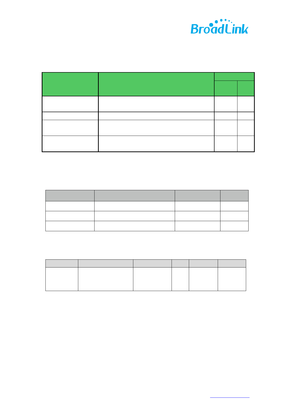
3.2Current consumption
Symbol Condition
Performance
TYP Unit
IRF
IDLE mode 80 mA
IRF RX Active, HT40, MCS7 151 mA
IRF TX HT40, MCS7
@ 15dBm(pulse) 210 mA
IRF TX CCK
11Mbps @ 18dBm(pulse) 250 mA
Note: All result is measured at the antenna port and VDD33 is 3.3V
3.3 Absolute maximum ratings – Temperature
Symbol Ra
ti
ng
s
Max Unit
T
STG Storagetemperature –40 to+125
℃
T
AWorkingtemperature -10 to+70
℃
Humidity
Non condensing, relative humidity 90%(RH)
3.4Absolute maximum ratings – ESD
Symbol Ratings Conditions Class Max Unit
V
ESD(HBM)
Electrostatic discharge
voltage
(human body model)
TA = +25 °C
conforming to
JESD22-A114
2 2000 V
8www.ibroadlink.com
4. RF Characteristics
4.1Basic Characteristics
Item
Specification
OperatingFrequency
2.412 GHz - 2.462 GHz
Wi-FiStandard
IEEE 802.11b/g/n
ModulationType
11b: DBPSK, DQPSK,CCK for DSSS
11g: BPSK, QPSK, 16QAM, 64QAM for OFDM
11n: MCS0~7,OFDM
Data Rates
Antennatype
PCBprintedANT
4.2 IEEE802.11b Mode
Item
Specification
ModulationType
DSSS/CCK
Frequencyrange
2412MHz~2462MHz
Channel
CH1 toCH11
Datarate
1,2,5.5,11Mbps
TX Characteristics
Min
Typical
Max.
Unit
Transmitter Output Power
11bTarget Power
17
dBm
Frequency Error
-20
+20
ppm
Constellation Error( peak EVM)@ target power
1~11Mbps
-17
-10
RX Characteristics
Min
Typical
Max.
Unit
Minimum Input Level Sensitivity
1Mbps (FER≦8%)
95
-83
dBm

9www.ibroadlink.com
2Mbps (FER≦8%)
-20
-93
-80
dBm
5.5Mbps (FER≦8%)
-91
-79
dBm
11Mbps (FER≦8%)
-89
-76
dBm
Maximum Input Level (FER≦8%)
-10
dBm
4.3 IEEE802.11g Mode
Item
Specification
ModulationType
OFDM
Frequencyrange
2412MHz~2462MHz
Channel
CH1 toCH11
Datarate
6,9,12,18,24,36,48,54Mbps
TX Characteristics
Min
Typical
Max.
Unit
Transmitter Output Power
11gTarget Power
18
dBm
Frequency Error
-20
+20
ppm
Constellation Error( peak EVM)@ target power
6Mbps
-5
dB
9Mbps
-8
dB
12Mbps
-10
dB
18Mbps
-13
dB
24Mbps
-16
dB
36Mbps
-19
dB
48Mbp
-22
dB
54Mbps
-25
dB
Transmit spectrum mask
@11MHz
20
dBr
@20MHz
-28
dBr
@30MHz
-40
dBr
RX Characteristics
Min
Typical
Max.
Unit
Minimum Input Level Sensitivity
6Mbps
-90
-83
dBm

10www.ibroadlink.com
9Mbps
-
-88
-80
dBm
12Mbps
-86
-79
dBm
18Mbps
-85
-76
dBm
24Mbps
-82
dBm
36Mbps
-79
dBm
48Mbps
-75
dBm
54Mbps
-72
dBm
Maximum Input Level (FER≦10%)
-20
dBm
4.4 IEEE802.11n 20Mhz Bandwidth Mode
Item
Specification
ModulationType
OFDM
Frequencyrange
2412MHz~2462MHz
Channel
CH1 toCH11
Datarate
MCS0/1/2/3/4/5/6/7
TX Characteristics
Min
Typical
Max.
Unit
Transmitter Output Power
11n HT20 Target Power
16
dBm
Frequency Error
-20
+20
ppm
Constellation Error( peak EVM)@ target power
MCS0
-5
dB
MCS1
-10
dB
MCS2
-13
dB
MCS3
-16
dB
MCS4
-19
dB
MCS5
-22
dB
MCS6
-25
dB
MCS7
-28
dB
Transmit spectrum mask
@11MHz
-20
dBr
@20MHz
-28
dBr
@30MHz
-40
dBr
11www.ibroadlink.com
RX Characteristics
Min
Typical
Max.
Unit
Minimum Input Level Sensitivity
MCS0
-89
dBm
MCS1
-
-86
dBm
MCS2
-84
dBm
MCS3
-82
dBm
MCS4
-78
dBm
MCS5
-74
dBm
MCS6
-72
dBm
MCS7
-69
dBm
Maximum Input Level (FER≦10%)
-30
dBm
4.5 IEEE802.11n 40Mhz Bandwidth Mode
Item
Specification
ModulationType
OFDM
Frequencyrange
2422MHz~2452MHz
Channel
CH3 toCH9
Datarate
MCS0/1/2/3/4/5/6/7
TX Characteristics
Min
Typical
Max.
Unit
Transmitter Output Power
11n HT40 Target Power
16
dBm
Frequency Error
-20
+20
ppm
Constellation Error( peak EVM)@ target power
MCS0
-5
dB
MCS1
-10
dB
MCS2
-13
dB
MCS3
-16
dB
MCS4
-19
dB
MCS5
-22
dB
MCS6
-25
dB
12www.ibroadlink.com
MCS7
-28
dB
Transmit spectrum mask
@11MHz
-20
dBr
@20MHz
-28
dBr
@30MHz
-40
dBr
RX Characteristics
Min
Typical
Max.
Unit
Minimum Input Level Sensitivity
MCS0
-86
dBm
MCS1
-
-83
dBm
MCS2
-81
dBm
MCS3
-79
dBm
MCS4
-75
dBm
MCS5
-71
dBm
MCS6
-69
dBm
MCS7
-66
dBm
Maximum Input Level (FER≦10%)
-30
dBm
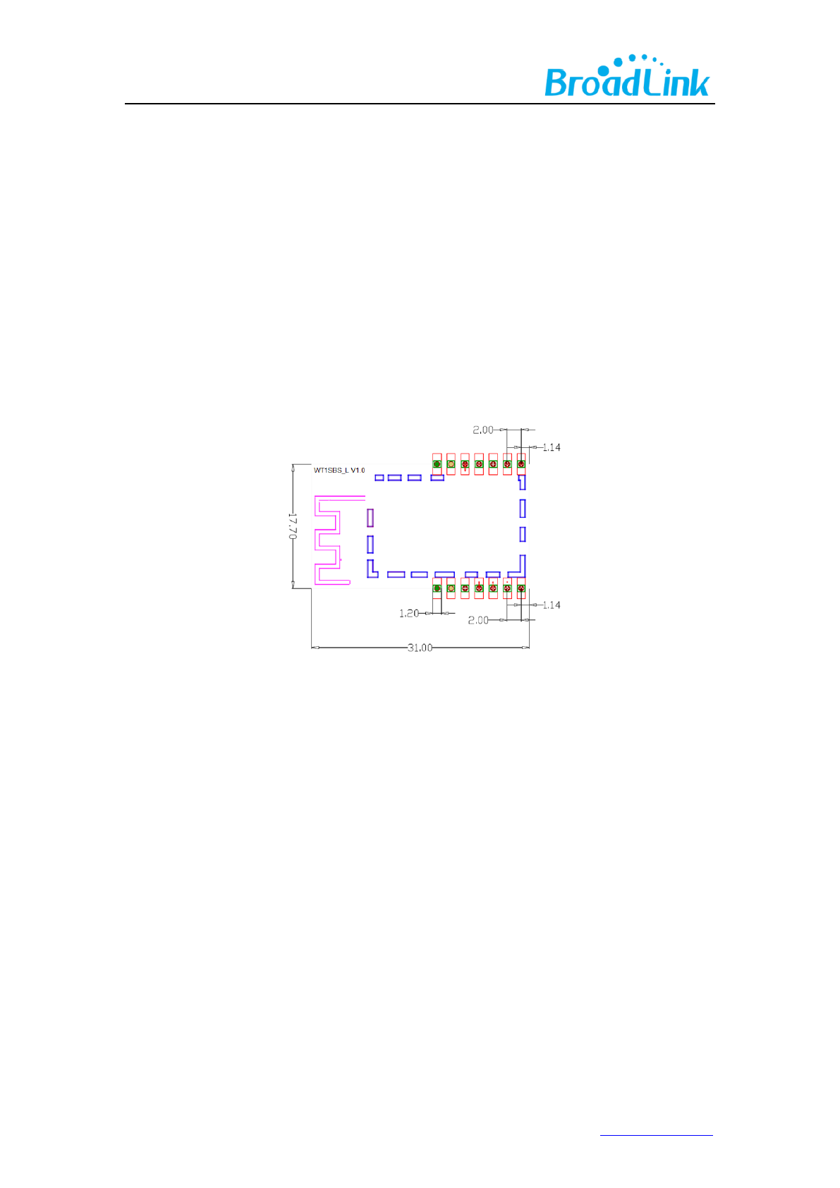
5. Mechanical Characteristics
Figure2.
WT1SBSL
topview(Metricun
it
s
)

14www.ibroadlink.com
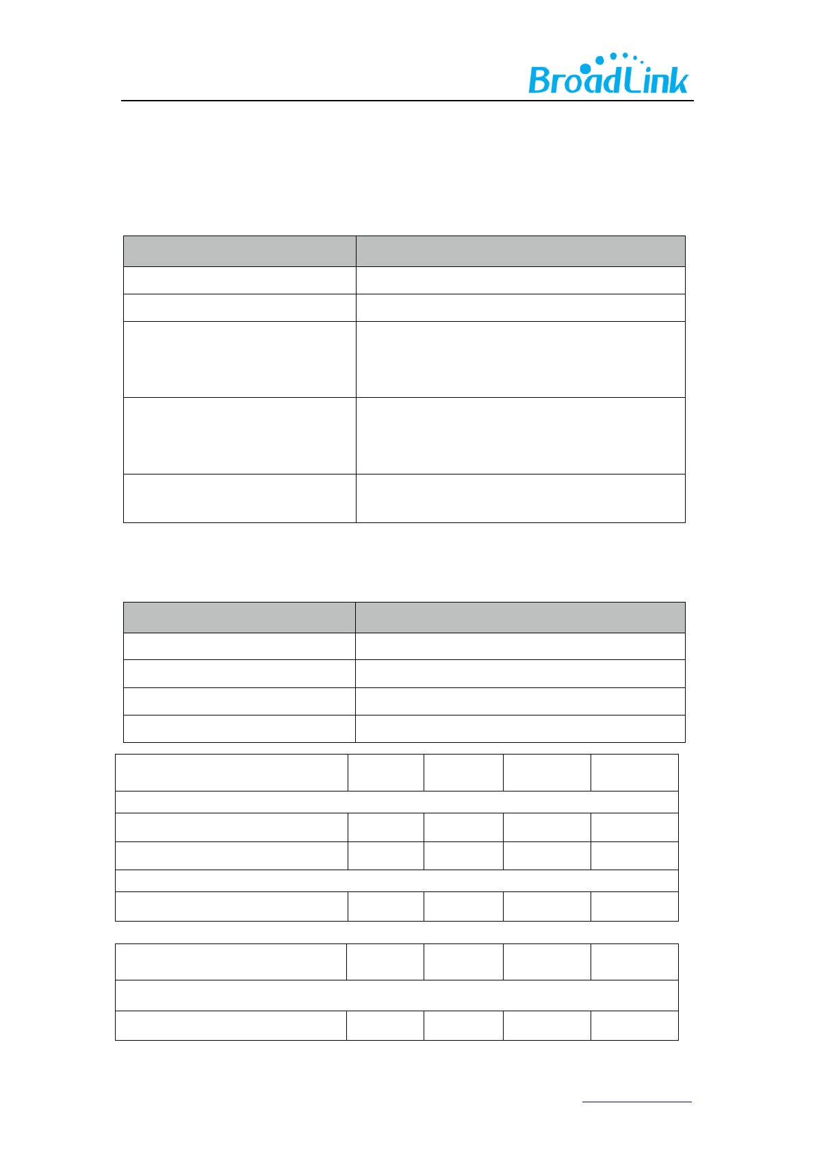
6.2 PIN Definitions
PIN Assignment
PIN
PIN NAME
NOTE
Pin1
GND
Pin2
VCC
3.3V
Pin3
RST_N
Module software reset,Available
at low level
Pin4
UART_TX
UART Only
for Passthrough
Pin5
UART_RX
Pin6
GPIO3
Pin7
GPIO4
Feed watchdog
Pin8
GPIO4
Feed watchdog
Pin9
GPIO3
Pin10
GPIO2
Pin11
GPIO1
Module software reset, Available
at High level
Pin12
GPIO0
Usually use as Wi-Fi LED
Pin13
VCC
3.3V
Pin14
GND
Type:
15www.ibroadlink.com
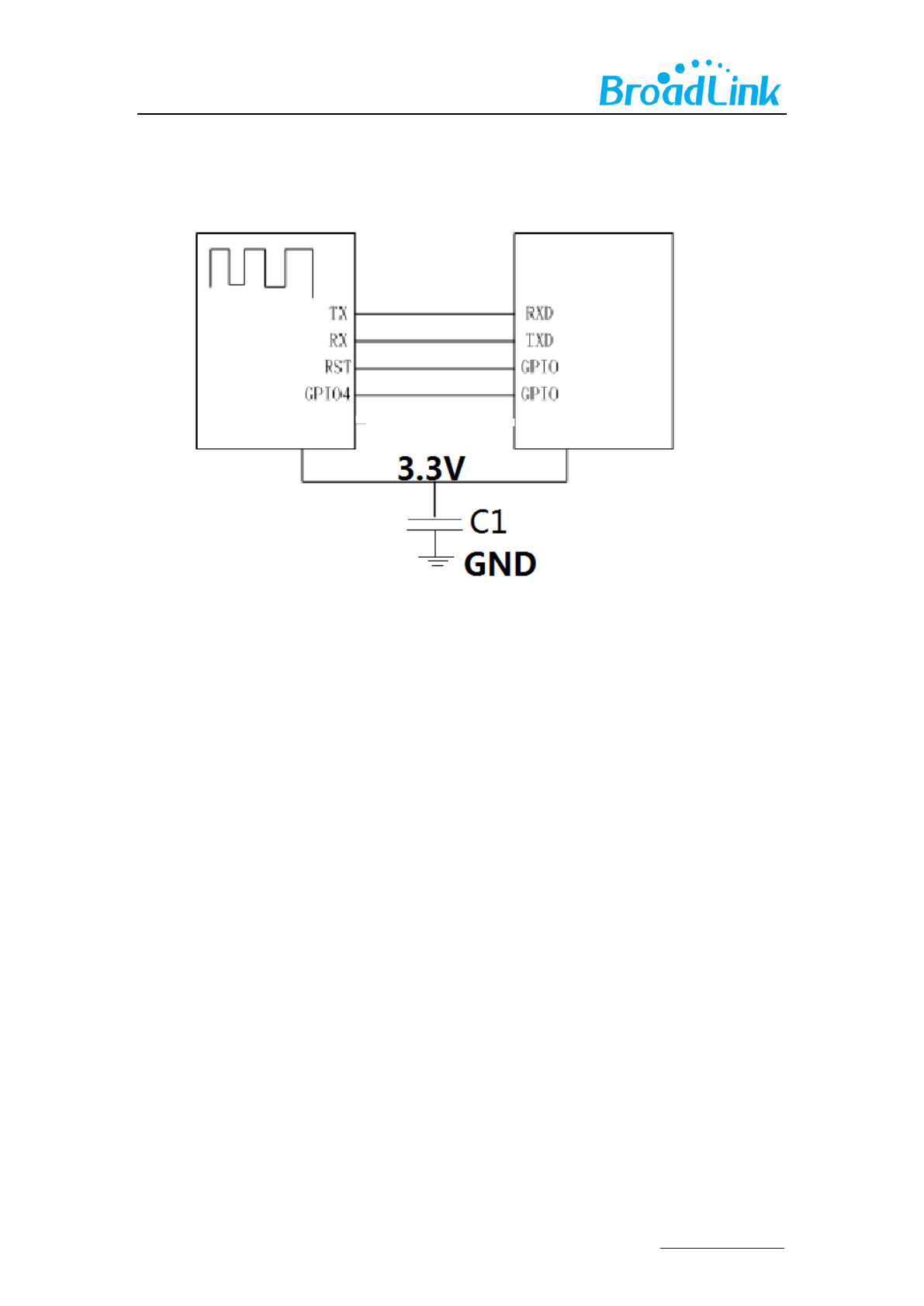
7. Reference Design
In addition to the standard serial port,the peripheral MCU also need to provide two GPIO pins
to connect with the GPIO4 pin and the RST pin of the WIFI module respectively,when the WIFI
module works properly,the GPIO4 pin will keep outputting message of dog feeding,if the
peripheral MCU did not receive the message,the module will reset and restart through pulling
down the RST pin by the other GPIO pin.
If the peripheral MCU uses power source of 5V,it needs to add a level switching circuit in the
connection of the serial port and the related circuit.
The module needs a large current about 250mA when transmitting data,please ensure that the
power source can provide sufficient current.
WIFI MODULE
Peripheral MCU
16www.ibroadlink.com
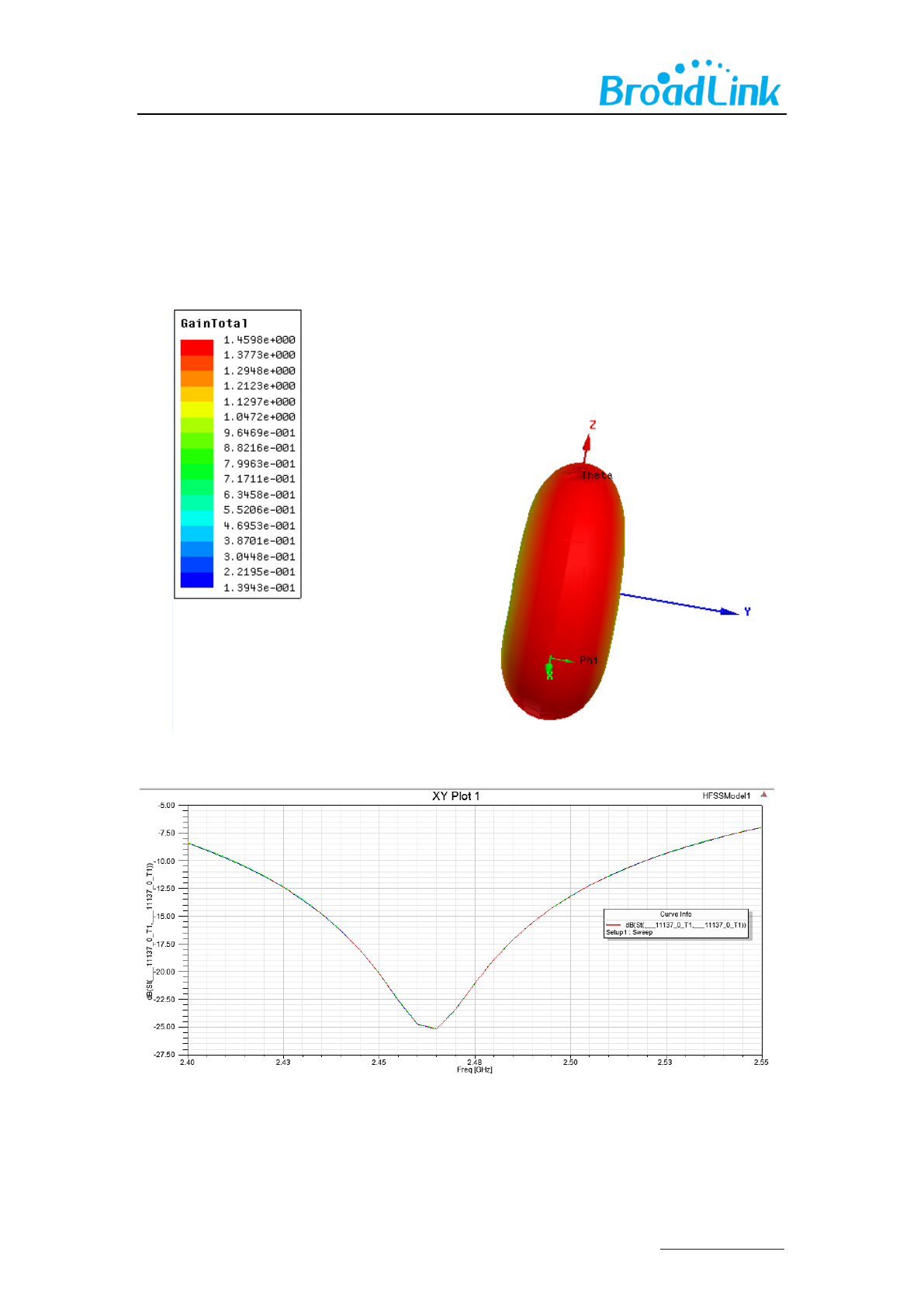
8. AntennaCharacteristics
8.1 Antenna Selection
The WT1SBSL supports on-board PCB printed antenna.When the Operating Frequencyis
between 2.4G~2.5GHz, S11 of antenna port is less than-10dB and peak gainis 1.46dBi.
Figure 7. Antenna radiation pattern simulation
Figure 8. Antenna port S11simulation curve
In practical use, WT1SBSL is welded on user’s boardand value of S11 has some changes.
17www.ibroadlink.com
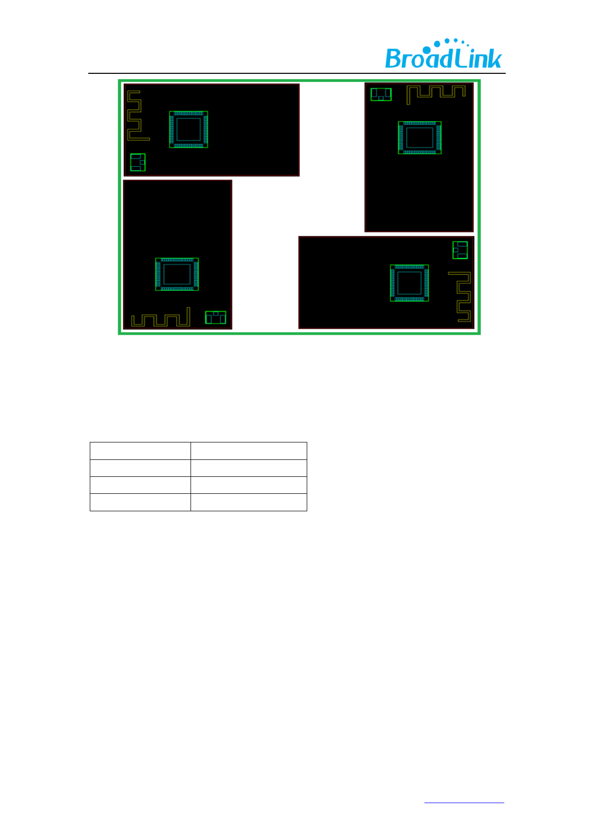
8.2 Minimizing Radio Interference
When integrating the Wi-Fi module with on board PCB printed antenna, make sure the three
points below:
1. The area under the antenna end of the module should be keep clear of metallic components,
connectors, vias, traces and other materials that can interfere with the radio signal.
2. The area around the antenna end the module protrudes at least 10mm from the mother
board PCB and any metal enclosure.
3. When planning PCB layout, it is recommended that user places the antenna of Wi-Fi module
as close as possible to the edge of boarder to ensure the good performance of antenna, which
is shown in the picture below.

19www.ibroadlink.com
Appendix A Glossary(Quentin respible)
ADC
Analog-to -Digital Converter
AES
Advanced Encryption Standard
ANT
Antenna
AP
Wireless Access Point
BPSK
Binary Phase Shift Keying
DBPSK
Differential binary phase shift keying
DC
Direct Current
CC
K
Complementary Code Keying
CDM
Charge Device Model
DHCP
Dynamic Host Configuration Protocol
CMOS
Complementary Metal Oxide Semiconductor
DNS
Determination of non-significance
DQPSK
Differential quadrature phase shift keying
DSSS
Demand assigned signaling and switching subsystem
DTIM
Digital Transmission Interface Module
EMSP
Enhanced Modular Signal Processor
ESD
Electrostatic Discharge
EVM
Error Vector Magnitude
FCC
Federal Communications Commission
FER
Floating Error
GND
Ground
GPIO
General Purpose Input/Output
HBM
Human body model
IEEE
Institute of Electrical and Electrionics Engineers
IO
Input/Output
IOT
Individual operation test
IPv4
Internet Protocol version 4
LED
Light-emitting diode
LVTTL
Low Voltage Transistor Transistor Logic
MAC
Medium Access Control layer
MCS
Modulation and coding scheme
MCU
Microcontroller Unit
MIMO
Multiple-Input Multiple-Output
MSL
Multilayer Switching Protocol
NC
Numerical Control
NRST
Negative Reset
OF
DM
Orthogonal Frequency Division Multiplexing
OSC
Oscillator
PCB
Printed Circuit Board
PIFA
Planar inverted F antenna
QPSK
Quadrature Phase Shift Keyin
RC
Resistance- capacitance
RF
Radio Frequency

20www.ibroadlink.com
RISC
Reduced Instruction Set Computer
RoHS
Restriction of Hazardous Substances
RX
Receiver
SDIO
Serial Digital Input/Output
SoC
System on Chip
SPDT
Single-Pole Double-Throw
SPI
Serial Peripheral Interface
STA
Spanning Tree Algorithm
TCP
Transfer Control Protocol
TKIP
Temporal Key Integrity Protocol
TX
Transmitter
IP
Internet Protocol
UART
Universal Asynchronous Receiver/Transmitter
UDP
User Datagram Protocol
UFL
a miniature coaxial RF connector for high-frequency signals
manufactured by Hirose Electric Group
VSWR
Voltage Standing Wave Ratio
WEP
Wired Equivalent Privacy
WEPA
Welded Electronic Packaging Association
WEP64
64 bit Wired Equivalent Privacy
WEP128
128 bit Wired Equivalent Privacy
WPA2
Wi-Fi Protected Access 2
XTAL
External Crystal Oscillator
QAM
Quadrature Amplitude Modulation
802.11 b/g/n
The IEEE 802.11 b/g/n
21www.ibroadlink.com
Appendix B Reference paper(Quentin respible)
[1] IEEE 802.11b/g/n- published IEEE 802.11-2007wireless networking standard and
published IEEE 802.11-2012 standard for Information technology - Clause 19 of the
publishedIEEE 802.11-2007 standard, and Clause 19 of the published IEEE
802.11-2012 standard.
22www.ibroadlink.com
Contact Us
Hangzhou Gubei Electronics Technology Co., Ltd.
Room 106, Building 1, No. 611 Jianghong Road, Binjiang, Hangzhou, Zhejiang, P.R.China
T: +86-571-85159281 F: +86-571-86631817
E: intl@broadlink.com.cn W: www.ibroadlink.com.cn
This device complies with part 15 of the FCC Rules. Operation is subject to the following
two conditions: (1) This device may not cause harmful interference, and (2) this device must
accept any interference received, including interference that may cause undesired operation.
The OEM or final integrator must ensure that FCC labeling requirements are met. This includes an additional label on
the outside of the final product housing with the following contents:
Company Name
Model:WT1SBSL,3301-SBSL
FCC ID:2ACDZ-3301-SBSL
This device complies with part 15 of the FCC Rules. Operation is subject to the following two
conditions:
(1) This device may not cause harmful interference, and
(2) this device must accept any interference received, including interference that may cause
undesired operation.
To satisfy FCC RF Exposure requirements for this transmission devices, a separation distance of
20cm or more should be maintained between the antenna of this device and persons during
operation. To ensure compliance, operation at closer than this distance is not recommended. The
antenna(s) used for this transmitter must not be co‐located or operating in conjunction with any
other antenna or transmitter.
Changes or modifications not expressly approved by the party responsible for compliance
could void the user's authority to operate the equipment.
The modular transmitter must be equipped with either a permanently affixed label or must be
capable of electronically displaying its FCC identification number:
(A) If using a permanently affixed label, the modular transmitter must be labeled with its own FCC
identification number, and, if the FCC identification number is not visible when the module is
installed inside another device, then the outside of the device into which the module is installed
must also display a label referring to the enclosed module. This exterior label can use wording such
as the following: “Contains Transmitter Module FCC ID: 2ACDZ-3301-SBSL” or “Contains FCC ID:2ACDZ-3301-SBSL.”
Any similar wording that expresses the same meaning may be used. The Granteemay either provide such a label, an
example of which must be included in the application for
equipment authorization, or, must provide adequate instructions along with the module which
explain this requirement. In the latter case, a copy of these instructions must be included in the
application for equipment authorization