Hangzhou Gubei Electronics Technology BL1205-P WiFi Module User Manual users manual
Hangzhou Gubei Electronics Technology Co.,Ltd WiFi Module users manual
UserManual.wiki
>
Hangzhou Gubei Electronics Technology
>
BL1205 P User Manual
users manual
Navigation menu
Upload a User Manual
Namespaces
Wiki Guide
HTML
PDF
Info
Views
User Manual
Discussion / Help
Navigation
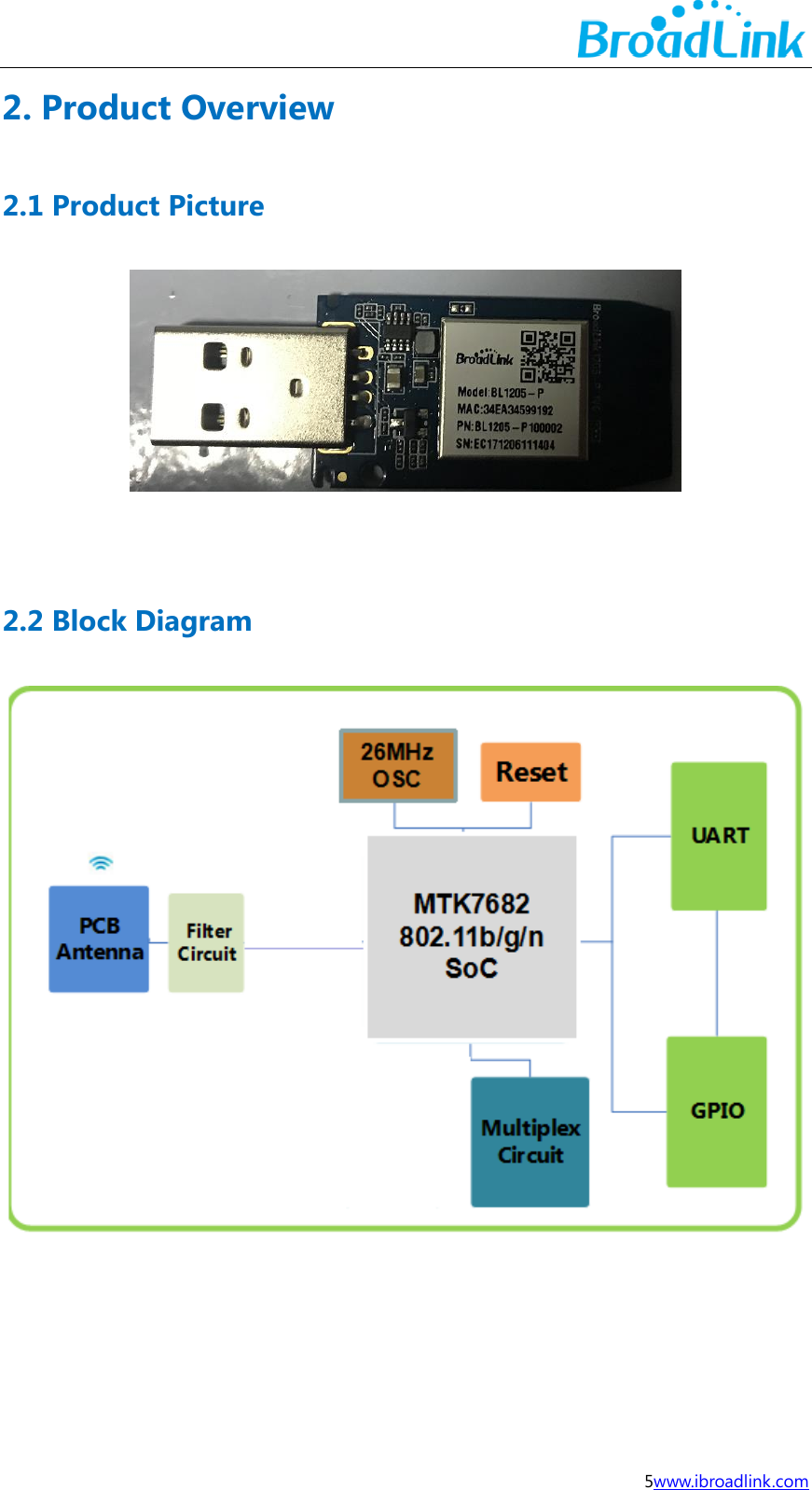
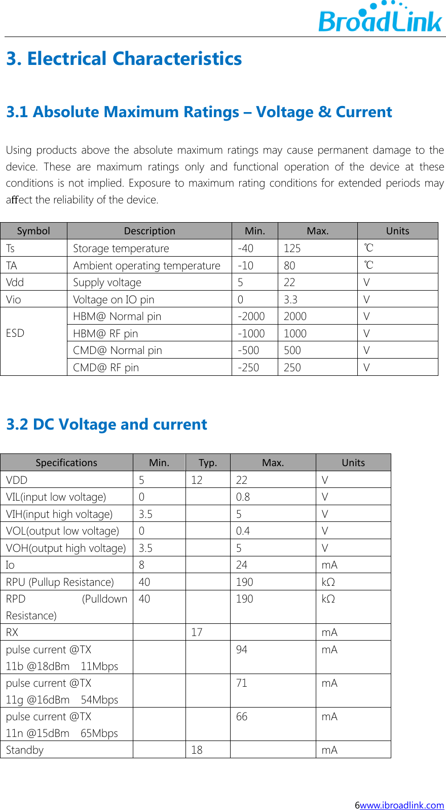
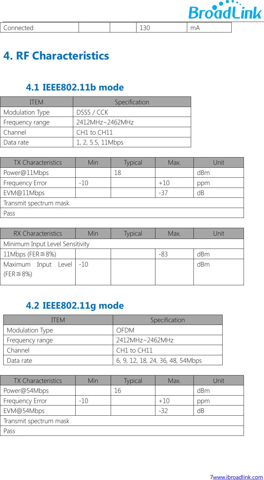
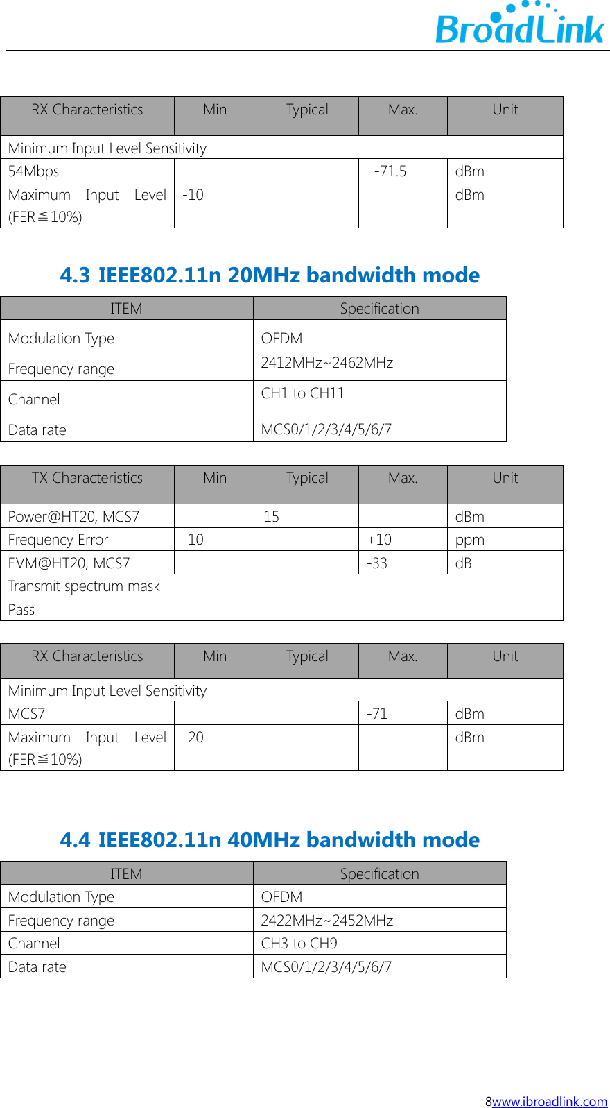
![16www.ibroadlink.com TX Transmitter IP Internet Protocol UART Universal Asynchronous Receiver/Transmitter UDP User Datagram Protocol UFL a miniature coaxial RF connector for high-frequency signals manufactured by Hirose Electric Group VSWR Voltage Standing Wave Ratio WEP Wired Equivalent Privacy WEPA Welded Electronic Packaging Association WEP64 64 bit Wired Equivalent Privacy WEP128 128 bit Wired Equivalent Privacy WPA2 Wi-Fi Protected Access 2 XTAL External Crystal Oscillator QAM Quadrature Amplitude Modulation 802.11 b/g/n The IEEE 802.11 b/g/n Appendix B Reference paper(Quentin respible) [1] IEEE 802.11b/g/n- published IEEE 802.11-2007wireless networking standard and published IEEE 802.11-2012 standard for Information technology - Clause 19 of the publishedIEEE 802.11-2007 standard, and Clause 19 of the published IEEE 802.11-2012 standard.](https://usermanual.wiki/Hangzhou-Gubei-Electronics-Technology/BL1205-P/User-Guide-3730033-Page-17.png)