Hangzhou Gubei Electronics Technology BL1205-P WiFi Module User Manual users manual
Hangzhou Gubei Electronics Technology Co.,Ltd WiFi Module users manual
users manual

BiTrend™ EssentialSeriesWi-Fi Module
Datasheet
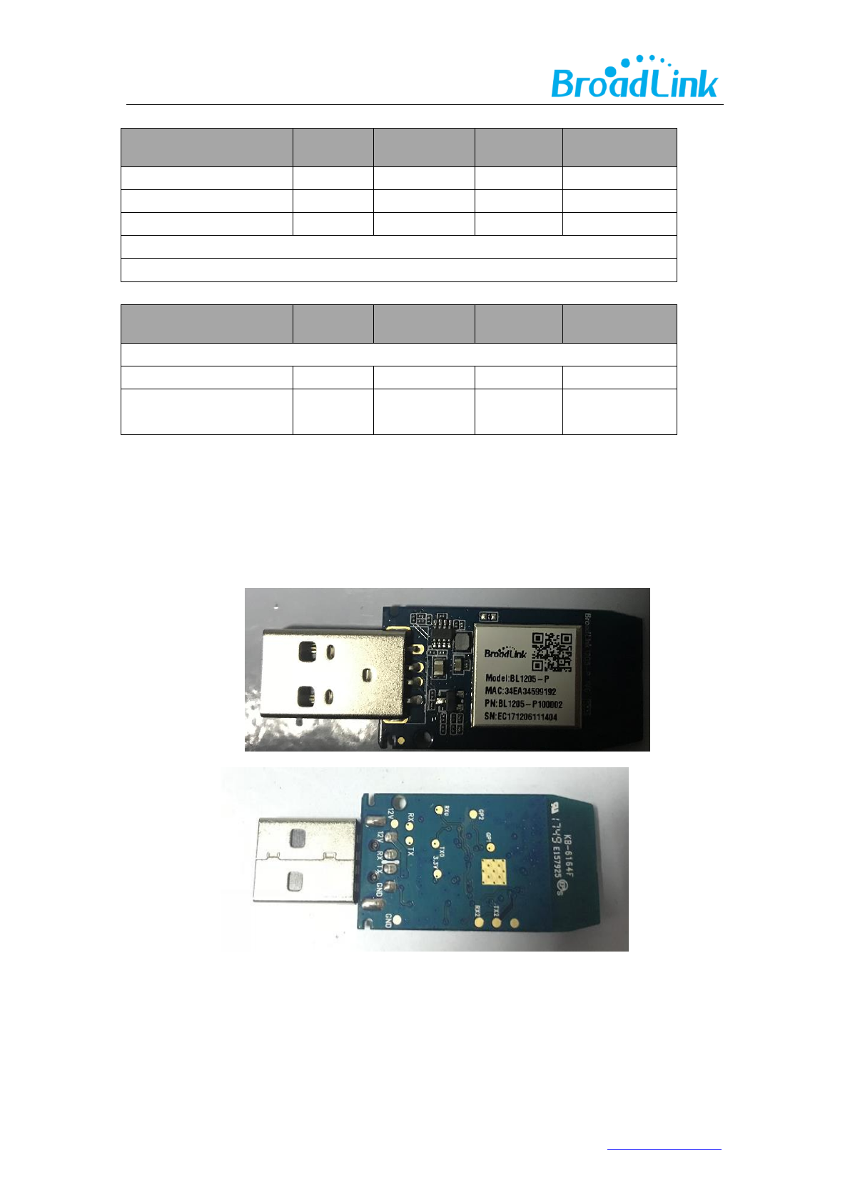
BL1205-P
1www.ibroadlink.com
Hangzhou Gubei Electronics Technology Co., Ltd.
Copyright Information
The information contained in this document is the proprietary information of Hangzhou Gubei
Electronics Technology Co., Ltd. (hereinafter referred as BroadLink). Further, no portion of this
document may be altered or edited in any form or by any meanswithout the prior written
consent of BroadLink, the copyrightholder.
Further BroadLink reserves the right to make modifications, additions anddeletions to this
document due to typographical errors, inaccurate information, orimprovements to products
mentioned in the document at any time and without notice. Such changes will, nevertheless be
incorporated into new editions of this document or published as errata sheet.
Version History
1.0
11/6/2017
Preliminary version
1.1
11/29/2017
Corrected some parameters

2www.ibroadlink.com
Table of Contents
1. Introduction ................................................................................................................................. 3
1.1 Overview ............................................................................................................................ 3
1.2 Applications ....................................................................................................................... 4
1.3 Key Features ...................................................................................................................... 4
2. Product Overview ....................................................................................................................... 5
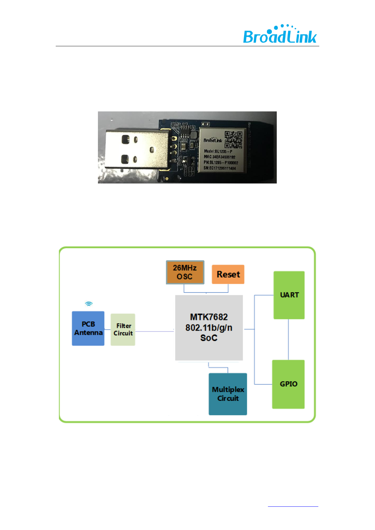
2.1 Product Picture ................................................................................................................. 5
2.2 Block Diagram ................................................................................................................... 5
3. Electrical Characteristics ............................................................................................................. 6
3.1 Absolute Maximum Ratings – Voltage & Current ........................................................ 6
3.2 DC Voltage and current ................................................................................................... 6
4. RF Characteristics ........................................................................................................................ 7
5.Mechanical Characteristics ......................................................................................................... 9
6. Module Interfaces ..................................................................................................................... 10
6.1 PIN Layout ....................................................................................................................... 10
6.2 PIN Definitions ................................................................................................................ 10
7. Reference Design ...................................................................................................................... 11
Power supply requirements ............................................................................................ 11
8. AntennaCharacteristics ............................................................................................................ 12
8.1 Antenna Selection .......................................................................................................... 12
8.2 Minimizing Radio Interference .................................................................................... 13
9. removable sticker ........................................................................................................................ 14
Appendix A Glossary(Quentin respible) ............................................................................... 14
Appendix B Reference paper(Quentin respible) .................................................................. 16
Contact Us ..................................................................................................................................... 17

3www.ibroadlink.com
1. Introduction
1.1 Overview
BiTrend™ Essentialis the industrial leading 2.4Ghz 802.11 b/g/n embedded Wi-Fi module which
delivers unmatched performance and codeless development in a compact package, providing
a quick, easy and cost effective way for developers and manufacturers to add Wi-Fi connectivity
for home automation, lighting control, energy efficiency and other IOT applications.
BiTrend™ Essential family combines a 2.4Ghz 802.11 b/g/n radio transceiver with a 32-bit
microprocessor and embedded with MAC, baseband processing and optimized Wi-Fi network
stack. It is an ideal solution for developers and manufacturers with limited RF and embedded
programming expertise as it significantly reduces RF design time and removes the burden of
testing and certification.
Benefitted from BroadLink’s turn-key solution, BiTrend™ Essential is an ideal solution for
developers with limited Wi-Fi or RF expertise or for those seeking faster time to market. It
reduces RF design time and removes the burden of testing and certification. BiTrend™ Essential
is fully compliant with IEEE 802.11 b/g/n standard and certified with CE, FCC and RoHS.
BiTrend™ Essential is a highly integrated Wi-Fi SoC(system on Chip) single chip, which
supportsIEEE802.11b/g/n single stream, providing GPIO for intelligent control, and UART
interfaces for device communication.
BiTrend™ Essential has 8Mbits flash and integrates power amplifier, low noise amplifier, and RF
switch to reduce the module size and RF design capability required. And also integrate power
manage unit for single 3.3V power source for cost effective design.
BiTrend™ Essential embedded 32-bit RISC MCU for 802.11b/g/n drivers, supplicant, TCP/IP
protocol stack, and networking applications, can be operated in station mode and softAP mode.
The BL1205-P is an ideal solution for embedded device to enable networking service with
minimized design effort.
RF
receiver
RF
transmitter
Baseband
MAC /
Packet
buffer /
security
engine
UART
System
control
RF_IN
RF_OUTP
RF_OUTN
UART
GPIO/LED
4www.ibroadlink.com
1.2 Applications
Smart home appliances
Remote Control
Medical/Health Care
Network consumer devices
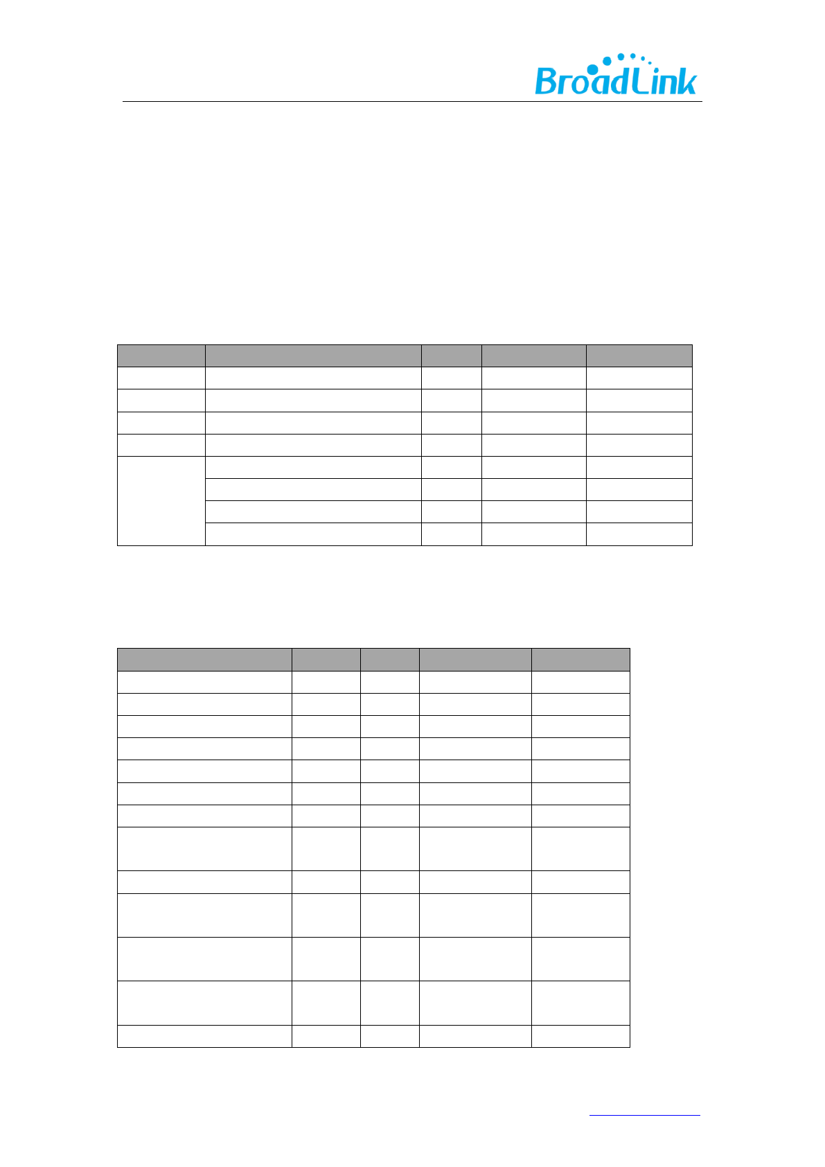
1.3 Key Features
a. Support IEEE802.11b/g/n
Frequency range
2.412 GHz- 2.462 GHz
Wireless standard
IEEE 802.11 b/g/n
Radio power
802.11b:18dBm
802.11g:16dBm
802.11n:15dBm
Antenna
On board: PCB antenna
External: Not supported
Receiving sensitivity
802.11b<-83dBm@11Mbps
802.11g<-72dBm@54Mbps
802.11n<-71dBm@MCS7
Supported stacks
IPv4, TCP/UDP/FTP/HTTP/HTTPS/TLS/mDNS
Data rate (max)
11M@802.11b, 54M@802.11g, MCS7@802.11n
Security support
Encryption standard:
Open/WEP-Open/WPA/WPA2
Encryption algorithm: WEP64/WEP128/TKIP/AES
Wi-Fi Modes
STA/AP/STA+AP/WIFI Direct
b. Support UART\PWM\ADC\GPIO\I2C
c. Support STA\AP\AP+STA
d. Patent Smart Config™ technology
e. Support TLS\SSL\mDNS
f. PCB printed antenna
Antenna type
PCB printed ANT
g. Power source: 12V
Dimension Dimensions: L 35.5(-0.1~+0.35)mm * W 19.5(-0.1~+0.35)mm * H
(5.3±10%)mm (USB port)
h. ESD: 2KV
6www.ibroadlink.com
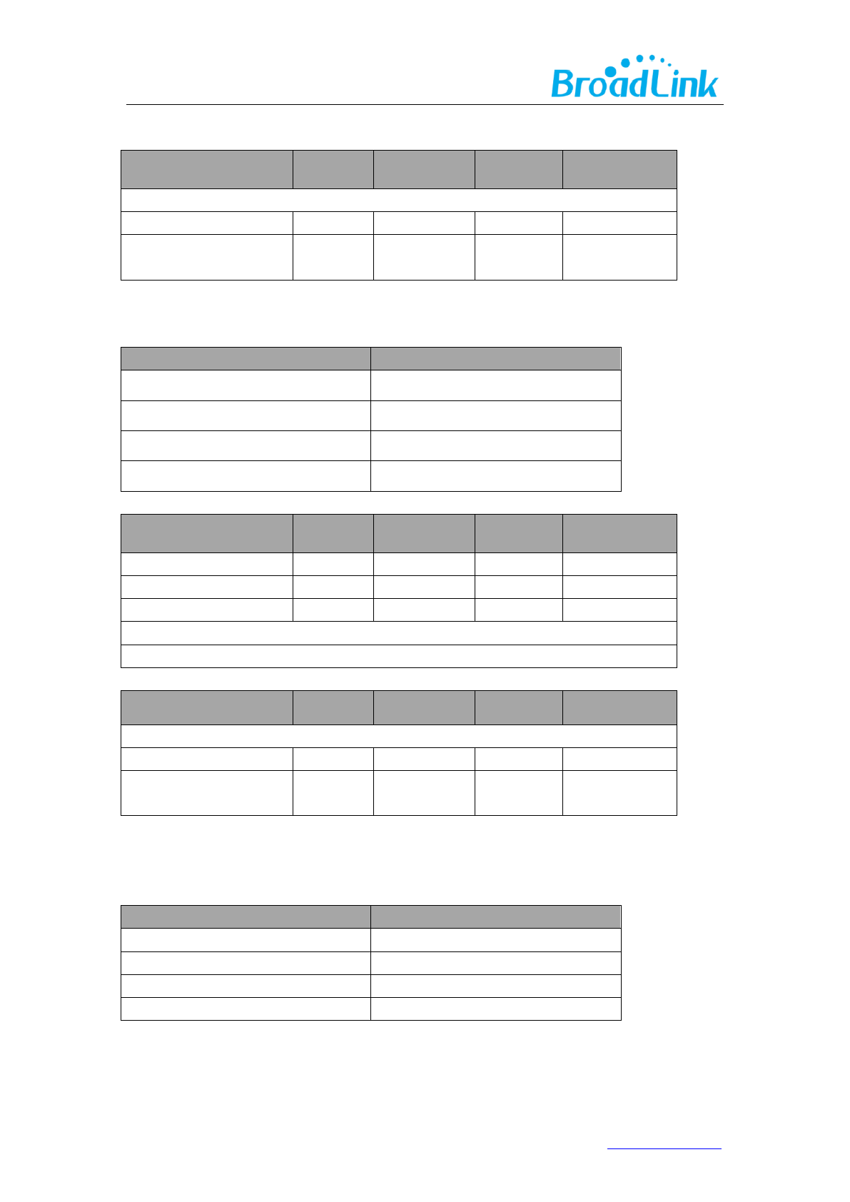
3. Electrical Characteristics
3.1 Absolute Maximum Ratings – Voltage & Current
Using products above the absolute maximum ratings may cause permanent damage to the
device. These are maximum ratings only and functional operation of the device at these
conditions is not implied. Exposure to maximum rating conditions for extended periods may
affect the reliability of the device.
Symbol
Description
Min.
Max.
Units
Ts
Storage temperature
-40
125
℃
TA
Ambient operating temperature
-10
80
℃
Vdd
Supply voltage
5
22
V
Vio
Voltage on IO pin
0
3.3
V
ESD
HBM@ Normal pin
-2000
2000
V
HBM@ RF pin
-1000
1000
V
CMD@ Normal pin
-500
500
V
CMD@ RF pin
-250
250
V
3.2 DC Voltage and current
Specifications
Min.
Typ.
Max.
Units
VDD
5
12
22
V
VIL(input low voltage)
0
0.8
V
VIH(input high voltage)
3.5
5
V
VOL(output low voltage)
0
0.4
V
VOH(output high voltage)
3.5
5
V
Io
8
24
mA
RPU (Pullup Resistance)
40
190
kΩ
RPD (Pulldown
Resistance)
40
190
kΩ
RX
17
mA
pulse current @TX
11b @18dBm 11Mbps
94
mA
pulse current @TX
11g @16dBm 54Mbps
71
mA
pulse current @TX
11n @15dBm 65Mbps
66
mA
Standby
18
mA

7www.ibroadlink.com
Connected
130
mA
4. RF Characteristics
4.1 IEEE802.11b mode
ITEM
Specification
Modulation Type
DSSS / CCK
Frequency range
2412MHz~2462MHz
Channel
CH1 to CH11
Data rate
1, 2, 5.5, 11Mbps
TX Characteristics
Min
Typical
Max.
Unit
Power@11Mbps
18
dBm
Frequency Error
-10
+10
ppm
EVM@11Mbps
-37
dB
Transmit spectrum mask
Pass
RX Characteristics
Min
Typical
Max.
Unit
Minimum Input Level Sensitivity
11Mbps (FER≦8%)
-83
dBm
Maximum Input Level
(FER≦8%)
-10
dBm
4.2 IEEE802.11g mode
ITEM
Specification
Modulation Type
OFDM
Frequency range
2412MHz~2462MHz
Channel
CH1 to CH11
Data rate
6, 9, 12, 18, 24, 36, 48, 54Mbps
TX Characteristics
Min
Typical
Max.
Unit
Power@54Mbps
16
dBm
Frequency Error
-10
+10
ppm
EVM@54Mbps
-32
dB
Transmit spectrum mask
Pass
8www.ibroadlink.com
RX Characteristics
Min
Typical
Max.
Unit
Minimum Input Level Sensitivity
54Mbps
-71.5
dBm
Maximum Input Level
(FER≦10%)
-10
dBm
4.3 IEEE802.11n 20MHz bandwidth mode
ITEM
Specification
Modulation Type
OFDM
Frequency range
2412MHz~2462MHz
Channel
CH1 to CH11
Data rate
MCS0/1/2/3/4/5/6/7
TX Characteristics
Min
Typical
Max.
Unit
Power@HT20, MCS7
15
dBm
Frequency Error
-10
+10
ppm
EVM@HT20, MCS7
-33
dB
Transmit spectrum mask
Pass
RX Characteristics
Min
Typical
Max.
Unit
Minimum Input Level Sensitivity
MCS7
-71
dBm
Maximum Input Level
(FER≦10%)
-20
dBm
4.4 IEEE802.11n 40MHz bandwidth mode
ITEM
Specification
Modulation Type
OFDM
Frequency range
2422MHz~2452MHz
Channel
CH3 to CH9
Data rate
MCS0/1/2/3/4/5/6/7
9www.ibroadlink.com
TX Characteristics
Min
Typical
Max.
Unit
Power@HT40, MCS7
14.5
dBm
Frequency Error
-10
+10
ppm
EVM@HT40, MCS7
-33
dB
Transmit spectrum mask
Pass
RX Characteristics
Min
Typical
Max.
Unit
Minimum Input Level Sensitivity
MCS7
-69
dBm
Maximum Input Level
(FER≦10%)
-20
dBm
5.Mechanical Characteristics
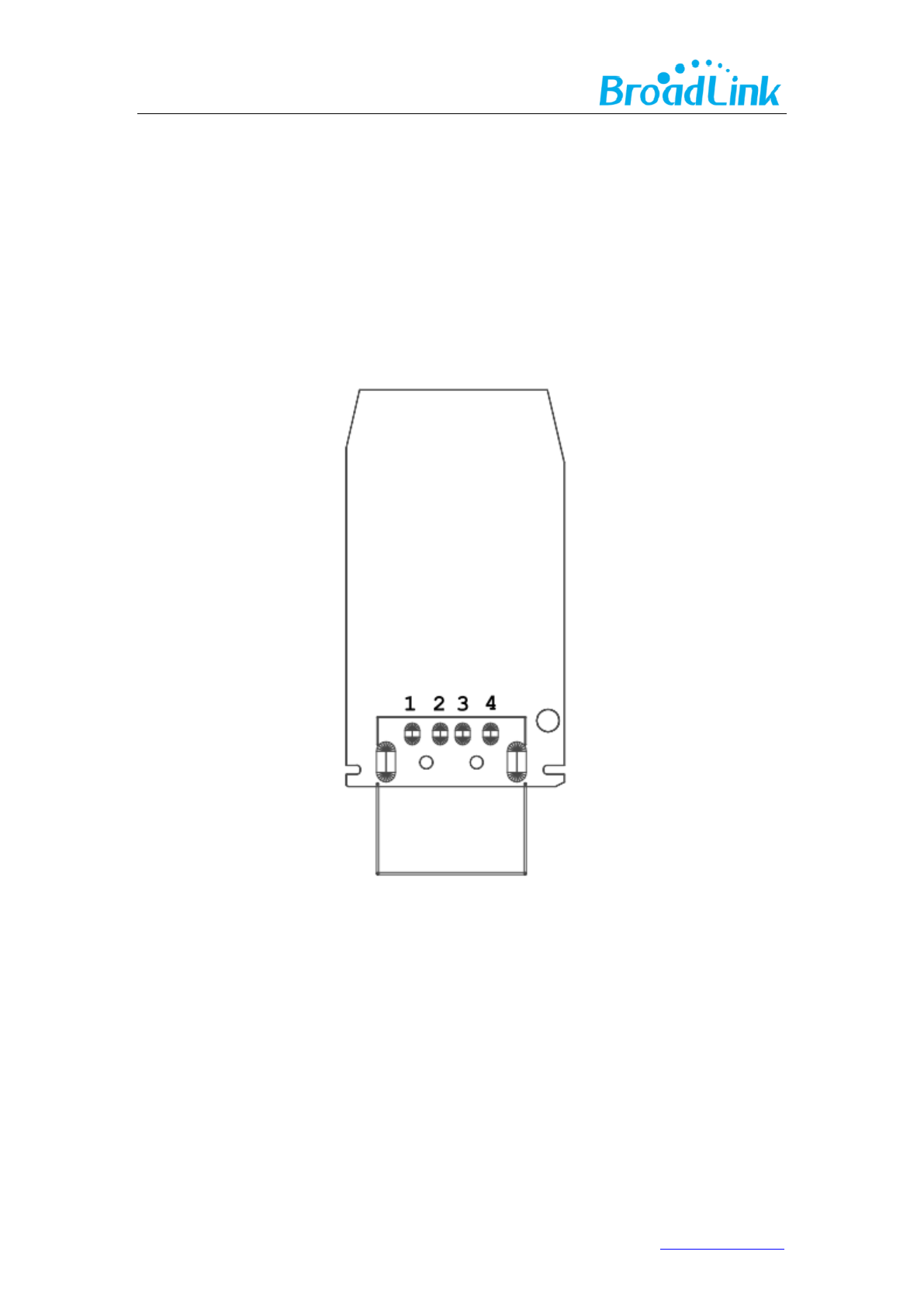

11www.ibroadlink.com
pin
网络
描述
类型
1
GND
GND
POWER
2
TX
UART0_TX 5V
O
3
RX
UART0_RX 5V
I
4
VDD
12V INPUT
POWER
7. Reference Design
Power supply requirements
It is recommended to supply the module with power higher than 150mA (12V) to ensure
enough power supply to the module and avoid power down during data transmission.
13www.ibroadlink.com
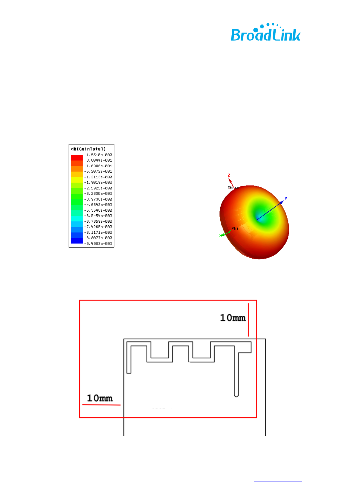
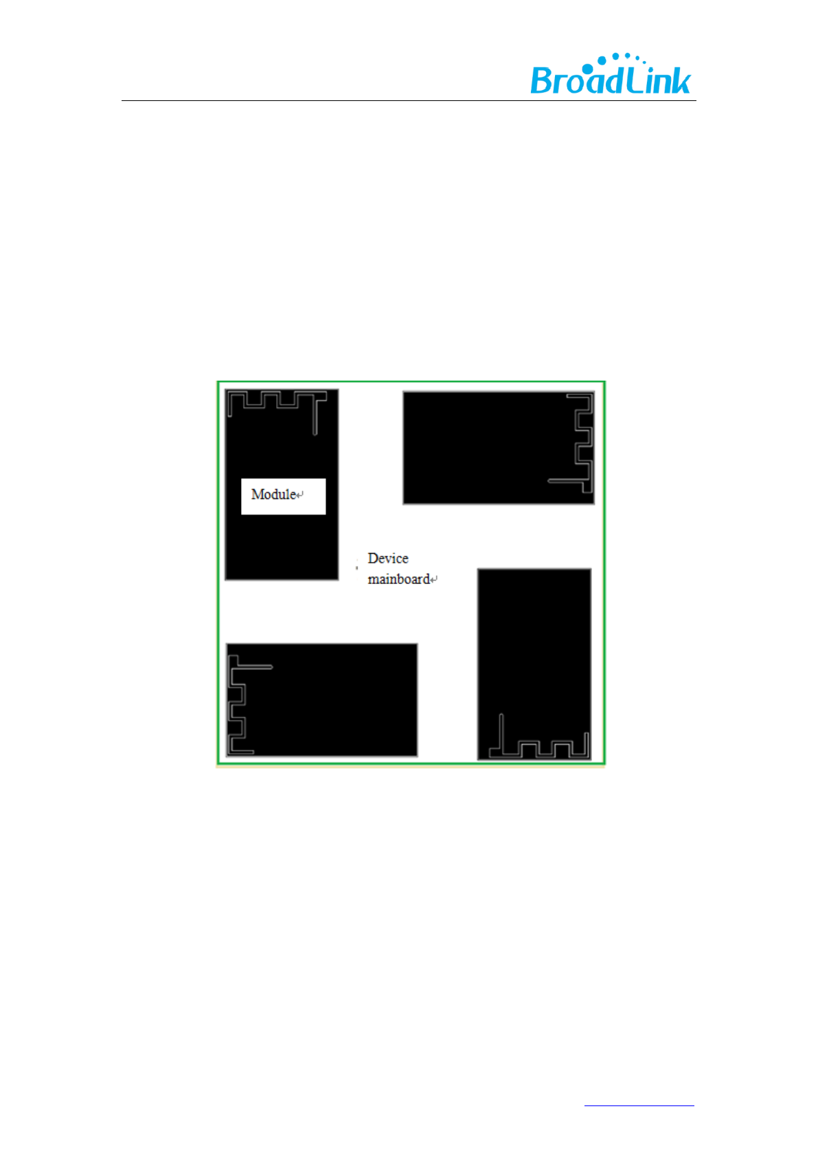
8.2 Minimizing Radio Interference
The following precautions should be considered during designing when using PCB antenna:
1. Do not place any electrical components in antenna area on main board and it’s better to
leave this area blank on PCB.
2. It is recommended to not place any electrical components within 10mm range of module
antenna and not design any circuit or bond copper on main board under this area.
3. Do not use the module inside any metal case or containers with metal painting.
Keep the antenna of wifi module next to the edge of main board during design of PCB to
ensure better performance of antenna.

14www.ibroadlink.com
9. Removable sticker
This device complies with Part 15 of the FCC Rules. Operation is subject to the following two conditions:
(1) This device may not cause harmful interference, and
(2) This device must accept any interference received, including interference that may cause undesired
operation
Appendix A Glossary(Quentin respible)
ADC
Analog-to -Digital Converter
AES
Advanced Encryption Standard
ANT
Antenna
AP
Wireless Access Point
BPSK
Binary Phase Shift Keying
DBPSK
Differential binary phase shift keying
DC
Direct Current
CC
K
Complementary Code Keying

15www.ibroadlink.com
CDM
Charge Device Model
DHCP
Dynamic Host Configuration Protocol
CMOS
Complementary Metal Oxide Semiconductor
DNS
Determination of non-significance
DQPSK
Differential quadrature phase shift keying
DSSS
Demand assigned signaling and switching subsystem
DTIM
Digital Transmission Interface Module
EMSP
Enhanced Modular Signal Processor
ESD
Electrostatic Discharge
EVM
Error Vector Magnitude
FCC
Federal Communications Commission
FER
Floating Error
GND
Ground
GPIO
General Purpose Input/Output
HBM
Human body model
IEEE
Institute of Electrical and Electrionics Engineers
IO
Input/Output
IOT
Individual operation test
IPv4
Internet Protocol version 4
LED
Light-emitting diode
LVTTL
Low Voltage Transistor Transistor Logic
MAC
Medium Access Control layer
MCS
Modulation and coding scheme
MCU
Microcontroller Unit
MIMO
Multiple-Input Multiple-Output
MSL
Multilayer Switching Protocol
NC
Numerical Control
NRST
Negative Reset
OF
DM
Orthogonal Frequency Division Multiplexing
OSC
Oscillator
PCB
Printed Circuit Board
PIFA
Planar inverted F antenna
QPSK
Quadrature Phase Shift Keyin
RC
Resistance- capacitance
RF
Radio Frequency
RISC
Reduced Instruction Set Computer
RoHS
Restriction of Hazardous Substances
RX
Receiver
SDIO
Serial Digital Input/Output
SoC
System on Chip
SPDT
Single-Pole Double-Throw
SPI
Serial Peripheral Interface
STA
Spanning Tree Algorithm
TCP
Transfer Control Protocol
TKIP
Temporal Key Integrity Protocol

16www.ibroadlink.com
TX
Transmitter
IP
Internet Protocol
UART
Universal Asynchronous Receiver/Transmitter
UDP
User Datagram Protocol
UFL
a miniature coaxial RF connector for high-frequency signals
manufactured by Hirose Electric Group
VSWR
Voltage Standing Wave Ratio
WEP
Wired Equivalent Privacy
WEPA
Welded Electronic Packaging Association
WEP64
64 bit Wired Equivalent Privacy
WEP128
128 bit Wired Equivalent Privacy
WPA2
Wi-Fi Protected Access 2
XTAL
External Crystal Oscillator
QAM
Quadrature Amplitude Modulation
802.11 b/g/n
The IEEE 802.11 b/g/n
Appendix B Reference paper(Quentin respible)
[1] IEEE 802.11b/g/n- published IEEE 802.11-2007wireless networking standard and
published IEEE 802.11-2012 standard for Information technology - Clause 19 of the
publishedIEEE 802.11-2007 standard, and Clause 19 of the published IEEE
802.11-2012 standard.

17www.ibroadlink.com
Contact Us
Hangzhou Gubei Electronics Technology Co., Ltd.
Room 106, Building 1, No. 611 Jianghong Road, Binjiang, Hangzhou, Zhejiang, P.R.China
T: +86-571-85159281 F: +86-571-86631817
E: intl@broadlink.com.cn W: www.ibroadlink.com.cn
This device complies with Part 15 of the FCC Rules / Industry Canada licence-exempt
RSS standard(s). Operation is subject to the following two conditions: (1) this device
may not cause harmful interference, and (2) this device must accept any interference
received, including interference that may cause undesired operation.
Le présent appareil est conforme aux CNR d'Industrie Canada applicables aux
appareils radio exempts de licence. L'exploitation est autorisée aux deux conditions
suivantes : (1) l'appareil ne doit pas produire de brouillage, et (2) l'utilisateur de
l'appareil doit accepter tout brouillage radioélectrique subi, même si le brouillage est
susceptible d'en compromettre le fonctionnement.

18www.ibroadlink.com
Changes or modifications not expressly approved by the party
responsible for compliance could void the user's authority to operate the
equipment.
This equipment has been tested and found to comply with the limits for
a Class B digital device, pursuant to part 15 of the FCC Rules. These
limits are designed to provide reasonable protection against harmful
interference in a residential installation. This equipment generates
uses and can radiate radio frequency energy and, if not installed and
used in accordance with the instructions, may cause harmful interference
to radio communications. However, there is no guarantee that interference
will not occur in a particular installation. If this equipment does cause
harmful interference to radio or television reception, which can be
determined by turning the equipment off and on, the user is encouraged
to try to correct the interference by one or more of the following
measures:
—Reorient or relocate the receiving antenna.
—Increase the separation between the equipment and receiver.
—Connect the equipment into an outlet on a circuit different from that
to which the receiver is connected.
—Consult the dealer or an experienced radio/TV technician for help.
MPE Requirements
To satisfy FCC / IC RF exposure requirements, a separation distance of 20 cm or more should be
maintained between the antenna of this device and persons during device operation.
To ensure compliance, operations at closer than this distance is not recommended.
Les antennes installées doivent être situées de facon à ce que la population ne puisse
y être exposée à une distance de moin de 20 cm. Installer les antennes de facon à ce
que le personnel ne puisse approcher à 20 cm ou moins de la position centrale de l’
antenne.
La FCC des éltats-unis stipule que cet appareil doit être en tout temps éloigné d’au
moins 20 cm des personnes pendant son functionnement.
Region Selection
Limited by local law regulations, version for North America does not have region selection option.
Information for the OEM Integrators
This device is intended for OEM integrators only. Please see the full grant of
equipment document for restrictions.
Label Information to the End User by the OEM or Integrators
