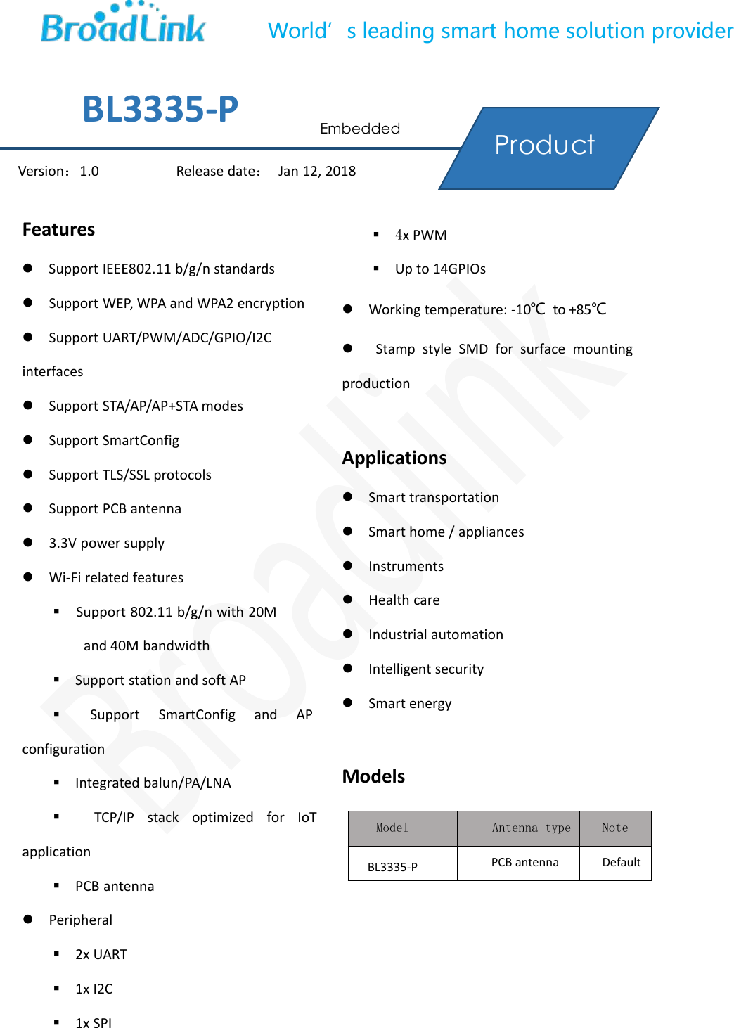
Hangzhou Gubei Electronics Technology BL3335-P WiFi Module User Manual
Hangzhou Gubei Electronics Technology Co.,Ltd WiFi Module
UserManual.wiki
>
Hangzhou Gubei Electronics Technology
>
BL3335 P User Manual
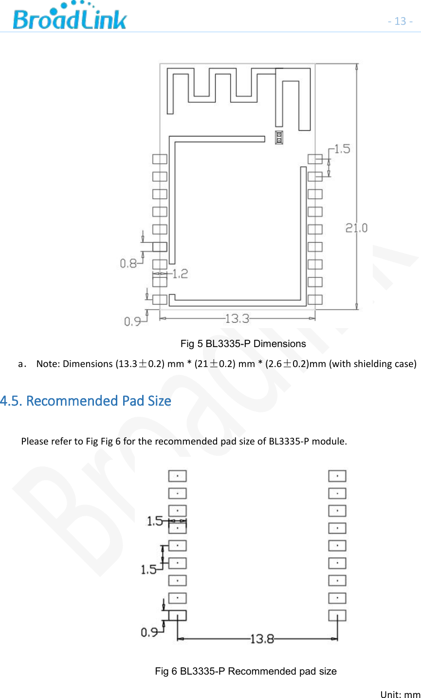
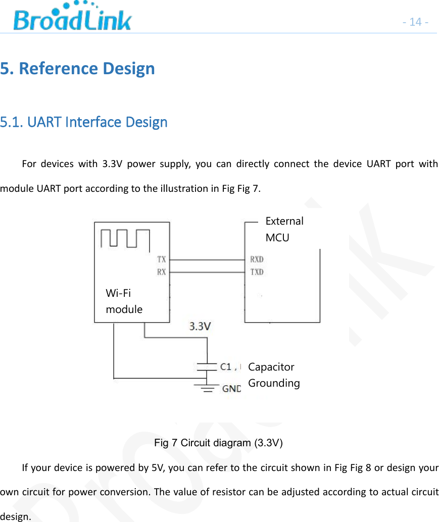
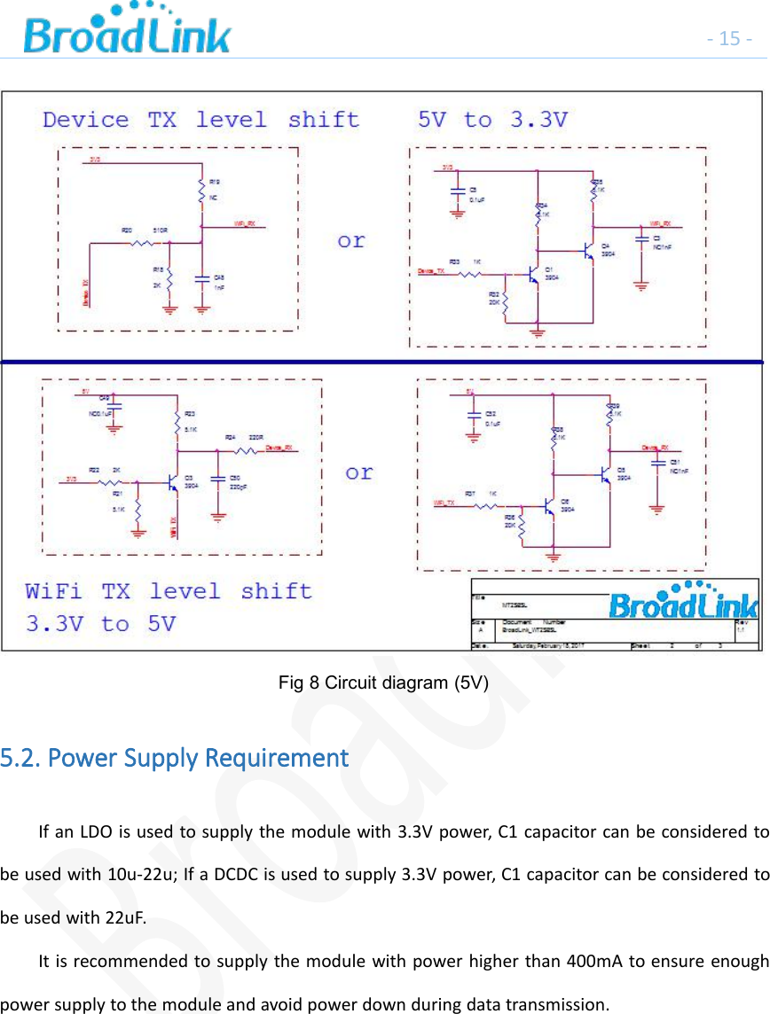
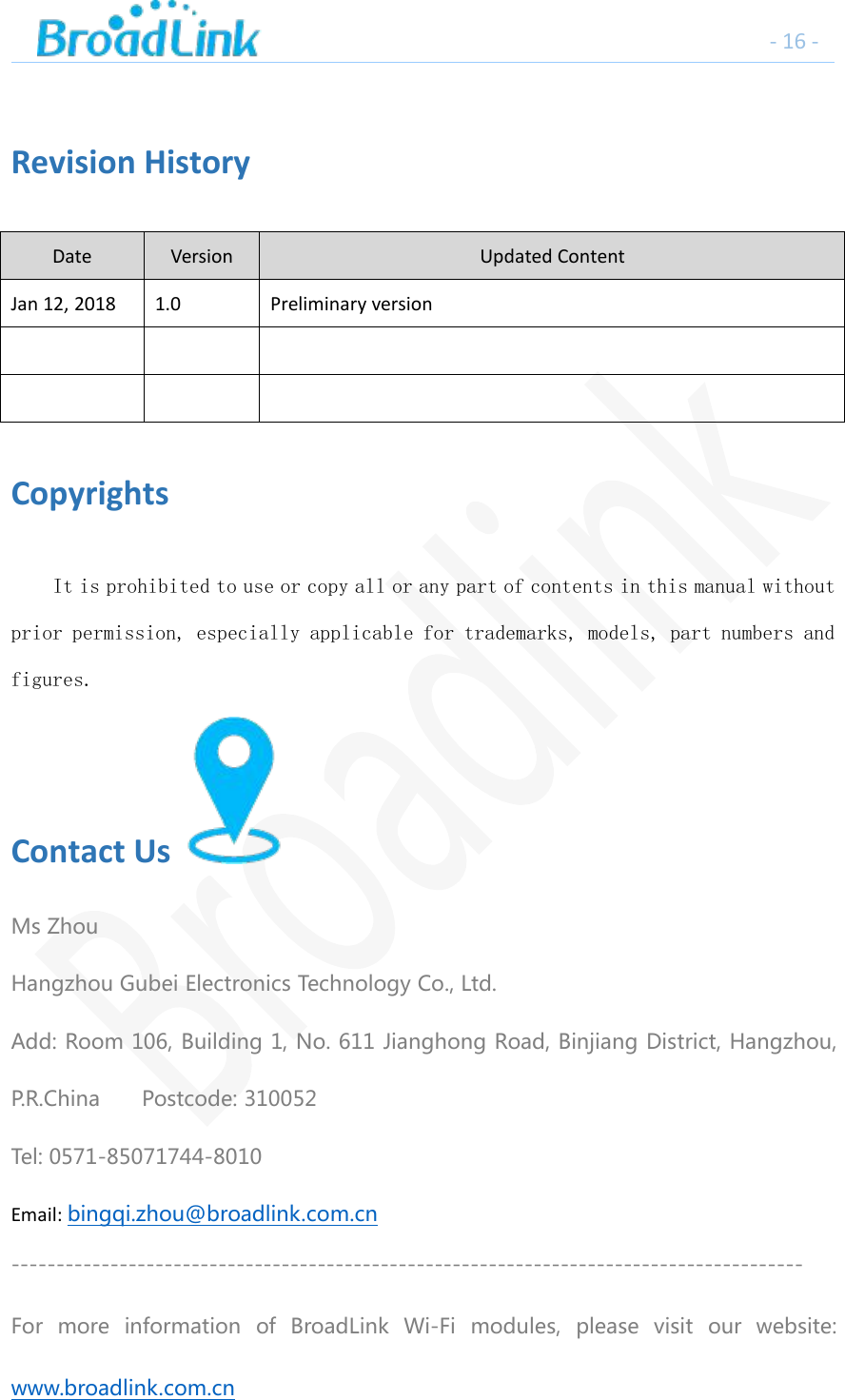
User Manual
Navigation menu
Upload a User Manual
Namespaces
Wiki Guide
HTML
PDF
Info
Views
User Manual
Discussion / Help
Navigation