Hangzhou Hikvision Digital Technology 25IPC Network Camera User Manual 3
Hangzhou Hikvision Digital Technology Co., Ltd. Network Camera 3
UserManual.wiki
>
Hangzhou Hikvision Digital Technology
>
25IPC User Manual
>
User Manual 3
Contents
1.
User Manual 3
2.
User Manual i
3.
User Manual ii
User Manual 3
Navigation menu
Upload a User Manual
Namespaces
Wiki Guide
HTML
PDF
Info
Views
User Manual
Discussion / Help
Navigation
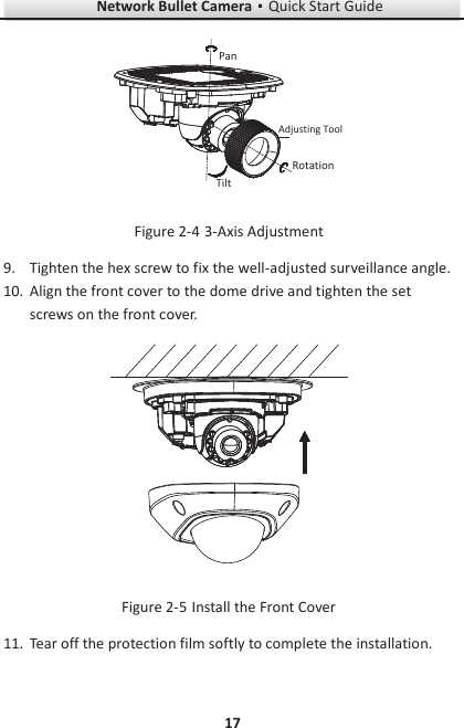
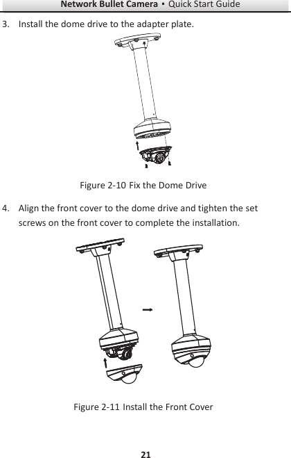
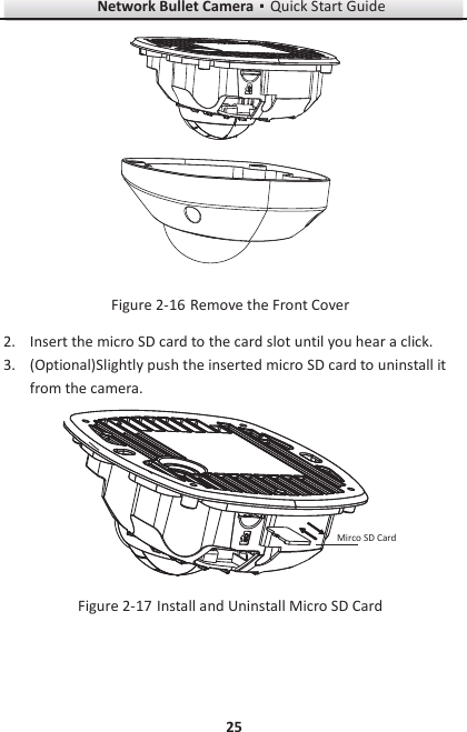
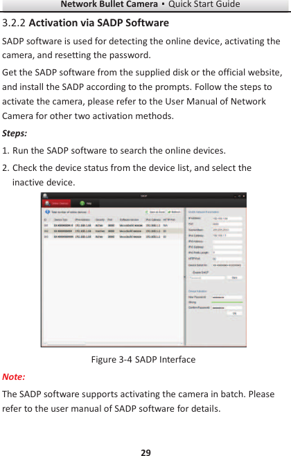
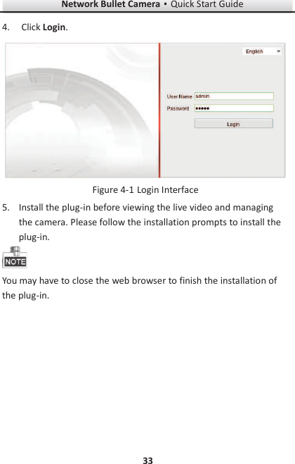
![Network Bullet CameragQuick Start Guide 16 3. Hammer the plugs of the expansion screws to the ceiling. 4. Connect the power cable, network cable, and the audio/alarm cables. 5. Fix the camera body to the ceiling with the supplied expansion screws. Fix the Adapter Plate Figure 2-36. View the image via the web browser. 7. Slightly loosen the hex screw beside the WPS/RESET button to adjust the surveillance angle. 8. Use the supplied adjusting tool to adjust the pan [ᱡ30ᲄ], tilt [0~80ᲄ], and rotation direction [0~360ᲄ].](https://usermanual.wiki/Hangzhou-Hikvision-Digital-Technology/25IPC.User-Manual-3/User-Guide-2698423-Page-16.png)