Hangzhou Hikvision Digital Technology D0211504 Dual-tech Detector User Manual RINS1691 3 KX15DTAM A3 EXPORT 040716
Hangzhou Hikvision Digital Technology Co., Ltd. Dual-tech Detector RINS1691 3 KX15DTAM A3 EXPORT 040716
User Manual
For electrical products sold within the European Community. At the end of the electrical
products life, it should not be disposed of with household waste. Please recycle where
country. This product operates in a European non-harmonised frequency band. Hereby
at www.pyronix.com/product-compliance.php
Commercial and Light Industrial Environment.
DS-PD2-D15AME
15m DualͲƚĞĐŚ Detector
>1m
ч1m
3K
15K
12K
8K2
6K8
5K6
4K7
2K2
1K
6K8
5K6
4K7
2K2
1K
5K6
4K7
2K2
1K
3K
15K
12K
8K2
6K8
5K6
4K7
2K2
1K
6K8
5K6
4K7
2K2
1K
5K6
4K7
2K2
1K
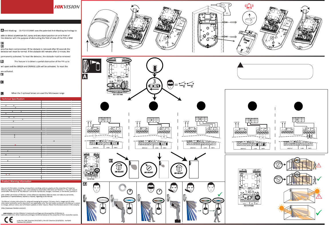
detect when both PIR and Microwave technologies are Masked. The detector is
sensors.
The Mask is adjustable between 0 to 1M.
/ĨƚŚĞDĂƐŬŝŶŐĂƌĞĂŝƐĞŶƚĞƌĞĚƚŚĞůƵĞ>ƐƚĂƌƚƐŇĂƐŚŝŶŐƚŽƐŚŽǁƚŚĂƚƚŚĞ
MASK and ALARM relay will open and the Green and Orange LEDs will be
and a walk test must be done.
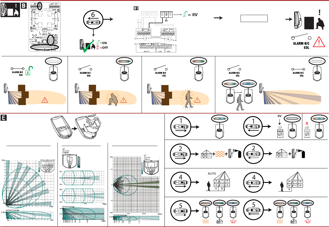
Blocking:
15m when the panel is disarmed. When blocking is detected the alarm relay
blocking, the DS-PD2-D15AME must be walk tested so that the PIR and MW sensors
Blocking Enabled/Disabled: To enable the feature, switch 6 must be OFF
and the RI input should be connected to an output on the control panel which
gives 0V when DISARMED and removes 0V when ARMED.
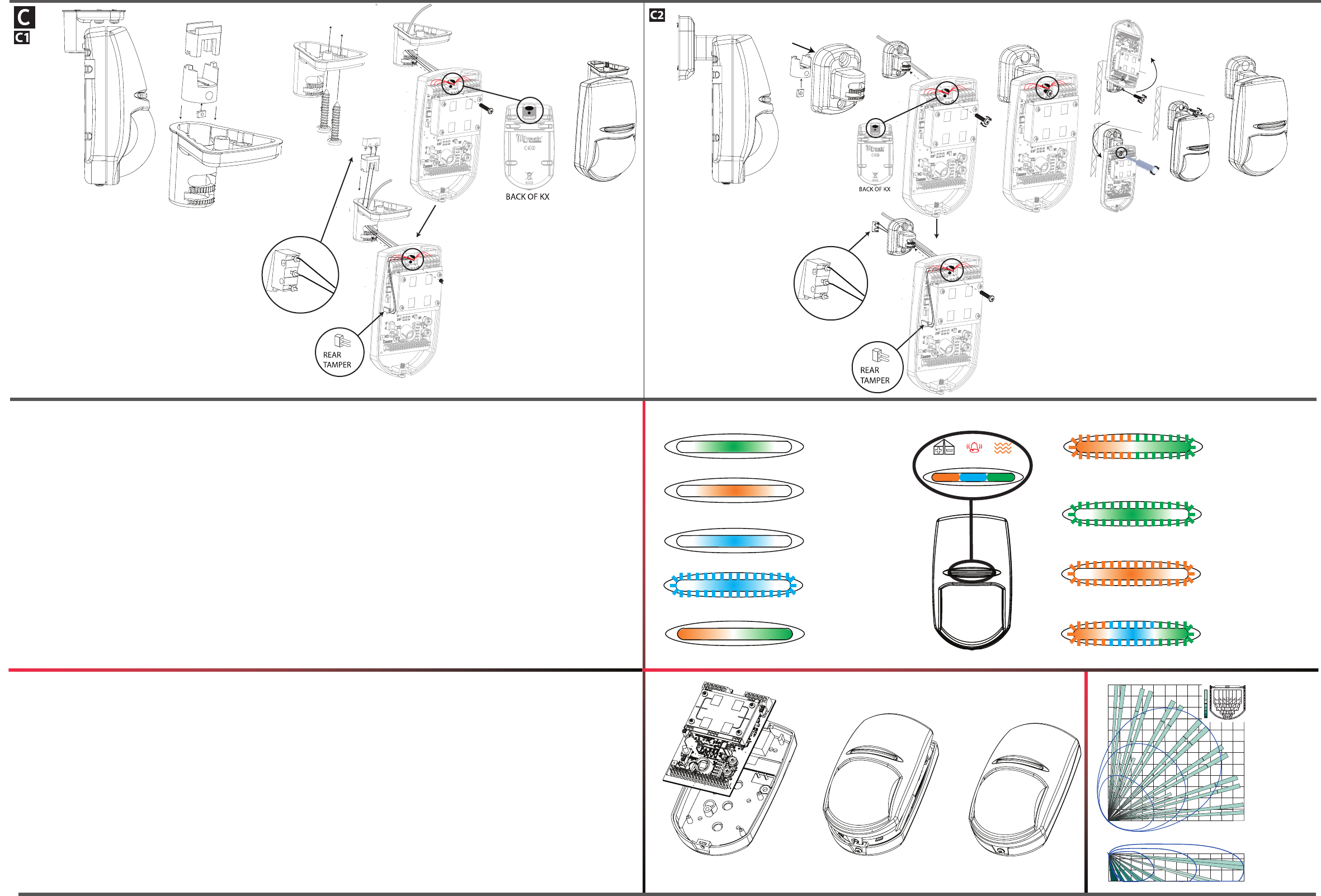
DS-PD2-D15AME is supplied with the following:
BRACKETW (Wall Bracket), BRACKETC (Ceiling Bracket) and TAMPER
(Back tamper)
NOTE:
remains at 15m.
3K
15K
12K
8K2
6K8
5K6
4K7
2K2
1K
6K8
5K6
4K7
2K2
1K
5K6
4K7
2K2
1K
3K
15K
12K
8K2
6K8
5K6
4K7
2K2
1K
6K8
5K6
4K7
2K2
1K
5K6
4K7
2K2
1K
START
3EOL
A A T T
EOL INPUT 1 COM
Max: 1M
1M
MAX
DEOL
A A T T
EOL INPUT 1 COM
N/C HIK GENERAL
A A T T
EOL INPUT 1 COM
MASK/ALARM EOL
LINK
30% Mask
30%
OFF
3K
15K
12K
8K2
6K8
5K6
4K7
2K2
1K
6K8
5K6
4K7
2K2
1K
5K6
4K7
2K2
1K
3K
15K
12K
8K2
6K8
5K6
4K7
2K2
1K
6K8
5K6
4K7
2K2
1K
5K6
4K7
2K2
1K
3K
15K
12K
8K2
6K8
5K6
4K7
2K2
1K
6K8
5K6
4K7
2K2
1K
5K6
4K7
2K2
1K
3K
15K
12K
8K2
6K8
5K6
4K7
2K2
1K
6K8
5K6
4K7
2K2
1K
5K6
4K7
2K2
1K
3K
15K
12K
8K2
6K8
5K6
4K7
2K2
1K
6K8
5K6
4K7
2K2
1K
5K6
4K7
2K2
1K
User Manual
COPYRIGHT ©2018 Hangzhou Hikvision Digital Technology Co., Ltd.
ALL RIGHTS RESERVED.
or implied, regarding to the Manual.
About this Manual
This manual is applicable to video security control panel.
Please use this user manual under the guidance of professionals.
Trademarks Acknowledgement
Diagram references
This product and - if applicable - the supplied accessories too are marked with "CE"
and comply therefore with the applicable harmonized European standards listed
COPYRIGHT ©2018 Hangzhou Hikvision Digital Technology Co., Ltd.
ALL RIGHTS RESERVED.
wholly, by any means, without the
About this Manual
This manual is applicable to detector.
website
Please use this user manual under the guidance of professionals.
Trademarks Acknowledgement
Z1 COM Z2 Z3
Z1 COM Z2 Z3
HIK CONTROL PANEL GENERIC CONTROL PANEL
GENERAL WIRING
Coverage 85° 74zones 7planes,Curtain
Maxi mum r ange 15m/18m /30m
Op mal installa on h eig ht 1.8- 2.4m
Creep-zone protec on yes
Adju stable an -masking (an -spray) yes
An blocking technology yes
Blue Wave Technology yes
Automa c sensi vity yes
Digital temperature compensa on yes
Separate indica on: mi crowave, P IR and alarm yes
3 microwave frequencies to avoid inte rference yes
DEOL resistors on board yes
Tamper protec on included yes
Signal Strength Indicators (SSI) n/a
Power supply 9-16 DC (12DC nominal)
Current consump o n at re st 23mA
Current consump on in alarm 30mA
Relay type Solid state
Out put re lay 60DC, 50mA pro tec on
Tamp er te rmin al 12DC m ax, 50m A max
Micr owave fre quency 10.515, 10.525, 10.535GHz
Alarm response 2.5 second
Dete c on s pee d 0.3 - 3m/s
Direct light Įl ter 6500 Lux
Op cs Seal ed
Geomet ric le ns conĮgura on 3D
Opera ng tempe ratur e -10°C / +40° C
Wei ght 125g
Dime nsio ns 117 x 69 x 55 mm
Wall/ceili ng brackets included yes
Long range and curtain lenses i ncluded yes
Bracket back tamper kit included yes
Electrical conformity CE
Warranty 2 years
Cer Įca ons and warranty
Access ories
Other details
Electrical speciĮca ons
Key fe atures
Wired
The Input voltage should meet both the SELV (Safety Extra Low Voltage) and
the Limited Power Source according to the IEC60950-1 standard. Please refer
to technical specifications for detailed information.
!
0.25 - 2.5m/s
0.25 - 2.5m/s
PULSE
COUNT 1
AND = OR =
85°
60 zones
7 planes
Horizontal Coverage
Horizontal Coverage
Horizontal Coverage at Minimum Range
Horizontal Coverage at Maximum Range
15m Volumetric Lens 30m Long Range Lens18m Curtain Lens
A A T T
EOL INPUT 1 COM
PGM
NC C NO
3K
15K
12K
8K2
6K8
5K6
4K7
2K2
1K
6K8
5K6
4K7
2K2
1K
5K6
4K7
2K2
1K
For INCERT compliance,
set pulse count to 1
(see switch 4 diagram)
For INCERT compliance,
set pulse count to 1
(see switch 4 diagram)
3K
15K
12K
8K2
6K8
5K6
4K7
2K2
1K
6K8
5K6
4K7
2K2
1K
5K6
4K7
2K2
1K
Control Panel
Programming
2DEOL
PIR Activated
Microwave
Activated
Alarm
Masked/
Blocked
Mask
Processing
PIR Failed
Self Test
PIR ALARM MICROWAVE
Powering up
Microwave Failed
Self Test
Low Voltage
TAMPER TAMPER
33EOL 2DEOL
Hard Wired Resistor (Generic)
33EOL
Hard Wired Resistor (Generic)
MASK/A LARM EOL
LINK
3K
15K
12K
8K2
6K8
5K6
4K7
2K2
1K
6K8
5K6
4K7
2K2
1K
5K6
4K7
2K2
1K
3K
15K
12K
8K2
6K8
5K6
4K7
2K2
1K
6K8
5K6
4K7
2K2
1K
5K6
4K7
2K2
1K
Z1 COM
PCX 162i
3K
15K
12K
8K2
6K8
5K6
4K7
2K2
1K
6K8
5K6
4K7
2K2
1K
5K6
4K7
2K2
1K
PCX 162i
Z1 COM
3K
15K
12K
8K2
6K8
5K6
4K7
2K2
1K
6K8
5K6
4K7
2K2
1K
5K6
4K7
2K2
1K
Z1 COM
8k2
6k8
3K
15K
12K
8K2
6K8
5K6
4K7
2K2
1K
6K8
5K6
4K7
2K2
1K
5K6
4K7
2K2
1K
Z1 COM 12m
6m
HORIZONTAL COVERAGE
1.8-2M
VERTICAL COVERAGE
12m
6m
12m
6m
O
85
60 zones
7 planes
RLNS074
INCERT
ONLY
12m
Volumetric
Lens
FCC Informaon
Please take aenon that changes or modificaon not expressly approved by the party responsible for compliance could void the user’s
authority to operate the equipment.
FCC compliance: This equipment has been tested and found to comply with the limits for a Class B digital device, pursuant to part 15 of
the FCC Rules. These limits are designed to provide reasonable protecon against harmful interference in a residenal installaon. This
equipment generates, uses and can radiate radio frequency energy and, if not installedC and used in accordance with the instrucons,
may cause harmful interference to radio communicaons. However, there is no guarantee that interference will not occur in a parcular
installaon. If this equipment does cause harmful interference to radio or television recepon, which can be determined by turning the
equipment off and on, the user is encouraged to try to correct the interference by one or more of the following measures:
—Reorient or relocate the receiving antenna.
—Increase the separaon between the equipment and receiver.
—Connect the equipment into an outlet on a circuit different from that to which the receiver is connected.
—Consult the dealer or an experienced radio/TV technician for help
FCC Condions
This device complies with part 15 of the FCC Rules. Operaon is subject to the following two condions:
1. This device may not cause harmful interference.
2. This device must accept any interference received, including interference that may cause undesired operaon.