Hangzhou Hikvision Digital Technology DSKIR Card Reader User Manual
Hangzhou Hikvision Digital Technology Co., Ltd. Card Reader
User Manual

DS-K1100 Series Card Reader
Installation Manual
UD.6L0206A1004A01
1
Regulatory information
FCC information
This device complies with Part 15 of the FCC Rules. Operation is
subject to the following two conditions:
(1) This device may not cause harmful interference.
(2) This device must accept any interference received, including
interference that may cause undesired operation.
Please take attention that changes or modification not expressly
approved by the party responsible for compliance could void the
user’s authority to operate the equipment.
FCC compliance: This product has been tested and found to
comply with the limits for a Class B digital device, pursuant to Part
15 of the FCC Rules. These limits are designed to provide
reasonable protection against harmful interference in a residential
installation. This product generates, uses, and can radiate radio
frequency energy and, if not installed and used in accordance
with the instructions, may cause harmful interference to radio
communications. However, there is no guarantee that
interference will not occur in a particular installation. If this
product does cause harmful interference to radio or television
reception, which can be determined by turning the equipment off
and on, the user is encouraged to try to correct the interference
by one or more of the following measures:
—Reorient or relocate the receiving antenna.
—Increase the separation between the equipment and receiver.
—Connect the equipment into an outlet on a circuit different
from that to which the receiver is connected.
—Consult the dealer or an experienced radio/TV technician for
help.
This equipment should be installed and operated with a minimum
distance 20cm between the radiator and your body.

2
Thank you for purchasing our product. If there is any question or
request, please do not hesitate to contact the dealer.
This manual is applicable to the following models:
Series
Models
Description
DS-K1101
Series
DS
-
K1101M
MIFARE
c
ard
r
eader (without keypad)
DS
-
K1101MK
MIFARE
c
ard
r
eader (with a keypad)
DS
-
K1101C
CPU
c
ard
r
eader (
without keypad
)
DS
-
K1101CK
CPU
c
ard
r
eader (
with a keypad
)
DS-K1102
Series
DS
-
K1102M
MIFARE
c
ard
r
eader (without keypad)
DS
-
K1102MK
MIFARE
c
ard
r
eader (with a keypad)
DS
-
K1102C
CPU
c
ard
r
eader (
with
out keypad
)
DS
-
K1102CK
CPU
c
ard
r
eader (
with a keypad
)
DS-K1103
Series
DS
-
K1103M
MIFARE
c
ard
r
eader (without keypad)
DS
-
K1103MK
MIFARE
c
ard
r
eader (with a keypad)
DS
-
K1103C
CPU
c
ard
r
eader (
without keypad
)
DS
-
K1103CK
CPU
c
ard
r
eader (
with a keypad
)
DS-K1104
Series
DS
-
K110
4
M
MIFARE card reader (without keypad)
DS
-
K110
4
MK
MIFARE card reader (with a keypad)
DS
-
K110
4
C
CPU
card
reader (
without keypad
)
DS
-
K110
4
CK
CPU
card
reader (
with a keypad
)
This manual is a kind of guide only for reference and may contain
several technically inaccurate points or printing errors, and the
content is subject to change without notice. The updates will be
added into the new version of this manual. We will readily
improve or update the products or procedures described in the
manual.
There may be differences between real object. The real product
should be considered as final.
3
Chapter 1 Preventive and Cautionary
Tips
To guarantee the card reader works properly, please read and
obey the notes below.
If the card reader is powered by the controller, the power
supply distance is recommended to be no longer than 100m.
If the distance is longer than 100m, you are advised to power
the card reader by external 12V (range: -%10 ~ +%10) DC
power supply, which is nonswitched and linear.
To guarantee the communication between the controller and
the card reader, you must use RVVP cable above 0.5 to
connect them.
If the card reader is installed outside or in environment easy
to permeable, it is advisable to install a waterproof shield.
If you need to install several card readers, the distance
among them must over 30cm.
To reduce the noise in long distance transmission, the shield
of cable should connect to the GND of both controller and
card reader terminal.
Chapter 2 Introduction
DS-K1100 series card reader is a kind of high-performance
product, with a 32 bit high-speed processor. It communicates with
access controller via either RS-485 protocol or Wiegand protocol.
And a build-in tamper-proof module helps to protect card reader
from malicious damage. As to the physical appearance, the
PC+ABS material makes water proof and dust proof possible in
poor environment.
4
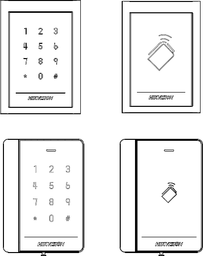
2.1 Front View
The front view of DS-K1101 series card reader is shown below:
Figure 2-1 DS-K1101MK/DS-K1101CK
Figure 2-2 DS-K1101M/DS-K1101C
The front view of DS-K1102 series card reader is shown below:
Figure 2-3 DS-K1102MK/DS-K1102CK
Figure 2-4 DS-K1102M/DS-K1102C
5
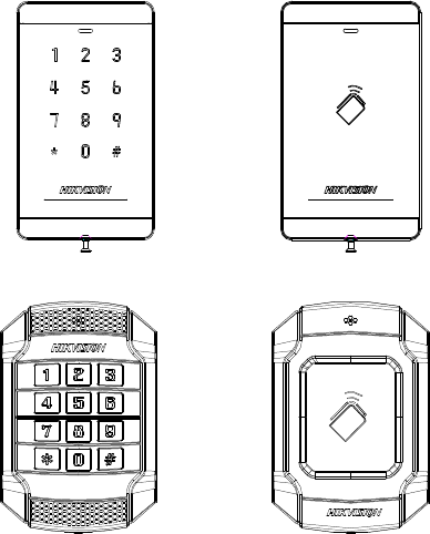
The front view of DS-K1103 series card reader is shown below:
Figure 2-5 DS-K1103MK/DS-K1103CK
Figure 2-6 DS-K1103M/DS-K1103C
The front view of DS-K1104 series card reader is shown below:
Figure 2-7 DS-K1104MK/DS-K1104CK
Figure 2-8 DS-K1104M/DS-K1104C
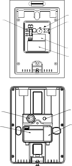
2.2 Rear View
The rear view of card reader is shown below:
6
1
2
3
4
5
Figure 2-9 Rear View of DS-K1101 Series
1
3
4
5
Figure 2-10 Rear View of DS-K1102 Series
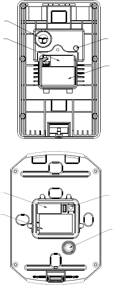
7
3
5
1
4
Figure 2-11 Rear View of DS-K1103 Series
4
5
3
1
Figure 2-12 Rear View of DS-K1104 Series
8
Table 2-1 Description of Rear View
No.
Name
1 Cable Interface of RS-485, Power, LED Control, etc.
2 Buzzer
3 Tamper-proof Module
4 DIP Switch
5 PSAM Card Slot (available for CPU card reader)
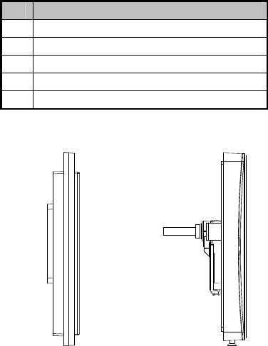
2.3 Side View
The side view of card reader is shown below:
Figure 2-13 DS-K1101 Series Figure 2-14 DS-K1102 Series
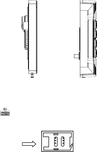
9
Figure 2-15 DS-K1103 Series Figure 2-16 DS-K1104 Series
Chapter 3 Installation
3.1 Installing PSAM Card
PSAM card slot is only available for CPU card reader.
Insert the PSAM card into the slot according to the direction
shown below.
Figure 3-1 PSAM Card Slot
10
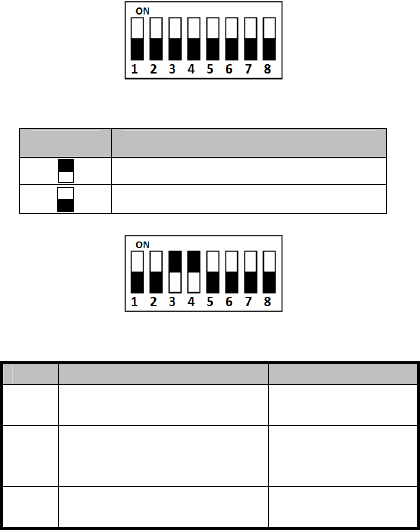
3.2 Introduction for DIP Switch
The DIP switch module is shown below. The No. of DIP switch
from left to right is 1 ~ 8.
Figure 3-2 DIP Switch Module
Table 3-1 Description of DIP Switch
Icon Description
Represent 1 in binary mode
Represent 0 in binary mode
For example, binary value of the following status is: 0000 1100.
Figure 3-3 DIP Switch Module
Table 3-2 Description of DIP Switch
No.
Description
DIP
Switch Status
1 ~ 4 Address of RS-485 1: 1
0: 0
5
Read card No. or file in card.
(Only available for CPU card
read
er.
)
1: read card No;
0: read file in card.
6 Wiegand protocol or RS-485
protocol.
1: Wiegand protocol;
0
: RS
-
485
p
rotocol.
11
No.
Description
DIP
Switch Status
7 Wiegand Protocol
(available when No. 6 is 1)
1: Wiegand protocol
of 26-bit;
0: Wiegand protocol
of 34-bit.
8 Matched Resistance
(available for RS
-
485 protocol)
1: Enable;
0
:
Disable.
3.3 Definition of Cable
The description of 10 cables is shown below.
Table 3-3 Description of Cable
Color
Description
Yellow RS-485+
Brown
Blue LED Control (
ava
ilable for
Wiegand
Protocol)
Blue RS-485-
Purple
Beep Control (
available for
Wiegand
Protocol
)
Gray Case Sensor (available for Wiegand Protocol)
Green
Wiegand W0 (
available for
Wiegand
Protocol
)
White Wiegand W1 (available for Wiegand Protocol)
Black
GND
Orange Red LED Control (available for Wiegand Protocol)
Red PWR (DC +12V)
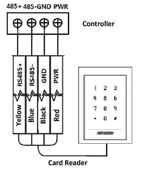
3.4 Wiring Cables
Purpose:
Wire the cables between controller and card reader, thus to
establish the communication between them.
Steps for RS-485 communication mode:
12
1. Set the DIP switch of No. 6 as 0.
2. Set the DIP switch of No. 1 ~ 5 for RS-485 address and
reading card mode. For details, please refer to 3.2
Introduction for DIP Switch.
3. Wire the cable between controller and card reader as
shown below.
Figure 3-4 Wiring for RS-485 Communication Mode
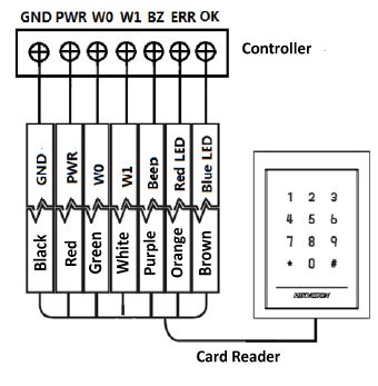
Steps for Wiegand communication mode:
1. Set the DIP switch of No. 6 as 1.
2. Set the DIP switch of No. 5 and 7 for reading card mode and
Wiegand protocol. For details, please refer to 3.2
Introduction for DIP Switch.
13
3. Wiring the cable between controller and card reader as
shown below.
Figure 3-5 Wiring for Wiegand Communication Mode
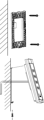
3.5 Installing Card Reader
Before you start:
Set the DIP switch. For details, refer to 3.2 Introduction for DIP
Switch.
Steps:
14
1. Fix the plate on the wall or other
place.
1
2. Connect the cables between
controller and card reader. For
details, refer to 3.4 Wiring
Cables.
2
3
4
3. Push the card reader to match
the fixed plate.
4. Fasten the screw to keep the
components together.
Chapter 4 Sound Prompt and Indicator
After the card reader is powered on, LED status indicator will turn
blue and blink for 1 time. Then it will turn red and blink for 3
times. At last the buzzer will send out a beep sound indicating the
starting up process is completed.
During using the card reader, it will send out different sounds
prompt and the LED indicator on it have different statuses. You
can refer to tables below for detailed information.

15
Table 4-1 Description of Prompt Sound
Sound
Prompt
Description
One beep
RS
-
485 protocol:
Press
ing
keys
prompt
;
Swiping card prompt; Time out prompt for
pressing keys or swiping card.
Wiegand protocol: Pressing keys prompt;
Swiping card prompt.
Two rapid beeps
The operation of p
ressing
keys or swip
ing
card is valid.
Three slow beeps
The operation of p
ress
ing
keys or swip
ing
card is invalid.
Rapidly
continuous beeps Alarm of tamper-proof.
Slowly continuous
beeps The card reader is unencrypted.
Table 4-2 Description of LED Indicator
LED
Indicator Status
Description
Blue and blinking
Card r
ead
er is working normally
.
Solid blue
The operation of pressing keys or swiping
card is valid.
Solid red
The operation of pressing keys or swiping
card is invalid.
Red and blinking
F
or RS
-
485 protocol:
R
egistering failed or
card reader is offline.
Red and
Keeping
rapidly blinking
Available f
or reading file mode of CPU
card: PSAM is not inserted or undetected.
Red
and
keeping
rapidly blinking and
slowly beeps
Failed to get key files of PSAM card; Failed
to detect the PSAM card.

16