Hangzhou Hikvision Digital Technology K3B601LM Swing Barrier User Manual
Hangzhou Hikvision Digital Technology Co., Ltd. Swing Barrier
UserManual.wiki
>
Hangzhou Hikvision Digital Technology
>
K3B601LM User Manual
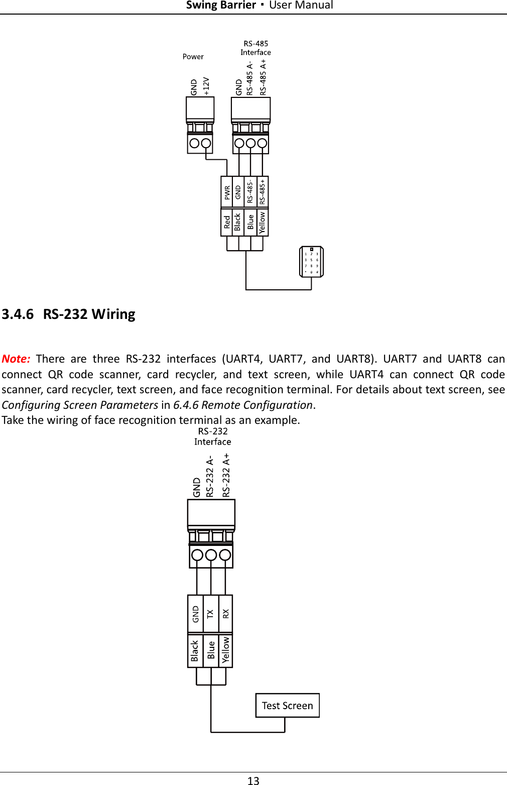
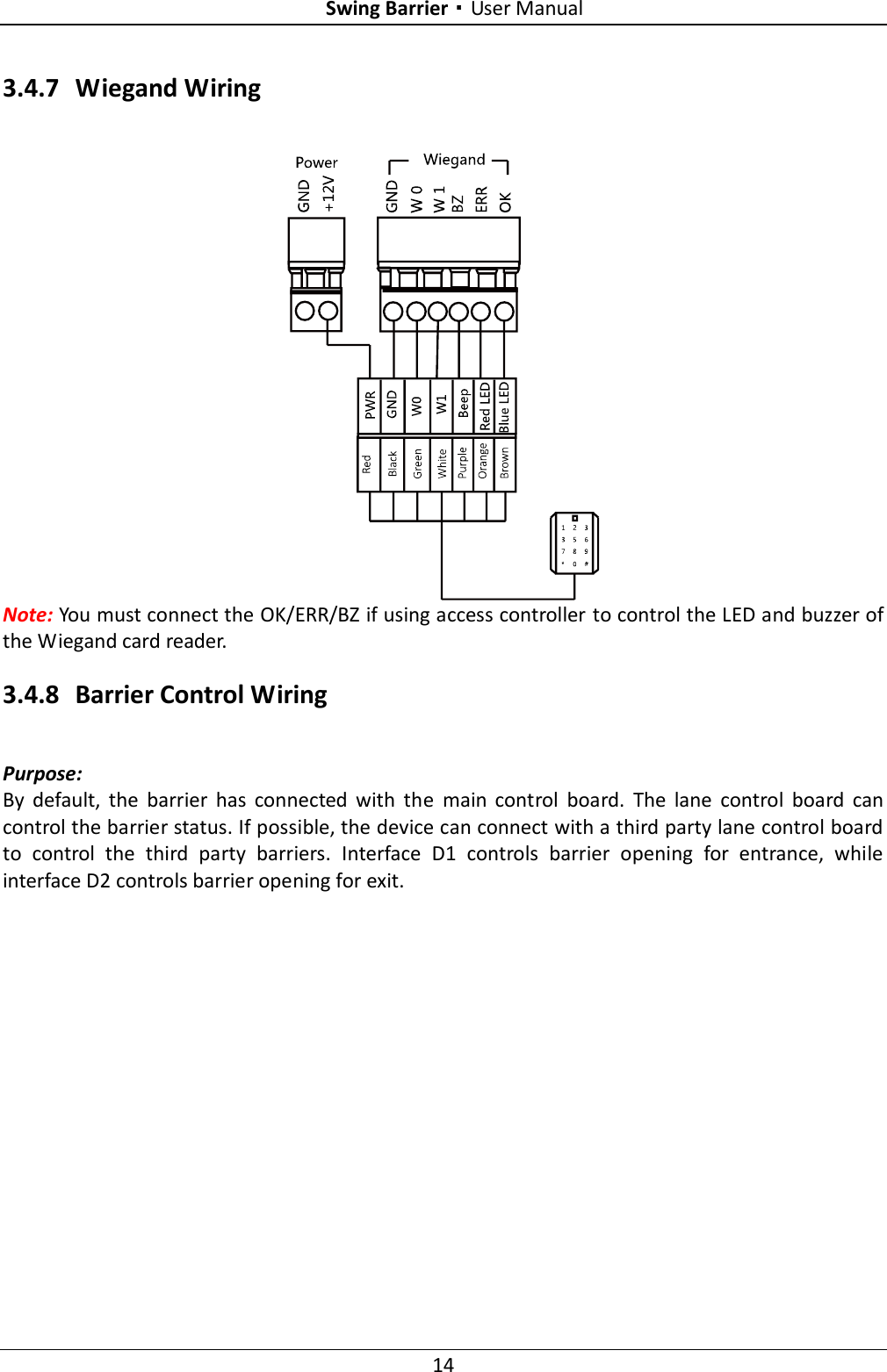
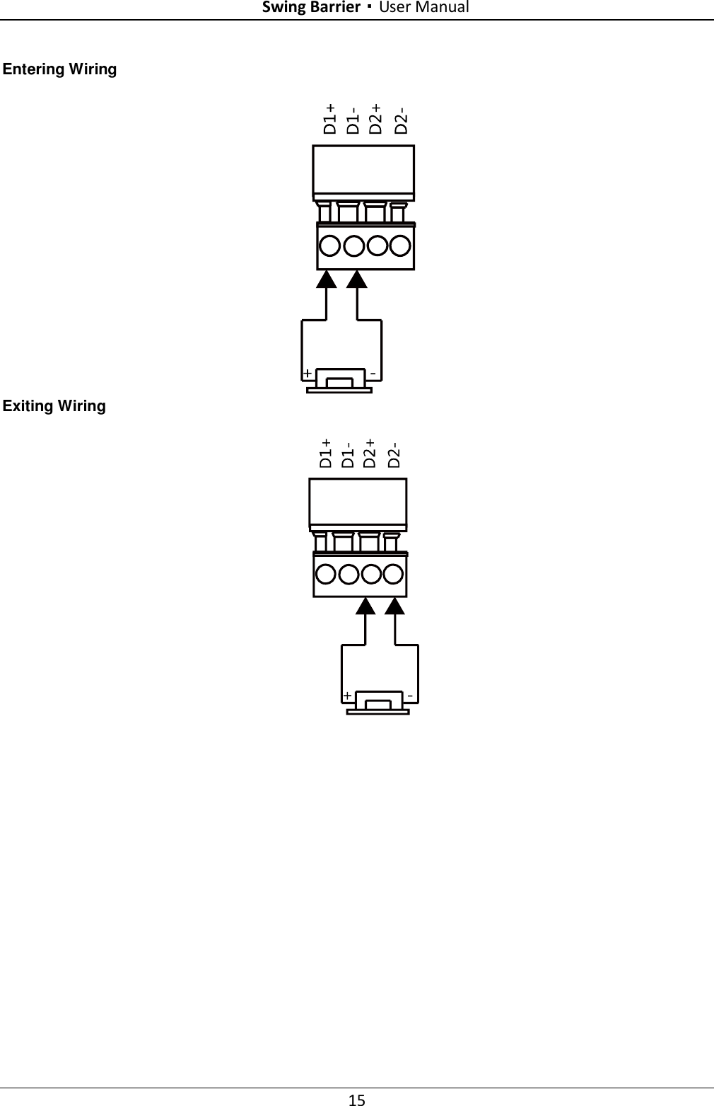
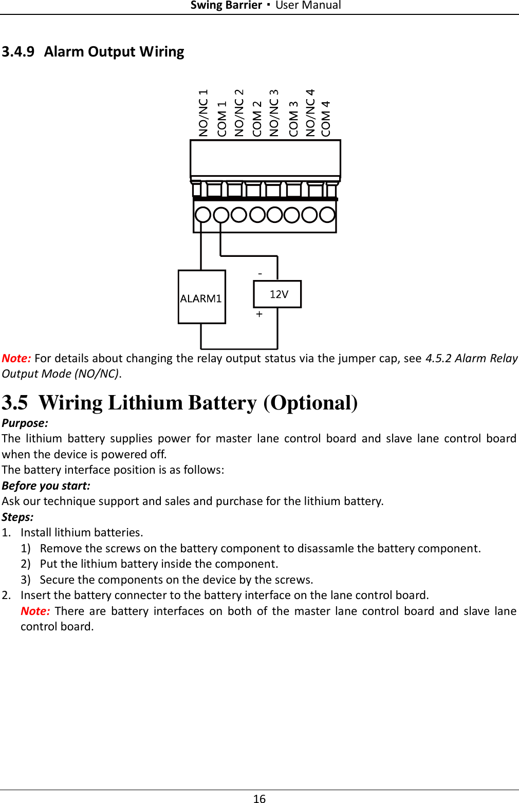
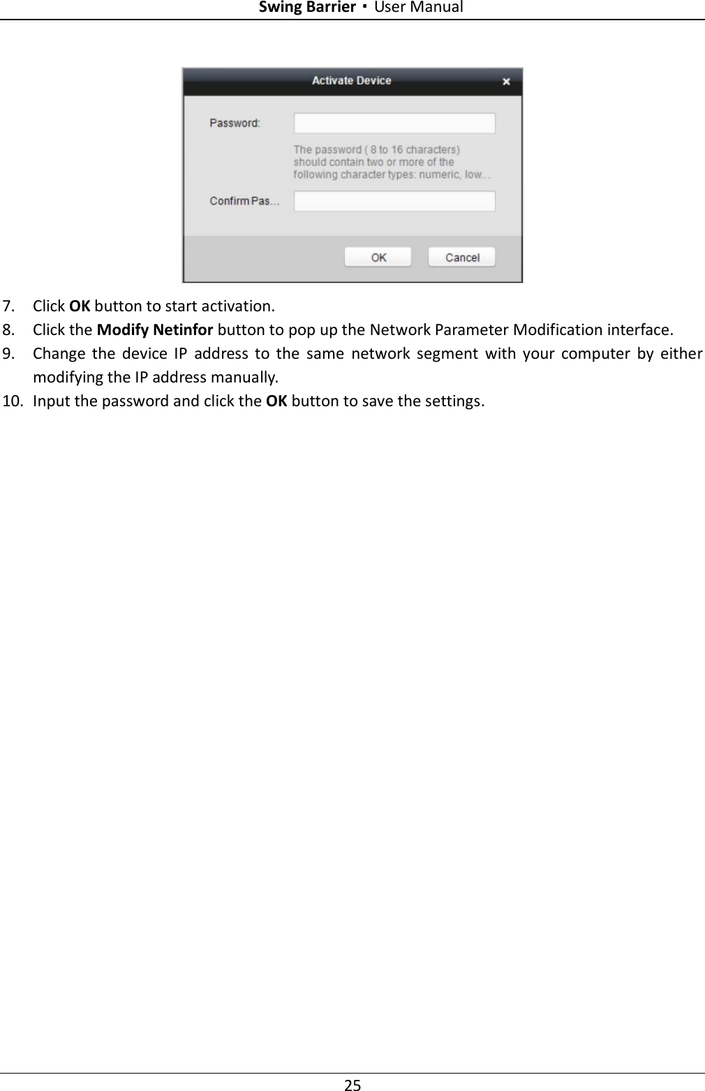
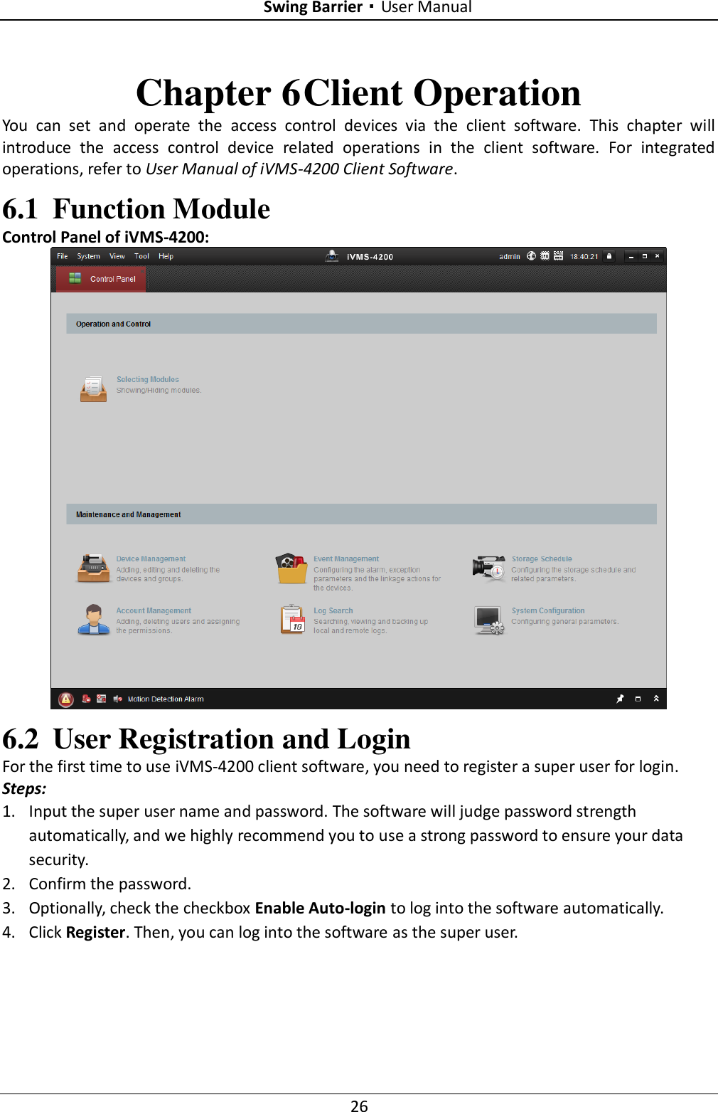
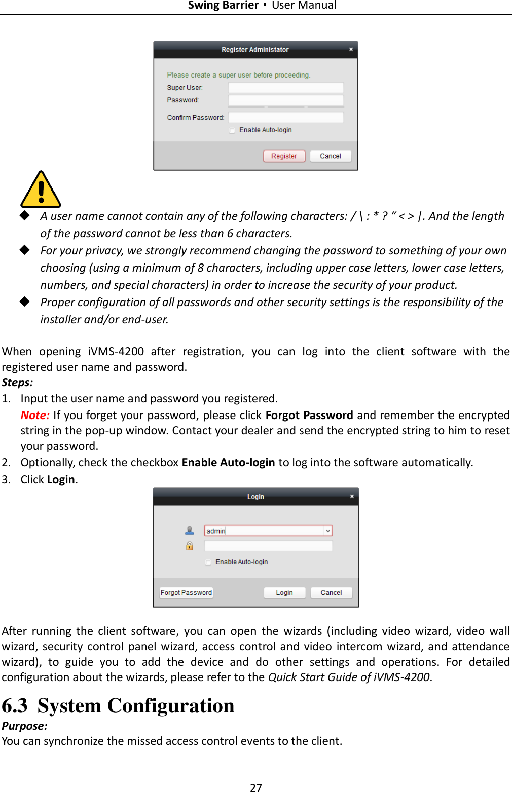
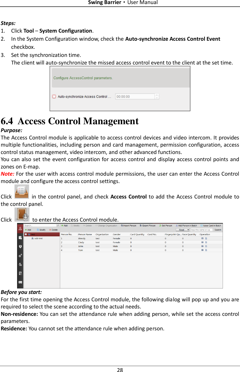
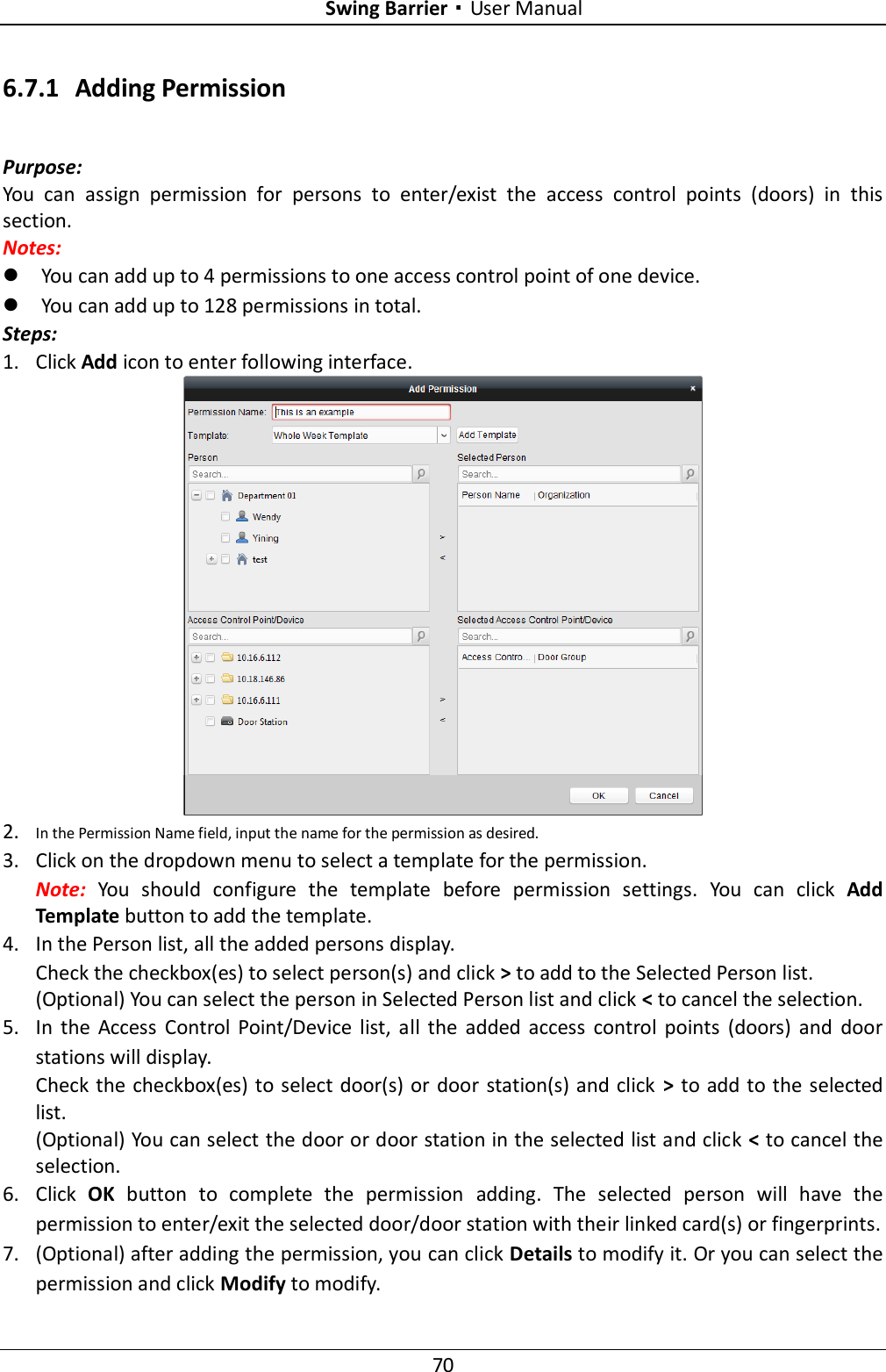
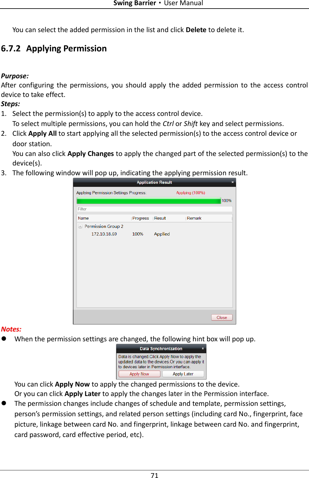
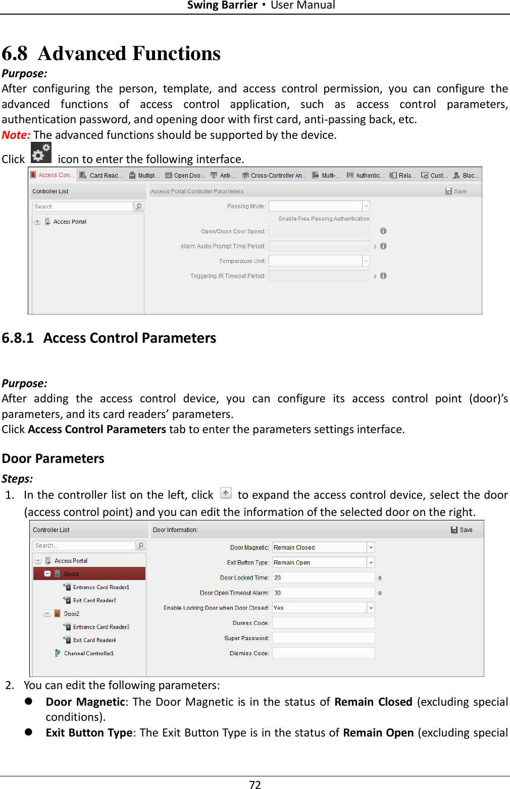
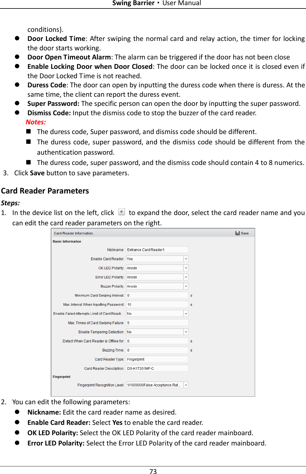
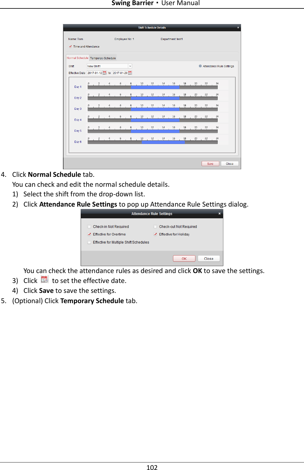
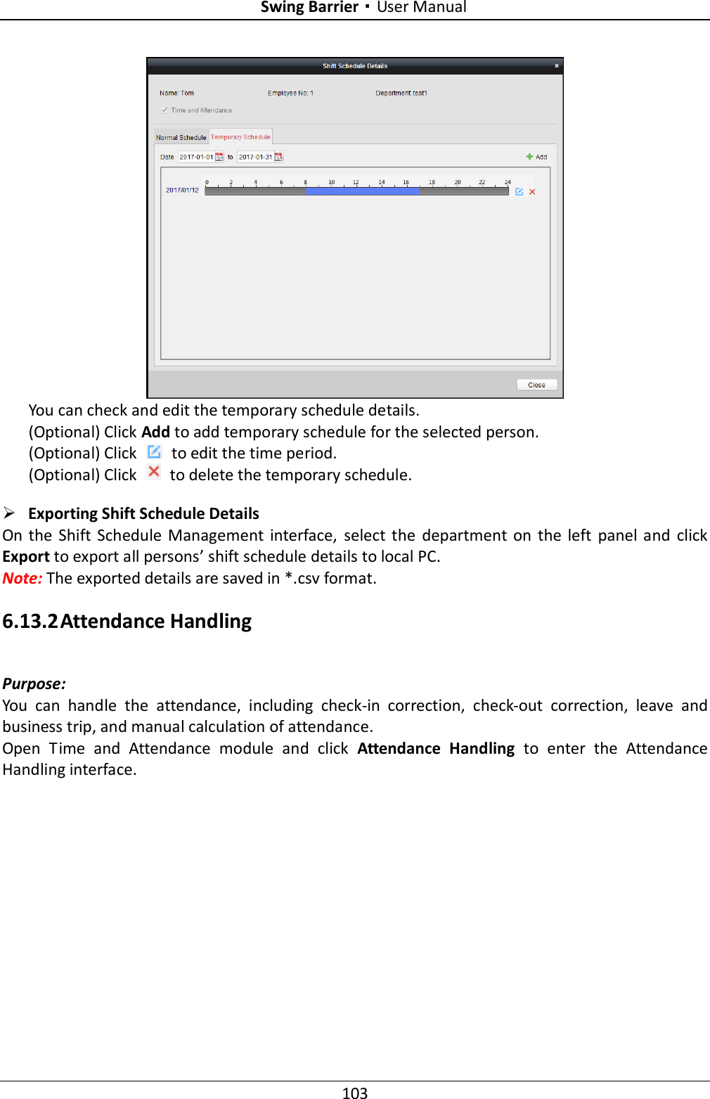
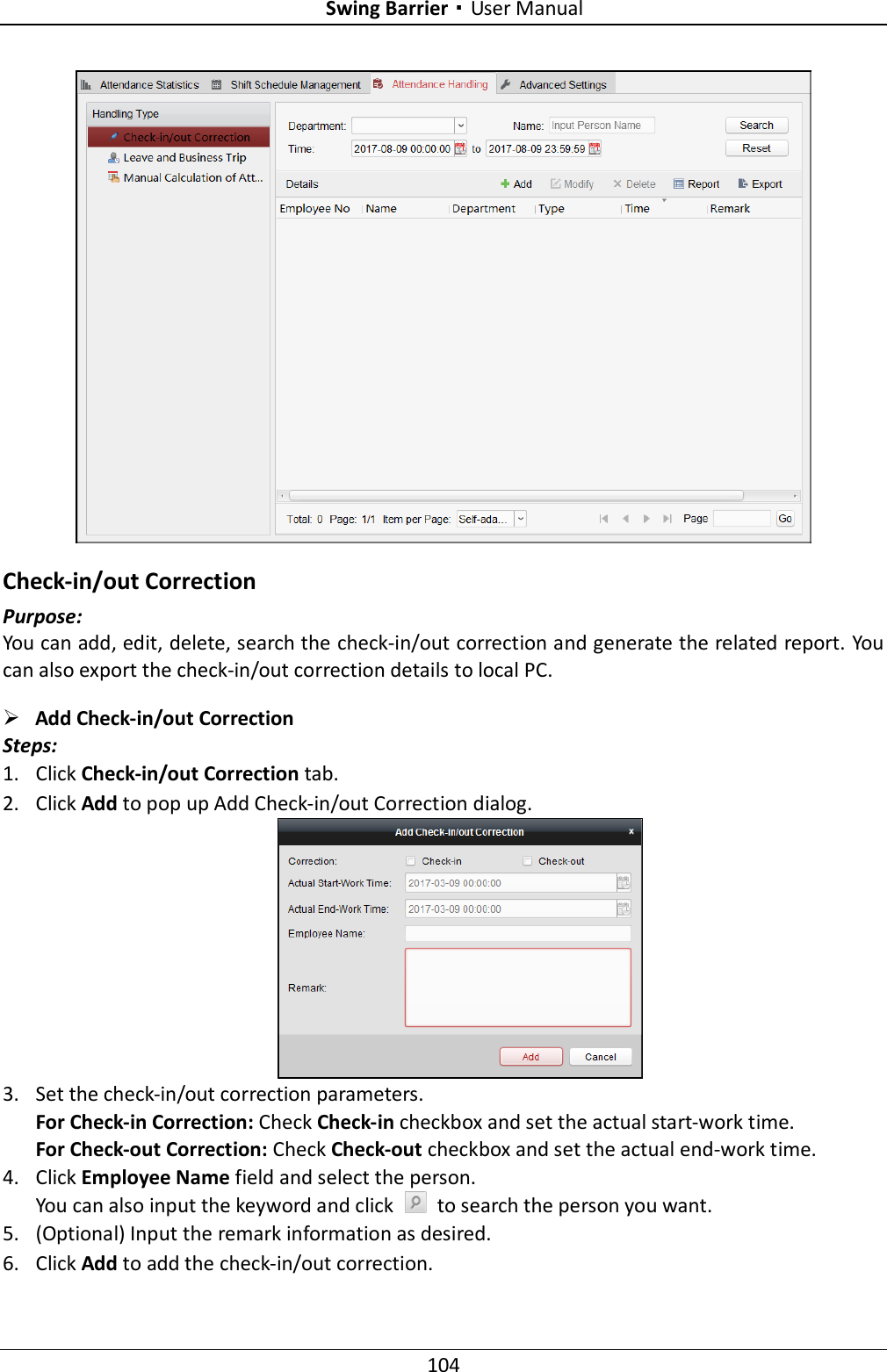
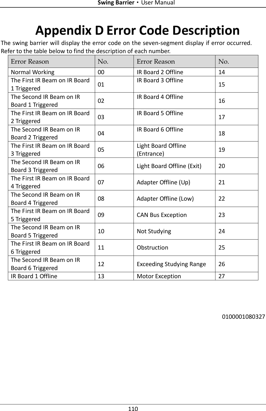
User Manual
Navigation menu
Upload a User Manual
Namespaces
Wiki Guide
HTML
PDF
Info
Views
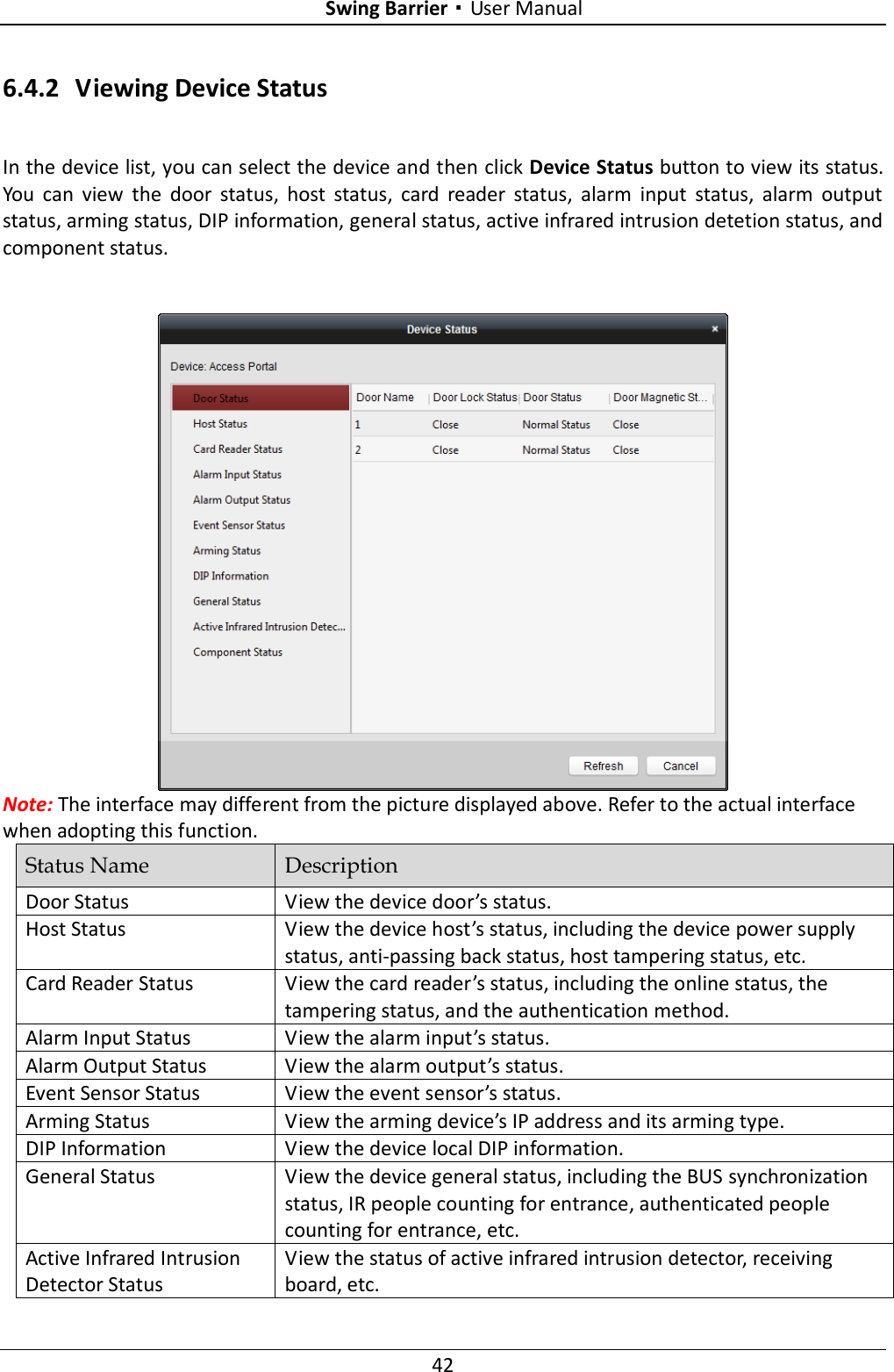
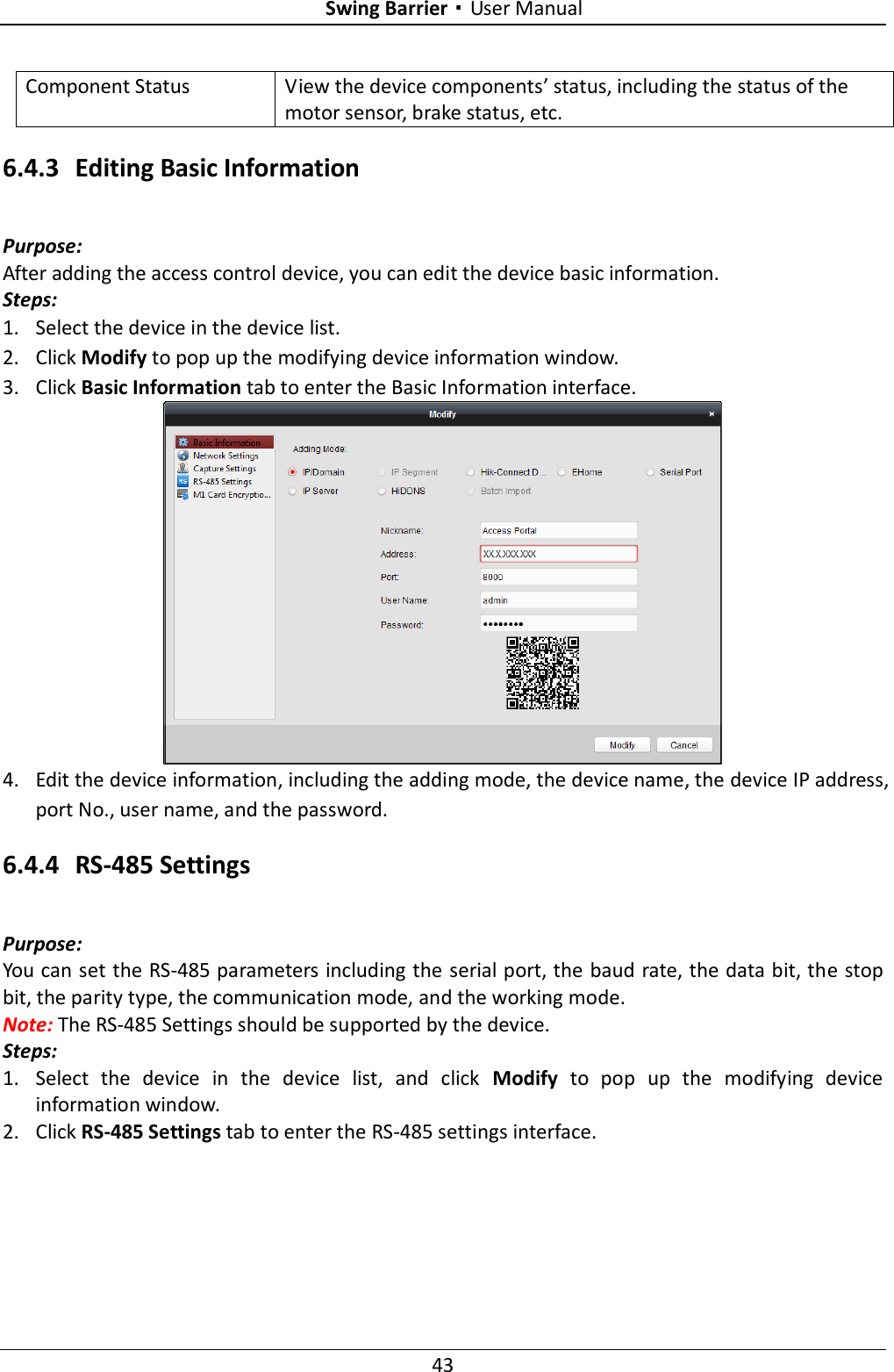
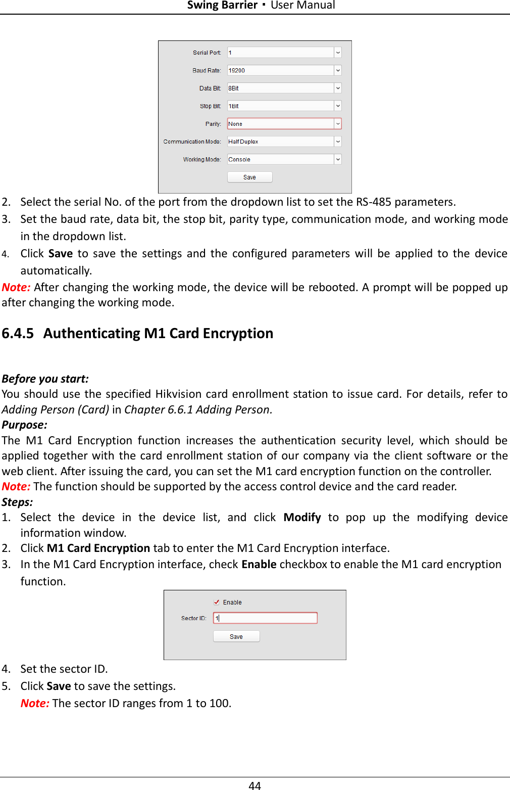
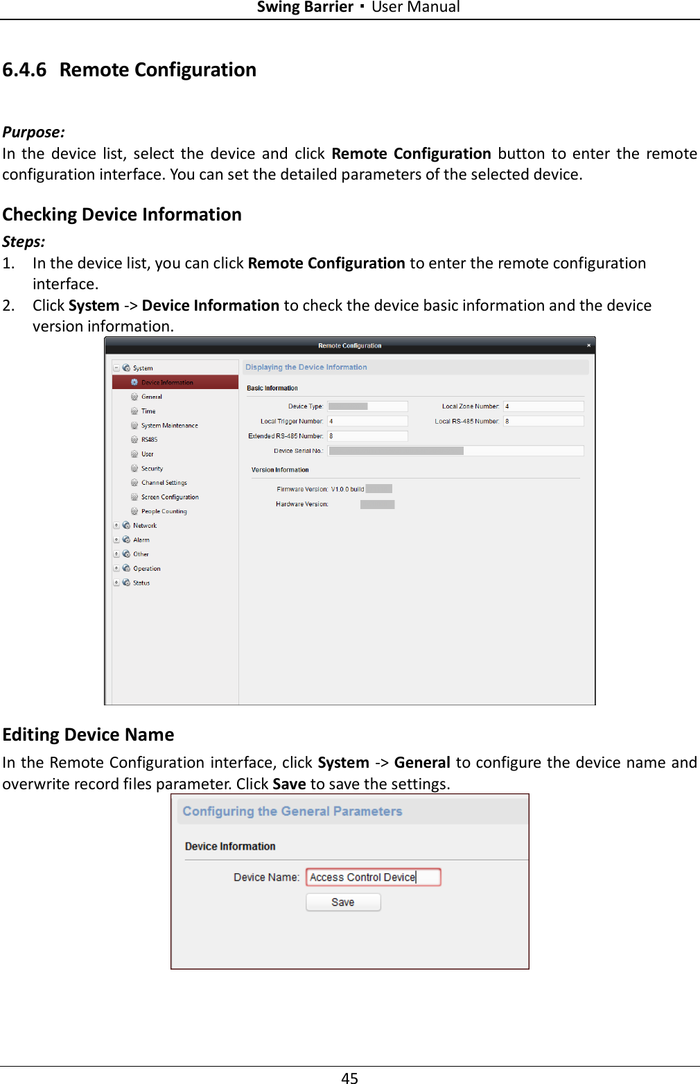
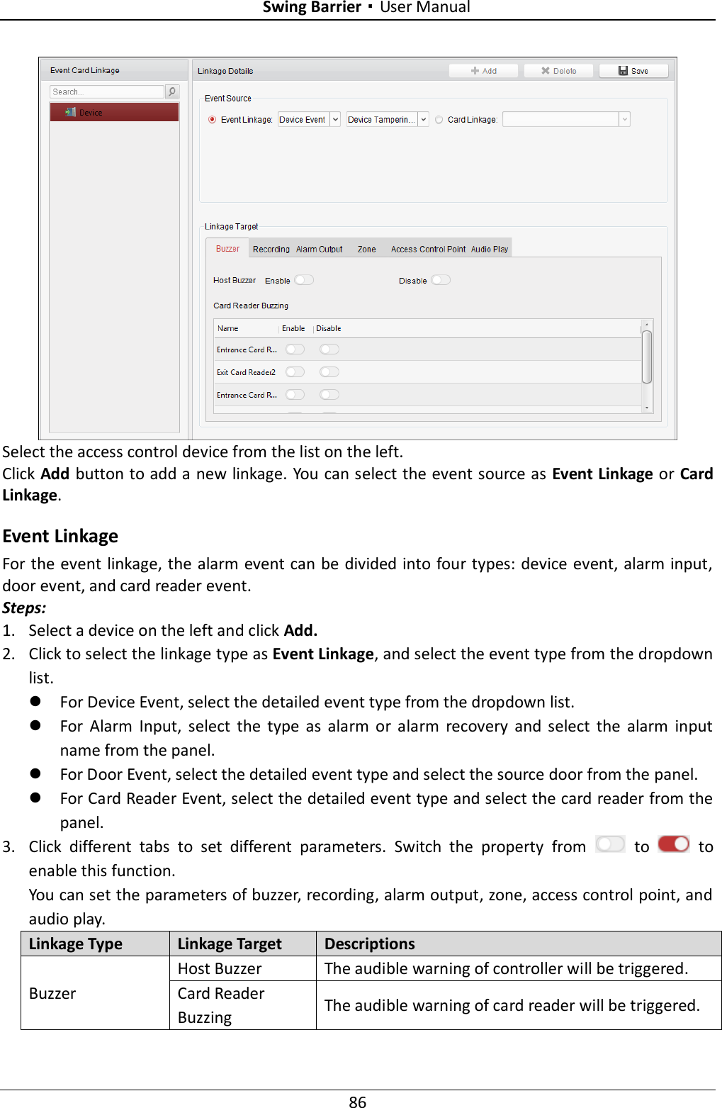
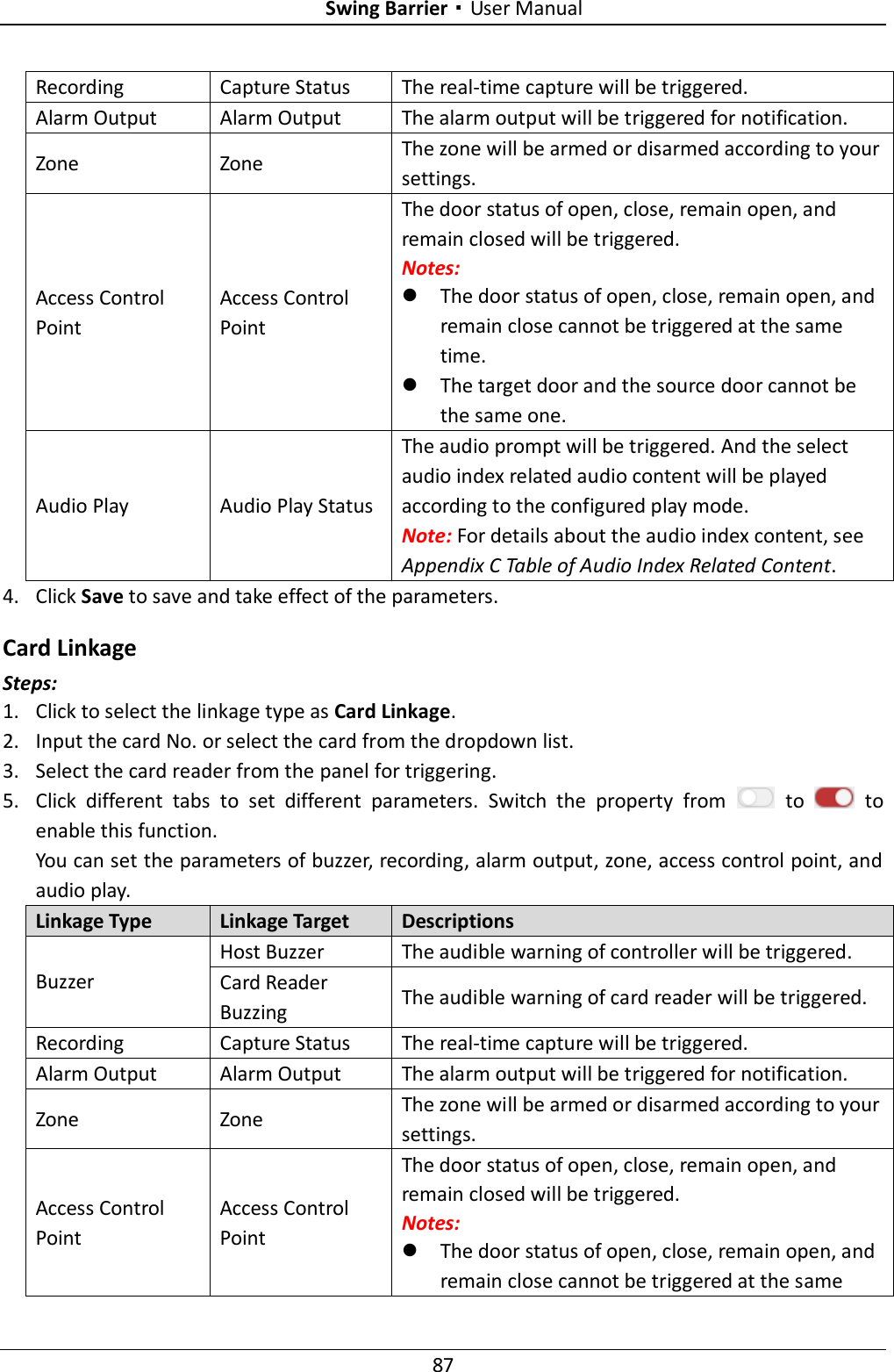
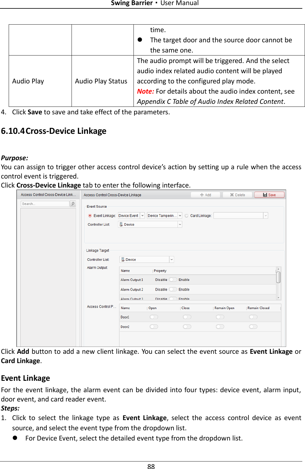
User Manual
Discussion / Help
Navigation