Hangzhou Hikvision Digital Technology MP7608HN Mobile Digital Video Recorder User Manual
Hangzhou Hikvision Digital Technology Co., Ltd. Mobile Digital Video Recorder Users Manual
Users Manual

Mobile NVR
User Manual

Mobile Network Video Recorder User Manual
1
TABLE OF CONTENTS
Chapter 1 Panel Introduction ............................................................................................................................................. 9
1.1 Front Panel ................................................................................................................................................................... 9
1.2 Rear Panel ................................................................................................................................................................... 10
Chapter 2 Installation and Connections ............................................................................................................................ 12
2.1 Environment ............................................................................................................................................................... 12
2.2 Install HDD .................................................................................................................................................................. 12
2.3 Install SIM Card ........................................................................................................................................................... 16
2.4 Install SD Card ............................................................................................................................................................. 16
2.5 Install Antenna ............................................................................................................................................................ 17
2.6 Power Cord Wiring ..................................................................................................................................................... 19
2.6.1 Shutdown Delay ............................................................................................................................................... 19
2.6.2 Scheduled Shutdown ....................................................................................................................................... 20
2.7 Alarm Input/Output Connection ................................................................................................................................ 21
2.7.1 Alarm Input Connection .................................................................................................................................. 21
2.7.2 Alarm Output Connection ................................................................................................................................ 22
2.8 Sensor-in Wiring ......................................................................................................................................................... 22
2.9 Power-on .................................................................................................................................................................... 22
Chapter 3 Start Up Device ................................................................................................................................................ 24
3.1 Startup ........................................................................................................................................................................ 24
3.2 Activation.................................................................................................................................................................... 24
Chapter 4 Network........................................................................................................................................................... 26
4.1 Set Local Network ....................................................................................................................................................... 26
4.2 Connect Wireless Network ......................................................................................................................................... 26
4.2.1 3G/4G Dialing ................................................................................................................................................... 26
4.2.2 Set Wi-Fi .......................................................................................................................................................... 27
4.2.3 Set Wi-Fi AP ..................................................................................................................................................... 28
4.3 Firewall Settings ......................................................................................................................................................... 29
Chapter 5 IP Camera Management ................................................................................................................................... 31
5.1 Activate IP Camera ...................................................................................................................................................... 31
5.1.1 Auto Activation ................................................................................................................................................ 31
5.1.2 Manual Activation............................................................................................................................................ 31
5.2 Add IP Camera ............................................................................................................................................................ 33
5.2.1 Quick Add ........................................................................................................................................................ 33
5.2.2 Manual Add ..................................................................................................................................................... 33
5.2.3 Edit Protocol .................................................................................................................................................... 34
5.3 Edit IP Camera ............................................................................................................................................................ 34
5.4 Delete IP Camera ........................................................................................................................................................ 35
Chapter 6 Camera Management ...................................................................................................................................... 36
6.1 Basic Image Settings ................................................................................................................................................... 36
6.1.1 Set OSD Parameters ......................................................................................................................................... 36
6.1.2 Set Image Parameters ...................................................................................................................................... 36
6.2 Set Privacy Mask ......................................................................................................................................................... 37

Mobile Network Video Recorder User Manual
2
6.3 Set Mirror Type ........................................................................................................................................................... 38
Chapter 7 Live View ......................................................................................................................................................... 40
7.1 Preview Settings ......................................................................................................................................................... 40
7.2 Set Camera Order ....................................................................................................................................................... 40
7.3 Right-Click Menu......................................................................................................................................................... 42
7.4 PTZ Operation ............................................................................................................................................................. 42
7.4.1 Configure PTZ Settings ..................................................................................................................................... 42
7.4.2 PTZ Control Panel............................................................................................................................................. 43
Chapter 8 Storage ............................................................................................................................................................ 44
8.1 Storage Settings .......................................................................................................................................................... 44
8.1.1 Format HDD ..................................................................................................................................................... 44
8.1.2 Configure Overwrite ........................................................................................................................................ 44
8.1.3 Configure Picture Partition .............................................................................................................................. 45
8.1.4 View S.M.A.R.T. Information ............................................................................................................................ 45
8.2 Recording Settings ...................................................................................................................................................... 46
8.2.1 Configure Record Settings................................................................................................................................ 46
8.2.2 Configure Motion Detection Recording ........................................................................................................... 48
8.2.3 Configure Alarm Triggered Recording .............................................................................................................. 48
8.2.4 Configure Alarm Terminal ................................................................................................................................ 49
8.2.5 Configure Schedule .......................................................................................................................................... 50
8.3 Sensor-in Settings ....................................................................................................................................................... 50
Chapter 9 Playback .......................................................................................................................................................... 52
9.1 Instant Playback .......................................................................................................................................................... 52
9.2 Play Video by File ....................................................................................................................................................... 52
Chapter 10 Platform ......................................................................................................................................................... 54
10.1 Mobile Surveillance Platform ................................................................................................................................... 54
10.2 Guarding Vision ........................................................................................................................................................ 55
10.3 Register Device in Guarding Vision platform ............................................................................................................ 56
Chapter 11 Backup ........................................................................................................................................................... 57
11.1 Manual Backup ......................................................................................................................................................... 57
11.2 Format Backup Device .............................................................................................................................................. 58
Chapter 12 Events and Alarms .......................................................................................................................................... 59
12.1 Configure Motion Detection Alarm .......................................................................................................................... 59
12.2 Configure Alarm Input .............................................................................................................................................. 59
12.3 Configure Alarm Output ........................................................................................................................................... 60
12.4 Configure Alarm Terminal ......................................................................................................................................... 61
12.5 Configure Video Loss Alarm ..................................................................................................................................... 62
12.6 Configure Video Tampering Alarm ........................................................................................................................... 62
12.7 Configure Exception Alarm ....................................................................................................................................... 63
12.8 Configure Satellite Positioning .................................................................................................................................. 64
12.9 Configure G-Sensor Alarm ........................................................................................................................................ 65
12.10 Configure Arming Schedule and Linkage Actions .................................................................................................... 66
12.11 Configure Detection Area ....................................................................................................................................... 66
Chapter 13 User Account Management ............................................................................................................................ 67

Mobile Network Video Recorder User Manual
3
13.1 Add User ................................................................................................................................................................... 67
13.2 Delete User ............................................................................................................................................................... 68
13.3 Edit User ................................................................................................................................................................... 68
Chapter 14 General System Configuration ........................................................................................................................ 69
14.1 Configure Basic Display Settings ............................................................................................................................... 69
14.2 Configure DST Settings ............................................................................................................................................. 69
14.3 Configure NTP ........................................................................................................................................................... 70
14.4 Configure Advanced Display Settings........................................................................................................................ 71
Chapter 15 Maintenance .................................................................................................................................................. 72
15.1 Check Status ............................................................................................................................................................. 72
15.2 View System Information ......................................................................................................................................... 72
15.3 Upgrade the System .................................................................................................................................................. 72
15.3.1 Upgrade by Local USB Flash Disk ................................................................................................................... 73
15.3.2 Upgrade by Remote FTP server ...................................................................................................................... 73
15.4 Log Operation ........................................................................................................................................................... 74
15.4.1 Search Log File ............................................................................................................................................... 74
15.4.2 Export Log File ............................................................................................................................................... 75
15.5 Restore Default Settings ........................................................................................................................................... 75
15.6 Import/Export Configuration File ............................................................................................................................. 76
15.6.1 Import Configuration File .............................................................................................................................. 76
15.6.2 Export Configuration File ............................................................................................................................... 76
15.7 Serial Port Settings.................................................................................................................................................... 77
Chapter 16 Shut Down Device .......................................................................................................................................... 79
16.1 Enable Scheduled Startup/Shutdown ....................................................................................................................... 79
16.2 Configure Delayed Shutdown ................................................................................................................................... 79
16.3 Reboot ...................................................................................................................................................................... 80
Chapter 17 Remote Control .............................................................................................................................................. 81
17.1 Buttons Description .................................................................................................................................................. 81
17.2 Operation Introduction ............................................................................................................................................. 82
17.2.1 Build Connection with Device (Device No.: 255) ........................................................................................... 83
17.2.2 Build Connection with Device (Device No. is not 255) ................................................................................... 83
17.2.3 Enter Contents in Text Field ........................................................................................................................... 83
17.2.4 Click a Button ................................................................................................................................................. 83
17.2.5 Check a Checkbox .......................................................................................................................................... 83
17.2.6 Select an Item from a Dropdown List ............................................................................................................ 83
17.3 Troubleshooting ........................................................................................................................................................ 84
17.4 Set Areas with Remote Control ................................................................................................................................. 84
Chapter 18 Appendix ....................................................................................................................................................... 85
18.1 Glossary .................................................................................................................................................................... 85
18.2 FAQ ........................................................................................................................................................................... 86

Mobile Network Video Recorder User Manual
4
User Manual
COPYRIGHT © 2018 Hangzhou Hikvision Digital Technology Co., Ltd.
ALL RIGHTS RESERVED.
Any and all information, including, among others, wordings, pictures, graphs are the
properties of Hangzhou Hikvision Digital Technology Co., Ltd. or its subsidiaries (hereinafter
referred to be “Hikvision”). This user manual (hereinafter referred to be “the Manual”)
cannot be reproduced, changed, translated, or distributed, partially or wholly, by any means,
without the prior written permission of Hikvision. Unless otherwise stipulated, Hikvision
does not make any warranties, guarantees or representations, express or implied, regarding
to the Manual.
About this Manual
This Manual is applicable to Mobile Network Video Recorder.
The Manual includes instructions for using and managing the product. Pictures, charts,
images and all other information hereinafter are for description and explanation only. The
information contained in the Manual is subject to change, without notice, due to firmware
updates or other reasons. Please find the latest version in the company website
(http://overseas.hikvision.com/en/).
Please use this user manual under the guidance of professionals.
Trademarks Acknowledgement
and other Hikvision’s trademarks and logos are the properties of Hikvision in
various jurisdictions. Other trademarks and logos mentioned below are the properties of
their respective owners.
Legal Disclaimer
TO THE MAXIMUM EXTENT PERMITTED BY APPLICABLE LAW, THE PRODUCT DESCRIBED,
WITH ITS HARDWARE, SOFTWARE AND FIRMWARE, IS PROVIDED “AS IS”, WITH ALL FAULTS
AND ERRORS, AND HIKVISION MAKES NO WARRANTIES, EXPRESS OR IMPLIED, INCLUDING
WITHOUT LIMITATION, MERCHANTABILITY, SATISFACTORY QUALITY, FITNESS FOR A
PARTICULAR PURPOSE, AND NON-INFRINGEMENT OF THIRD PARTY. IN NO EVENT WILL
HIKVISION, ITS DIRECTORS, OFFICERS, EMPLOYEES, OR AGENTS BE LIABLE TO YOU FOR ANY
SPECIAL, CONSEQUENTIAL, INCIDENTAL, OR INDIRECT DAMAGES, INCLUDING, AMONG
OTHERS, DAMAGES FOR LOSS OF BUSINESS PROFITS, BUSINESS INTERRUPTION, OR LOSS OF
DATA OR DOCUMENTATION, IN CONNECTION WITH THE USE OF THIS PRODUCT, EVEN IF
HIKVISION HAS BEEN ADVISED OF THE POSSIBILITY OF SUCH DAMAGES.
REGARDING TO THE PRODUCT WITH INTERNET ACCESS, THE USE OF PRODUCT SHALL BE
WHOLLY AT YOUR OWN RISKS. HIKVISION SHALL NOT TAKE ANY RESPONSIBILITES FOR
ABNORMAL OPERATION, PRIVACY LEAKAGE OR OTHER DAMAGES RESULTING FROM CYBER
ATTACK, HACKER ATTACK, VIRUS INSPECTION, OR OTHER INTERNET SECURITY RISKS;
HOWEVER, HIKVISION WILL PROVIDE TIMELY TECHNICAL SUPPORT IF REQUIRED.
SURVEILLANCE LAWS VARY BY JURISDICTION. PLEASE CHECK ALL RELEVANT LAWS IN YOUR
JURISDICTION BEFORE USING THIS PRODUCT IN ORDER TO ENSURE THAT YOUR USE
CONFORMS THE APPLICABLE LAW. HIKVISION SHALL NOT BE LIABLE IN THE EVENT THAT
THIS PRODUCT IS USED WITH ILLEGITIMATE PURPOSES.
IN THE EVENT OF ANY CONFLICTS BETWEEN THIS MANUAL AND THE APPLICABLE LAW, THE
LATER PREVAILS.

Mobile Network Video Recorder User Manual
5
Regulatory Information
FCC Information
This device complies with Part 15 of the FCC Rules.
Operation is subject to the following two
conditions:
(1) This device may not cause harmful interference, and
(2)
This device must accept any interference received, including interference that may
cause undesired operation.
Note: This product has been tested and found to comply with the limits for a Class B digital
device, pursuant to Part 15 of the FCC Rules. These limits are designed to provide
reasonable protection against harmful interference in a residential installation. This product
generates, uses, and can radiate radio frequency energy and, if not installed and used in
accordance with the instructions, may cause harmful interference to radio communications.
However, there is no guarantee that interference will not occur in a particular installation. If
this product does cause harmful interference to radio or television reception, which can be
determined by turning the equipment off and on, the user is encouraged to try to correct the
interference by one or more of the following measures:
—Reorient or relocate the receiving antenna.
—Increase the separation between the equipment and receiver.
—Connect the equipment into an outlet on a circuit different from that to which the receiver
is connected.
—Consult the dealer or an experienced radio/TV technician for help.
Please take attention that changes or modification not expressly approved by the party
responsible for compliance could void the user’s authority to operate the
equipment.
This equipment complies with FCC/IC RSS-102 radiation exposure limits set forth for an
uncontrolled environment. This eqipment should be installed and operated with minimum
distance 20cm between the radiator & your body.
EU Conformity Statement
This product and - if applicable - the supplied accessories too are marked with "CE"
and comply therefore with the applicable harmonized European standards listed
under the EMC Directive 2014/30/EU, the LVD Directive 2014/35/EU, the RoHS Directive
2011/65/EU.

Mobile Network Video Recorder User Manual
6
documentation for specific battery information. The battery is marked with this symbol,
which may include lettering to indicate cadmium (Cd), lead (Pb), or mercury (Hg). For proper
recycling, return the battery to your supplier or to a designated collection point. For more
information see: www.recyclethis.info
2012/19/EU (WEEE directive): Products marked with this symbol cannot be
disposed of as unsorted municipal waste in the European Union. For proper
recycling, return this product to your local supplier upon the purchase of
equivalent new equipment, or dispose of it at designated collection points. For more
information see: www.recyclethis.info
2006/66/EC (battery directive): This product contains a battery that cannot be
disposed of as unsorted municipal waste in the European Union. See the product
Mobile Network Video Recorder User Manual
7
Applicable Models
This manual is applicable to the models listed in the following table.
Series
Model
DS-MP7608HN
DS-MP7608HN
DS-MP7608HN/GW
DS-MP7608HN/GW/WI
DS-MP7608HN/GW/WI58
Symbol Conventions
The symbols that may be found in this document are defined as follows.
Symbol
Description
Provides additional information to emphasize or supplement
important points of the main text.
Indicates a potentially hazardous situation, which if not avoided,
could result in equipment damage, data loss, performance
degradation, or unexpected results.
Indicates a hazard with a high level of risk, which if not avoided, will
result in death or serious injury.

Mobile Network Video Recorder User Manual
8
Safety Instructions
Proper configuration of all passwords and other security settings is the responsibility of
the installer and/or end-user.
In the use of the product, you must be in strict compliance with the electrical safety
regulations of the nation and region. Please refer to technical specifications for detailed
information.
Input voltage should meet both the SELV (Safety Extra Low Voltage) and the Limited
Power Source with 9 to 32 VDC according to the IEC60950-1 standard. Please refer to
technical specifications for detailed information.
Do not connect several devices to one power adapter as adapter overload may cause
over-heating or a fire hazard.
Please make sure that the plug is firmly connected to the power socket.
If smoke, odor or noise rise from the device, turn off the power at once and unplug the
power cable, and then please contact the service center.
Preventive and Cautionary Tips
Before connecting and operating your device, please be advised of the following tips:
Ensure unit is installed in a well-ventilated, dust-free environment.
Keep all liquids away from the device.
Ensure environmental conditions meet factory specifications.
Ensure unit is properly secured to a rack or shelf. Major shocks or jolts to the unit as a
result of dropping it may cause damage to the sensitive electronics within the unit.
Use the device in conjunction with an UPS if possible.
Power down the unit before connecting and disconnecting accessories and peripherals.
A factory recommended HDD should be used for this device.
Improper use or replacement of the battery may result in hazard of explosion. Replace
with the same or equivalent type only. Dispose of used batteries according to the
instructions provided by the battery manufacturer.
Mobile Network Video Recorder User Manual
9
Chapter 1 Panel Introduction
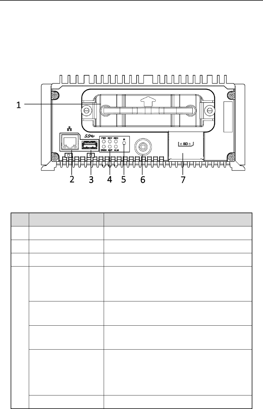
1.1 Front Panel
Figure 1-1 Front Panel
Table 1-1 Interface Description
No.
Name
Description
1
Dummy HDD
Two HDDs can be installed.
2
Network interface
10M/100M/1000M RJ45 Ethernet interface.
3
USB 3.0
USB 3.0 interface.
4
PWR
Power indicator.
Solid green: Device is powered on.
Solid red: Device is standby.
RDY
Ready indicator.
Solid green: Device starts up normally.
REC
Recording indicator.
Solid green: Device is recording normally.
GNSS
GNSS indicator.
Unlit: Positioning module is abnormal.
Solid green: Device is positioning.
Flashing green: Positioning succeeded.
ANT
ANT indicator.
Mobile Network Video Recorder User Manual
10
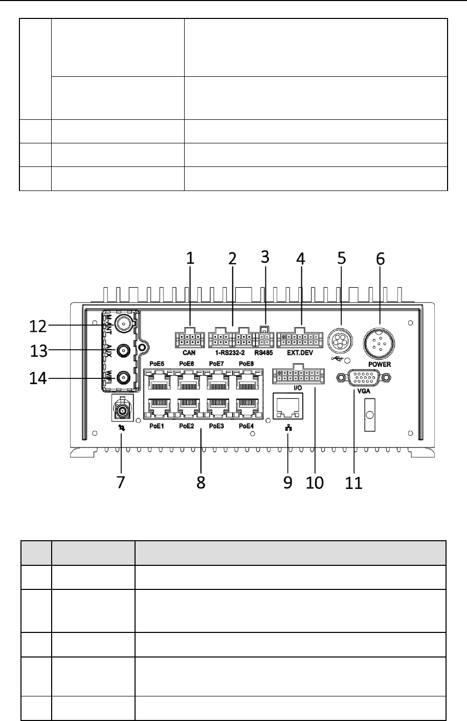
1.2 Rear Panel
Figure 1-2 Rear Panel
Table 1-2 Interface Description
Unlit: Dialing module is abnormal.
Solid green: Device is dialing.
Flashing green: Dialing up succeeded.
ALM
Alarm indicator.
Red: Alarm occurs.
5
IR receiver
IR receiver for remote control.
6
Dummy HDD lock
Lock/unlock the dummy HDD.
7
SD card slot
Slot for SD card.
No.
Name
Description
1
CAN
2 × CAN interface.
2
RS-232
The left one is for debugging.
The right one is for connecting external devices.
3
RS-485
RS-485 interface for connecting devices like speed dome.
4
EXT.DEV
RS-422 communication interface, two-way audio interface,
and CVBS video output.
5
USB interface
USB interface of 5-pin aviation plug.

Mobile Network Video Recorder User Manual
11
6
Power
6-pin aviation plug for power supply.
7
GNSS antenna
GNSS antenna interface.
8
PoE 1 to 8
8 × PoE interface.
9
Network
interface
1 × 10M/100M/1000M RJ45 Ethernet interface.
10
I/O
4-ch alarm input, 2-ch alarm output, 4-ch sensor in, 1-ch
pulse signal input.
11
VGA
VGA video output interface.
12
M-ANT
Main 3G/4G antenna interface.
13
AUX
Aux Wi-Fi antenna interface.
14
WIFI
Main Wi-Fi antenna interface.
Mobile Network Video Recorder User Manual
12
Chapter 2 Installation and Connections
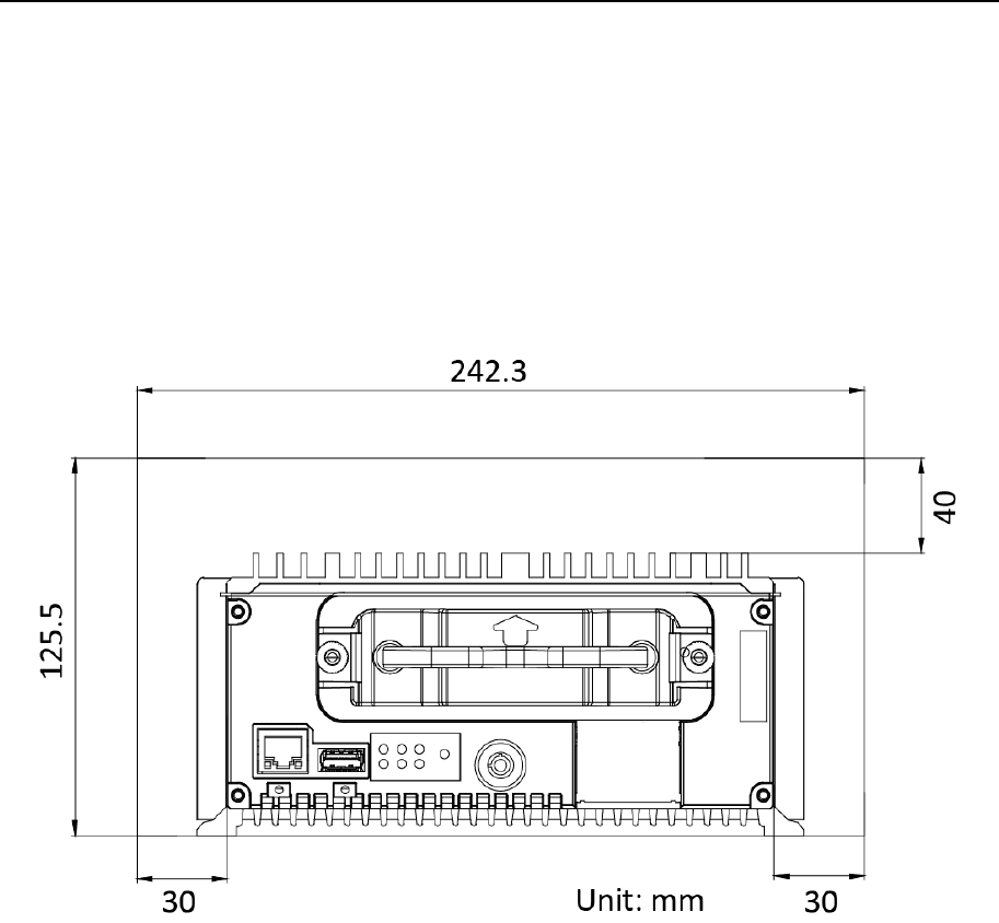
2.1 Environment
To ensure the device can ventilate well, find a position with enough space. Recommended
installation space is shown in Figure 2-1.
Figure 2-1 Recommended Installation Space
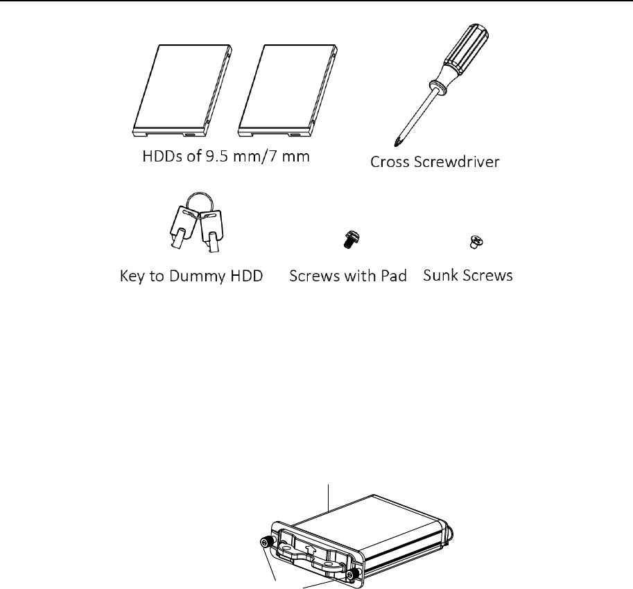
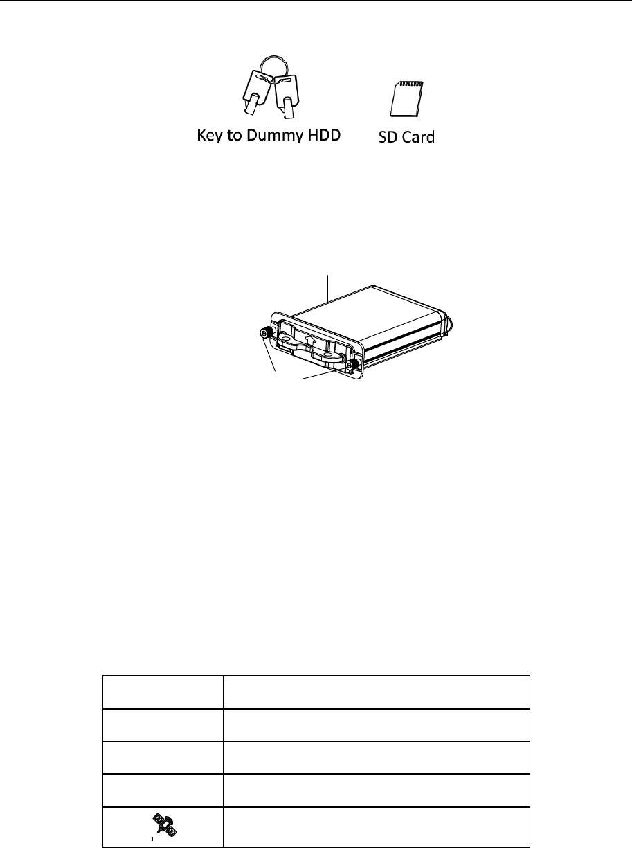
2.2 Install HDD
Before You Start:
Prepare the tools and components for installation:
Factory recommended 2.5-inch HDD.
Antistatic gloves.
Key to dummy HDD (delivered with device).
Cross screwdriver.
Screws (delivered with device).
Mobile Network Video Recorder User Manual
13
Figure 2-2 Tools
Purpose:
Perform the following steps to install the HDD on the device. Figures in following steps are
only for reference.
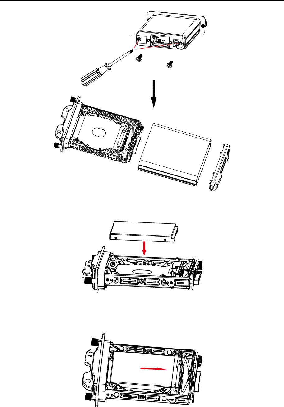
Step 1 Insert the key and turn counterclockwise to unlock dummy HDD.
Step 2 Unfasten the two screws of dummy HDD and pull dummy HDD out of device.
Unfasten Screws
Dummy HDD
Figure 2-3 Pull Dummy HDD out
Step 3 Use cross screwdriver to loosen the two screws and remove them, and then take the
dummy HDD apart.
Mobile Network Video Recorder User Manual
14
Figure 2-4 Take Apart Dummy HDD
Step 4 Place the first HDD into the dummy HDD, with the PCB facing down.
Figure 2-5 Place HDD
Step 5 Push the HDD along the direction shown in Figure 2-6 to connect HDD with socket of
dummy HDD.
Figure 2-6 Push HDD
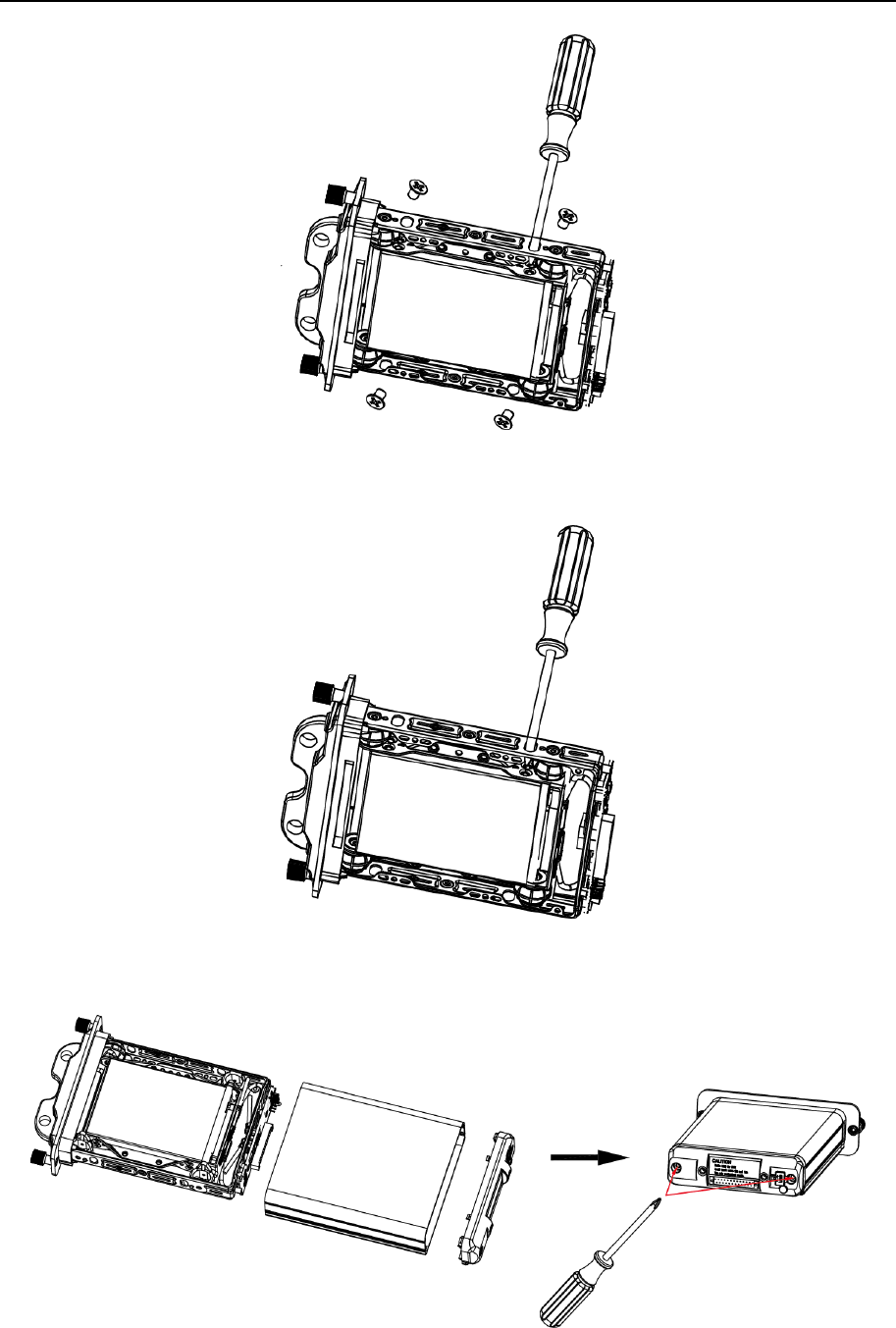
Step 6 Use four sunk screws to fix HDD with dummy HDD.
Mobile Network Video Recorder User Manual
15
Figure 2-7 Fix HDD
Step 7 Repeat step 4 to 6 to install the secondary HDD in the other socket of dummy HDD.
Figure 2-8 Install the Other HDD
Step 8 Reassemble the dummy HDD.
Figure 2-9 Reassemble Dummy HDD
Mobile Network Video Recorder User Manual
16
Step 9 Plug the dummy HDD back to the device and then tighten the screws clockwise.
Step 10 Turn the key clockwise to lock dummy HDD.
2.3 Install SIM Card
Purpose:
Pluggable 3G/4G wireless communication module is designed for the device and you should
install the SIM card to realize the wireless communication function.
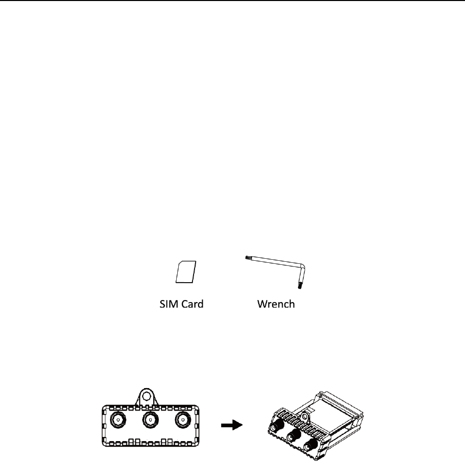
Before You Start
Prepare the tools and components for installation:
SIM card
Wrench
Figure 2-10 Tools
Step 1 Use wrench to unfasten and remove the two screws fixing the 3G/4G and Wi-Fi
module.
Figure 2-11 Unfasten Screws
Step 2 Pull out the 3G/4G and Wi-Fi module.
Step 3 Press the yellow button on the 3G/4G slot and then pull the SIM card tray out.
Step 4 Place the SIM card on SIM card tray.
Step 5 Insert the SIM card tray back to SIM card slot.
Step 6 Install the 3G/4G module back to the device and tighten the set screw.
2.4 Install SD Card
Before You Start
Prepare the tools and components for installation:
Key to dummy HDD (delivered with device)
Mobile Network Video Recorder User Manual
17
SD card
Figure 2-12 Tools
Step 1 Insert the key and turn counterclockwise to unlock dummy HDD.
Step 2 Unfasten the two screws of dummy HDD and pull dummy HDD out of device.
Unfasten Screws
Dummy HDD
Figure 2-13 Unfasten Screws
Step 3 Open the cover of SD card slot.
Step 4 Insert SD card into SD card slot with gold contacts facing down till you hear a click.
Step 5 Plug the dummy HDD back to the device, close the cover of SD card slot, and then
tighten the screws clockwise.
Step 6 Turn the key clockwise to lock dummy HDD.
2.5 Install Antenna
Connect antennas to corresponding antenna interfaces.
Table 2-1 Antenna Interface
Interface
Corresponding Anntena
M-ANT
Main 3G/4G antenna
AUX
Aux Wi-Fi antenna
WIFI
Main Wi-Fi antenna
GNSS/
Positioning anntena
Connect antennas to corresponding antenna interfaces.

Mobile Network Video Recorder User Manual
18
Table 2-2 Antenna Interface
Interface
Corresponding Anntena
M-ANT
Main 3G/4G antenna
AUX
Aux Wi-Fi antenna
WIFI
Main Wi-Fi antenna
GNSS/
Positioning anntena
Place antenna vertically with its signal receiving end facing upward.
If the cable is too long, you can roll them up to prevent signal receiving from being
affected.
Install 3G/4G antenna in car windshield, seat backrest, or other non-metallic objects.
Keep away from metal objects for at least 50 cm.
Vertically install positioning antenna on the automobile roof with no shelter.
Follow the instructions below in case that you need to install positioning antenna inside
your automobile.
Install antenna on platform under the front windshield.
Windshield
Antenna
Figure 2-14 Install Positioning Antenna Inside Automobile
Fix antenna with neutral silica gel.
When adjusting the antenna position, ensure that at least 4 satellites have a signal
strength above 35 dB. You can go to Menu > Status > Position to view positioning
signal status.
Figure 2-15 Positioning Antenna Installation (on Automobile Roof)
Mobile Network Video Recorder User Manual
19
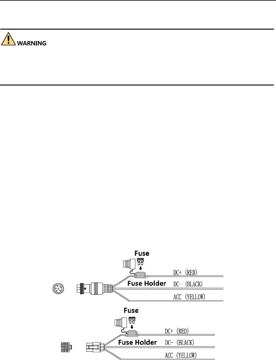
2.6 Power Cord Wiring
In order to ensure the safety of your automobile and device, a fuse is required for wiring of
automobile power and device power.
Do not connect the power cord to the device before all the cables are connected.
2.6.1 Shutdown Delay
Purpose:
The device starts up when your automobile ignites and shuts down after automobile is off.
Automobile ignition startup and shutdown are realized by automobile positive pole ignition
switch (providing high level signal when the switch closes). The wire connection of the device
varies with the automobile ignition models.
Ignition switch is connected to the positive pole of +12/24 VDC of automobile batteries. Make
sure that the connection is correct, and then perform the following steps:
Step 1 Connect the "DC IN +" of the device to the positive pole of automobile batteries,
jumping over the switch of normal automobile power.
Step 2 Connect the "DC IN -" of the device to the negative pole of automobile batteries.
Step 3 Connect the "ACC" of the device to the automobile ignition switch.
Step 4 Place the fuse into the fuse holder.
Figure 2-16 Install Fuse for Two Types of Power Supply
Mobile Network Video Recorder User Manual
20
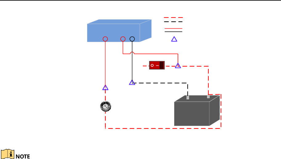
ACC DC IN
+-
Automobile Ignition Switch
Device
Automobile
Battery
Automobile Power System
Wiring of Device
Point of Connection
Positive Pole
Negative Pole
Automobile Power Switch
Figure 2-17 Shutdown Delay
Please contact the automobile manufacturer for the connection information of
starting switch.
The automobile ignition switch, also called car key, controls the startup and
shutdown of your automobile. Most of automobiles adopt positive pole ignition
switch currently.
The normal automobile power refers to the main power of the automobile power
supply system. After the automobile is off, the normal automobile power still
provides direct-current source for the other devices inside and generally a main
switch is used to turn on/off it.
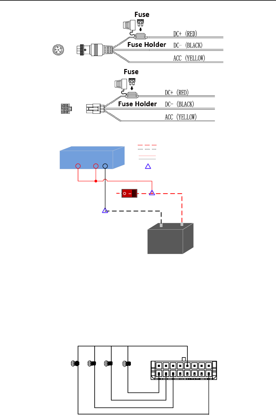
2.6.2 Scheduled Shutdown
Step 1 Connect the “DC IN +” and “KEY +” of the device to the positive pole of automobile
batteries.
Step 2 Connect the “DC IN -” and “KEY -” of the device to the negative pole of automobile
batteries.
Step 3 Place the fuse into the fuse holder.
What to do next: For detailed time settings of time-delay shutdown, see 16.1 Enable
Scheduled Startup/Shutdown.
Mobile Network Video Recorder User Manual
21
Figure 2-18 Install Fuse for Two Types of Power Supply
ACC DC IN
+-
Device
Automobile
Battery
Automobile Power Switch
Automobile Power System
Wiring of Device
Point of Connection
Negative Pole Positive Pole
Figure 2-19 Scheduled Shutdown
2.7 Alarm Input/Output Connection
2.7.1 Alarm Input Connection
The device adopts the high/low-level electrical signals triggering (high level: 6 to 36 VDC; low
level: 0 to 5 VDC) to realize alarm input. And in order to avoid error report caused by voltage
fluctuation, no alarm will be triggered by voltage ranging of 5 to 6 VDC.
Alarm 1
IO
Alarm 2
Alarm 3
Alarm 4
1
2
15
16
Figure 2-20 Alarm Input Connection
Mobile Network Video Recorder User Manual
22
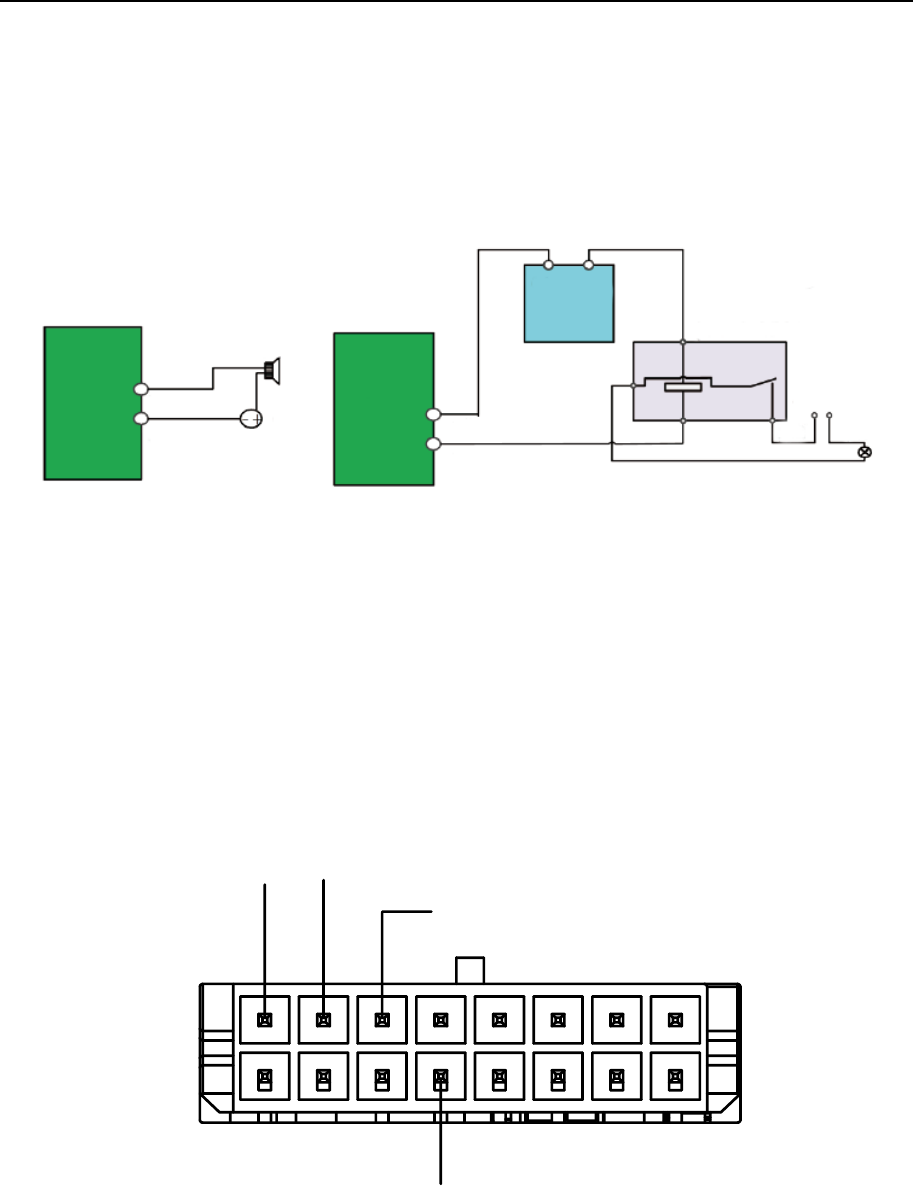
2.7.2 Alarm Output Connection
Follow the figure bellow to wire alarm output.
n and n# are a pair of alarm output. You can connect them with a relay alarm device. When
the voltage of connected alarm device exceeds the valid alarm output range, you need to
connect a relay to protect alarm output.
Relay
Output
n
n#
Load
GND Power
Output JQC-3FG
Relay
(10 A/250 VAC)
~ 220 VAC
NeutralLive
Relay
Output n#
n
Alarm Powered by Direct Current Alarm Powered by Alternating Current
Figure 2-21 Alarm Output Connection
2.8 Sensor-in Wiring
Step 1 Connect the delivered extension cable to I/O interface.
Step 2 Connect the automobile braking, reversing, left-turn, and right-turn signals to sensor-in
interface.
IO
Braking
Reversing
1
2
15
16
Left-turn Right-turn
Figure 2-22 Sensor-in Wiring
2.9 Power-on
Turn on the power supply after all the above installations are finished.

Mobile Network Video Recorder User Manual
24
Chapter 3 Start Up Device
3.1 Startup
Before you start:
Install the HDD. Refer to 2.1 Environment for details.
Connect the cables and modules correctly. Refer to Chapter 2 Installation and
Connections for details.
Step 1 Insert the key into the dummy HDD lock.
Step 2 Rotate it clockwise to ON status.
Do not perform any operations during the startup process.
The startup process takes about 1 minute. The system enters the live view interface
after startup.
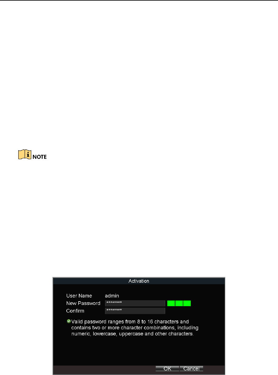
3.2 Activation
Purpose:
For the first-time access, you need to activate the device by setting an admin password. No
operation is allowed before activation.
Step 1 Enter the same password in the text field of New Password and Confirm.
Figure 3-1 Set Admin Password

Mobile Network Video Recorder User Manual
25
STRONG PASSWORD RECOMMENDED–We highly recommend you create a strong password
of your own choosing (Using a minimum of 8 characters, including at least three of the
following categories: upper case letters, lower case letters, numbers, and special characters.)
in order to increase the security of your product. And we recommend you reset your
password regularly, especially in the high security system, resetting the password monthly or
weekly can better protect your product.
Step 2 Click OK to save the password and activate the device.
For the old version device, if you upgrade it to the new version, a dialog box will pop up
once the device starts up. You can click YES and follow the wizard to set a strong password.
Mobile Network Video Recorder User Manual
26
Chapter 4 Network
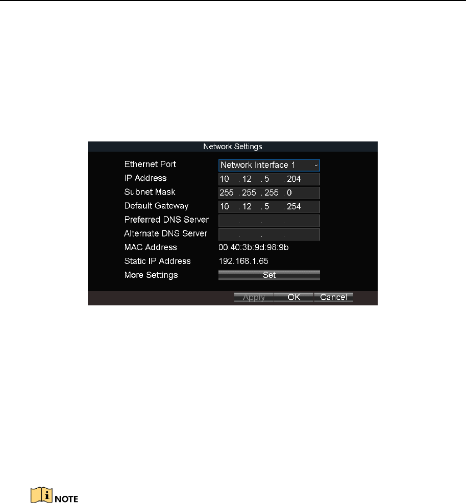
4.1 Set Local Network
Step 1 Go to Menu > Basic Settings > Network.
Figure 4-1 Local Network Settings
Step 2 Select Ethernet Port to configure.
Network Interface 1: The network interface in front panel.
Network Interface 2: The network interface in rear panel.
Step 3 Enter the device IP Address, Subnet Mask, Default Gateway, DNS Server Address, and
Download Server IP.
Step 4 Optionally, click Set of More Settings to enable/disable LAN Sharing.
LAN Sharing: Enable the function to share 3G/4G network to network interface.
The IP address of the device should be unique in the network and the default value is
192.168.1.64.
Step 5 Click OK.
4.2 Connect Wireless Network
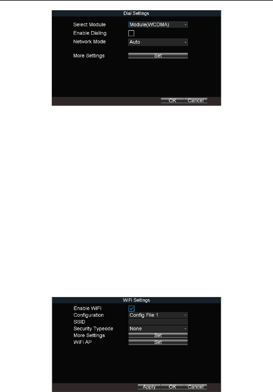
4.2.1 3G/4G Dialing
Before you start:
Install a 3G/4G SIM card on the device. Refer to 2.3 Install SIM Card for details.
Step 1 Go to Menu > Basic Settings > Dial.
Mobile Network Video Recorder User Manual
27
Figure 4-2 Dialing Settings
Step 2 Check Enable Dialing.
Step 3 Configure the 3G/4G VPDN (Virtual Private Dialup Network) settings. Please consult
the local operator for the network parameters of the VPDN.
1) Click Set of More Settings.
2) Select Bearing Mode.
3) Enter APN (Access Point Name), Dial Number, User Name, and Password.
4) Select Verification Protocol.
5) Click OK.
Step 4 Click OK and reboot the device to activate the new settings.
Step 5 Optionally, go to Menu > Status > Dial to view dialing status.
4.2.2 Set Wi-Fi
Purpose:
Connect the device to a Wi-Fi network and transmit the data via the Wi-Fi.
Step 1 Go to Menu > Basic Settings > WiFi.
Figure 4-3 Wi-Fi Settings
Step 2 Check Enable WiFi.
Mobile Network Video Recorder User Manual
28
Step 3 Select the Configuration file. 5 configuration files are available and only one SSID can
be set for each file.
Step 4 Select network SSID (Service Set Identifier), Security Type, Encryption Type, and Key.
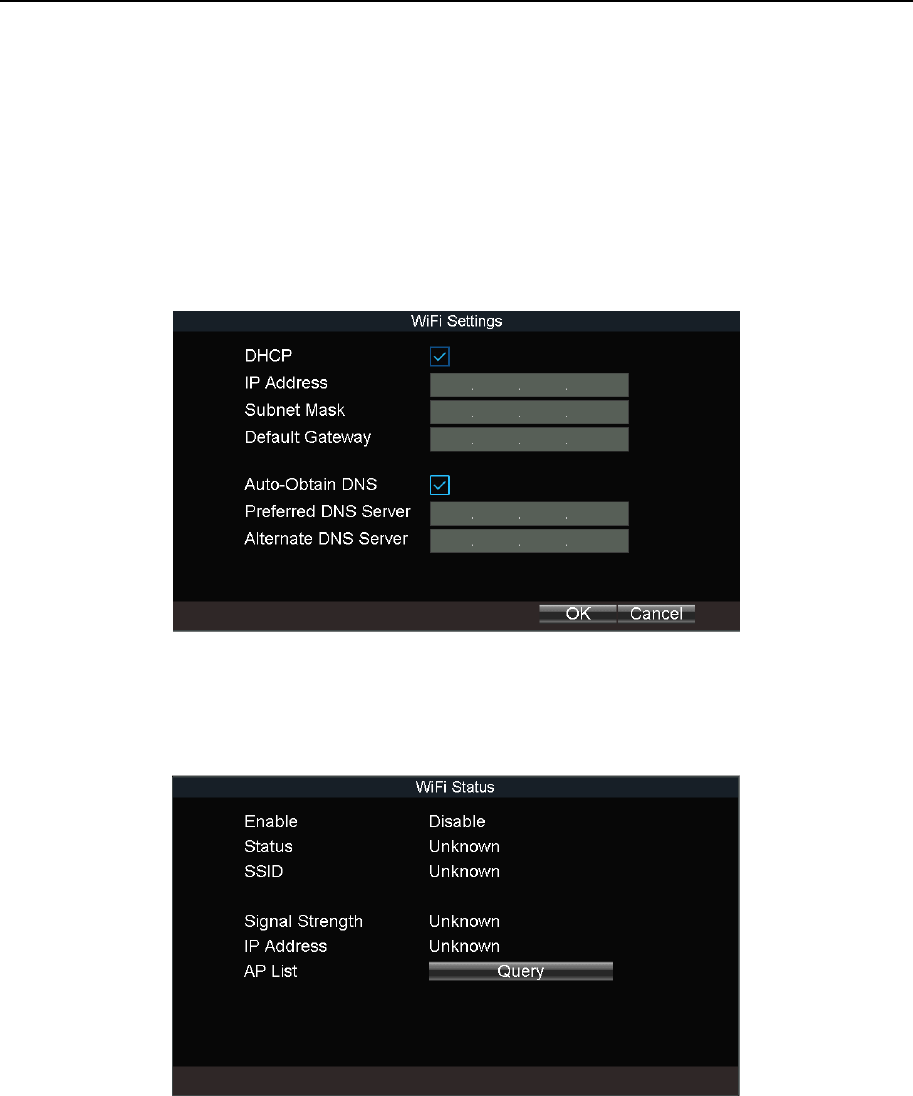
Step 5 Set the IP address and DNS server for Wi-Fi network.
1) Click Set of More Settings.
2) Configure IP address and DNS parameters.
3) Click OK.
Figure 4-4 IP & DNS Settings for Wi-Fi
Step 6 Click OK.
Step 7 Optionally, go to Menu > Status > WiFi to view the Wi-Fi status.
Figure 4-5 Wi-Fi Status Interface
4.2.3 Set Wi-Fi AP
Purpose:
Configure Wi-Fi access point settings.
Step 1 Go to Menu > Basic Settings > WiFi.
Mobile Network Video Recorder User Manual
29
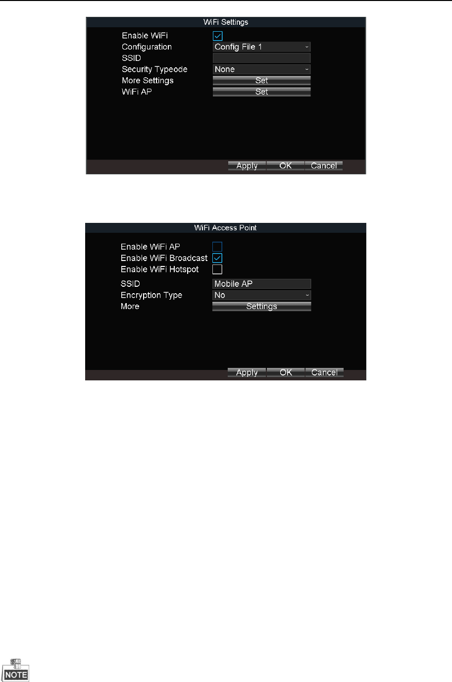
Figure 4-6 Wi-Fi Settings
Step 2 Click Set of WiFi AP
Figure 4-7 Wi-Fi Access Point Settings
Step 3 Check Enable WiFi AP and edit other parameters as required.
Enable WiFi AP: Once enabled, the device can work as a wireless router.
Enable WiFi Broadcast: Once enabled, other devices are able to detect the SSID of the
device.
Enable WiFi Hotspot: Enable it to share the device’s internet connection. Other devices
can access to internet via joining the hotspot.
Step 4 Click OK.
4.3 Firewall Settings
Purpose:
The device provides software-based firewall to protect the device against the threats from
the public network. A white list can be set, and only the trusted IP addresses on the white list
can access the device via the network.
192.0.0.xxx are set as the default trusted IP addresses.
Mobile Network Video Recorder User Manual
30
The IP address of the platform server to add the device is set as the trusted IP address.
Up to 16 IP addresses can be added on the white list.
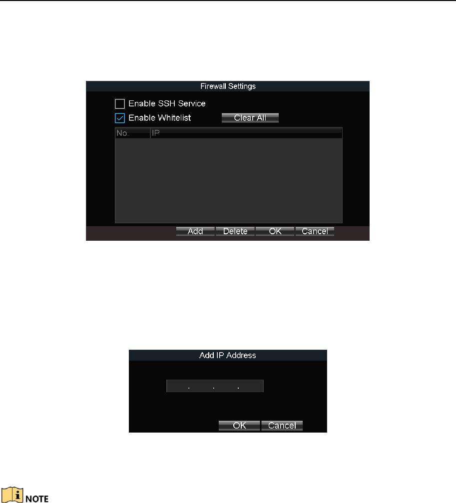
Step 1 Go to Menu > Other Settings > Firewall.
Figure 4-8 Firewall Settings
Step 2 Optionally, select Enable SSH Service to effectively prevent information leakage during
remote management.
Step 3 Click Add.
Step 4 Enter the trusted IP address and click OK.
Figure 4-9 Add IP Address
Step result: The trusted IP address will be added on the white list.
The configured whitelist will be cleared after you reboot the device.
Mobile Network Video Recorder User Manual
31
Chapter 5 IP Camera Management
Purpose:
Add IP cameras to the device. You can get the live view, record the video, and set the
parameters of the connected IP camera. If the device provides PoE function, you can connect
the PoE cameras to the device PoE interfaces.
5.1 Activate IP Camera
Purpose:
Before adding an IP camera, activate it by setting a password for it.
5.1.1 Auto Activation
Purpose:
Activate the IP camera by setting its password the same with the device password.
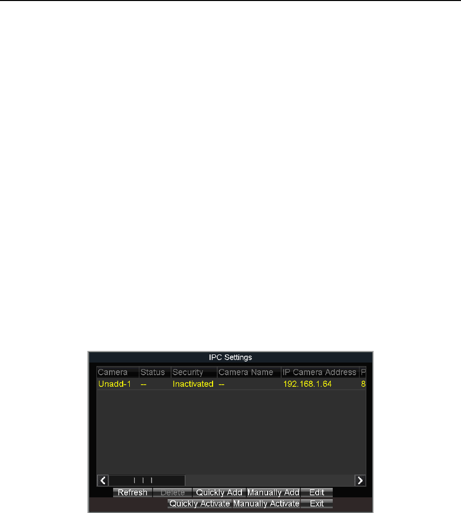
Step 1 Go to Menu > Other Settings > IPC Settings.
Figure 5-1 IPC Settings
Step 2 Select an inactivated IP camera.
Step 3 Click Quickly Activate. The IP camera password will be set as the same with the device
password.
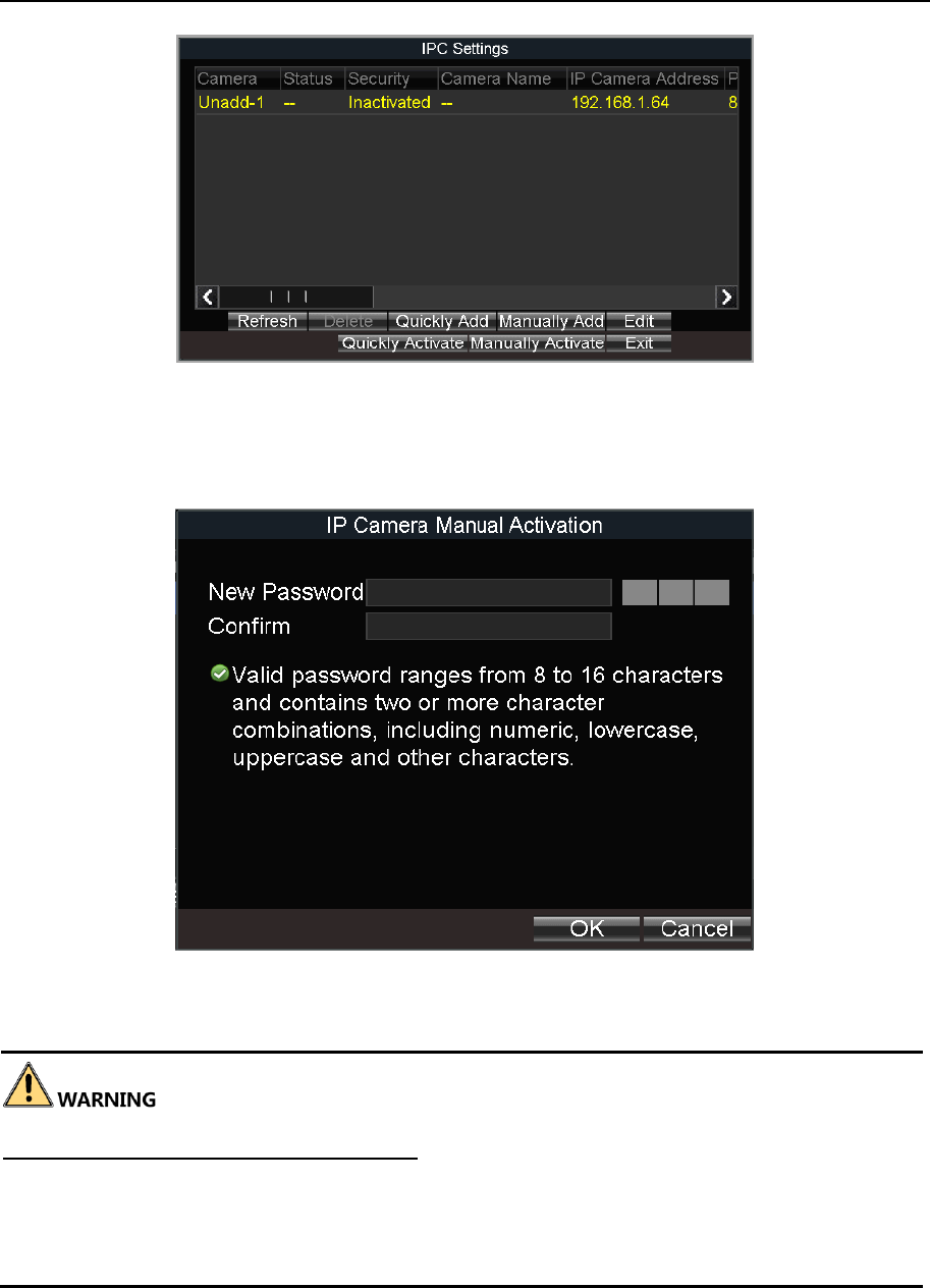
5.1.2 Manual Activation
Step 1 Go to Menu > Other Settings > IPC Settings.
Mobile Network Video Recorder User Manual
32
Figure 5-2 IPC Settings
Step 2 Select an inactivated IP camera.
Step 3 Click Manually Activate.
Figure 5-3 Activate IP Camera Manually
Step 4 Enter the same password in New Password and Confirm.
STRONG PASSWORD RECOMMENDED – We highly recommend you create a strong
password of your own choosing (Using a minimum of 8 characters, including at least three of
the following categories: upper case letters, lower case letters, numbers, and special
characters.) in order to increase the security of your product. And we recommend you reset
your password regularly, especially in the high security system, resetting the password
monthly or weekly can better protect your product.
Step 5 Click OK.
Mobile Network Video Recorder User Manual
33
5.2 Add IP Camera
Purpose:
You can add the online IP cameras. Ensure the network communication between the device
and IP camera is well.
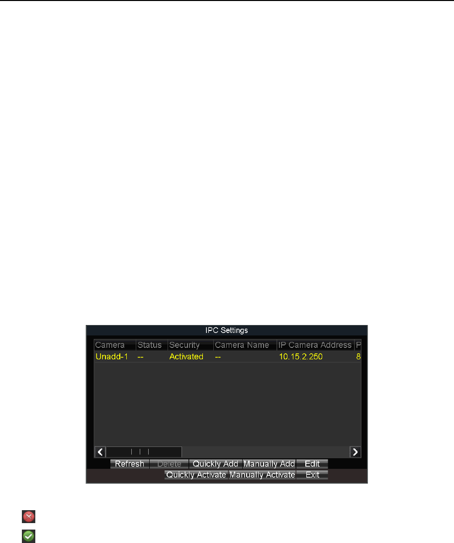
5.2.1 Quick Add
Purpose:
The online IP cameras in the same network segment with the device will be displayed on a
list. If the IP camera on the list has the same password with the device, you can quickly add
it.
Before you start:
Make sure the IP camera password is the same with the device.
Step 1 Go to Menu > Other Settings > IPC Settings.
Step 2 Select an online IP camera.
Step 3 Click Quickly Add.
Figure 5-4 Quick Add
: The IP camera is disconnected.
: The IP camera is connected.
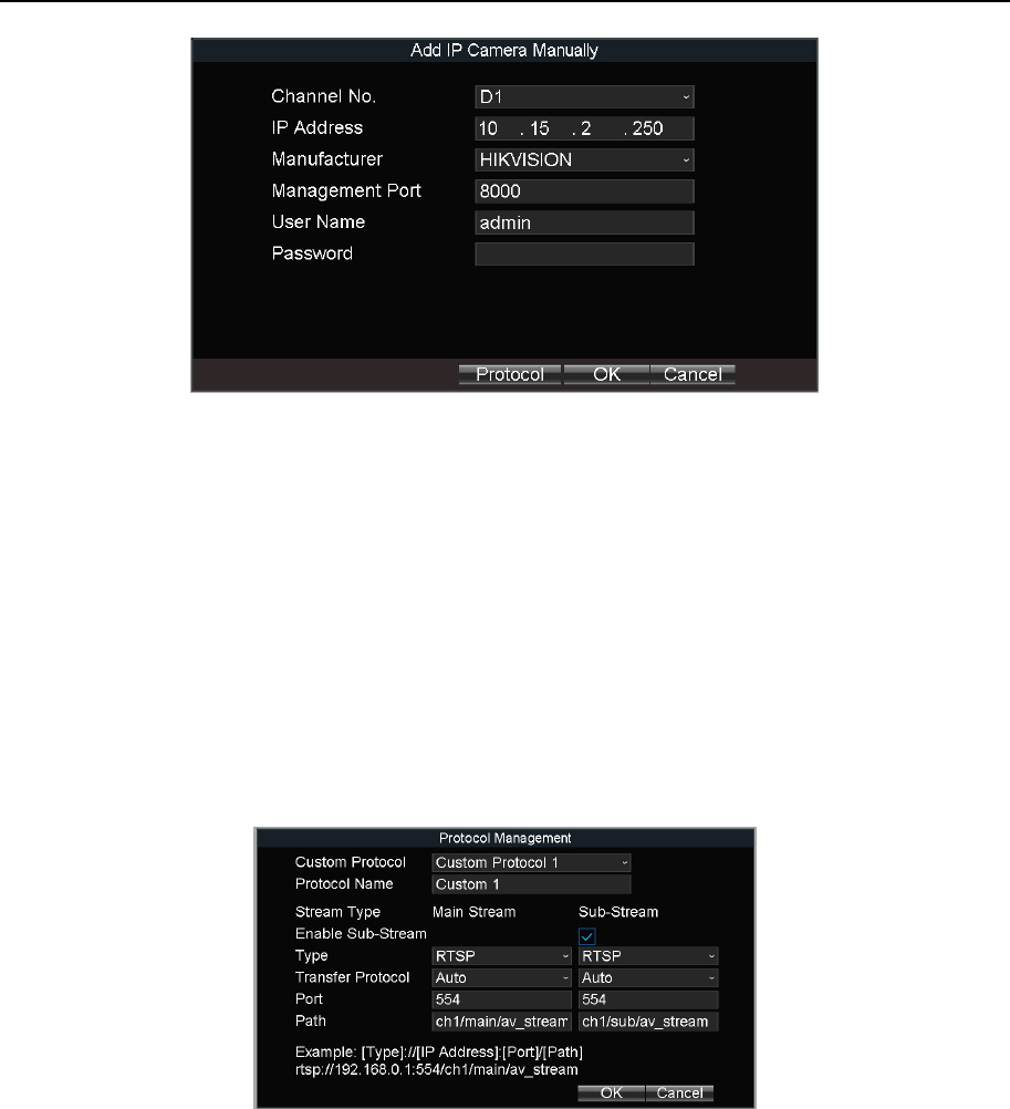
5.2.2 Manual Add
Step 1 Go to Menu > Other Settings > IPC Settings.
Step 2 Click Manually Add.
Step 3 Select the IP channel No. for the IP camera.
Step 4 Edit the required information, including the IP Address, Protocol, Port No., User Name,
and Password.
Step 5 Click OK.
Mobile Network Video Recorder User Manual
34
Figure 5-5 Manual Add
5.2.3 Edit Protocol
Purpose:
To connect the network cameras which are not configured with the standard protocols, you
can configure the customized protocols for them. The system provides 16 customized
protocols.
Step 1 Go to Menu > Other Settings > IPC Settings.
Step 2 Click Manually Add.
Step 3 Click Protocol.
Figure 5-6 Protocol
Step 4 Edit parameters as required.
Step 5 Click OK
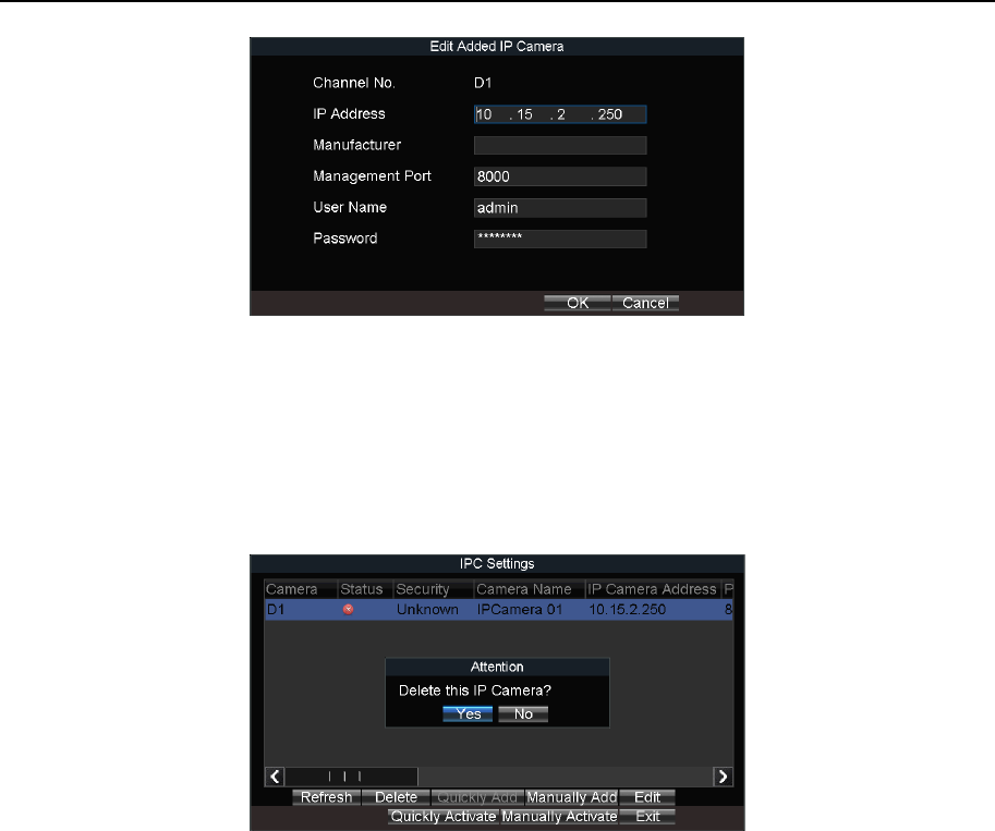
5.3 Edit IP Camera
Step 1 Select an added IP camera and click Edit.
Step 2 Edit the parameters.
Step 3 Enter Password. The password must be correct.
Step 4 Click OK.
Mobile Network Video Recorder User Manual
35
Figure 5-7 Edit IP Camera
5.4 Delete IP Camera
Step 1 Select an IP camera and click Delete.
Step 2 Click Yes on the pop-up dialog box.
Figure 5-8 Delete IP Camera
Mobile Network Video Recorder User Manual
36
Chapter 6 Camera Management
6.1 Basic Image Settings
6.1.1 Set OSD Parameters
Purpose:
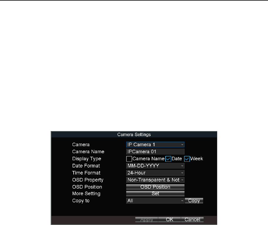
Configure the camera name, OSD (On Screen Display) settings, etc.
Step 1 Go to Menu > Other Settings > Camera.
Figure 6-1 Camera Settings
Step 2 Select Camera to configure.
Step 3 Edit parameters as your desire.
Step 4 Optionally, select the camera in Copy to dropdown list and click Copy to copy the
current settings to the selected camera.
Step 5 Click OK.
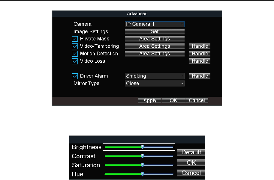
6.1.2 Set Image Parameters
Step 1 Go to Menu > Other Settings > Camera.
Step 2 Click Set of More Setting.
Mobile Network Video Recorder User Manual
37
Figure 6-2 More Setting
Step 3 Click Set of Image Settings.
Figure 6-3 Image Settings
Step 4 Edit the parameters.
Step 5 Click OK.
Step 6 Click OK in advanced settings interface.
Step 7 Click OK in camera settings interface.
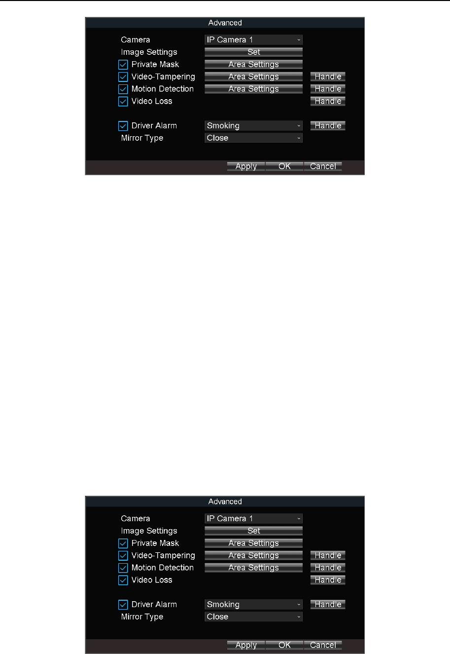
6.2 Set Privacy Mask
Purpose:
The privacy mask can be used to protect personal privacy by concealing parts of the image
from view or recording with a masked area.
Step 1 Go to Menu > Other Settings > Camera.
Mobile Network Video Recorder User Manual
38
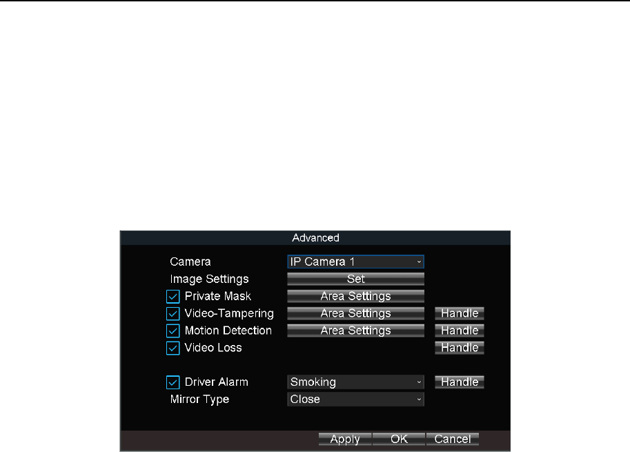
Figure 6-4 Advanced Settings
Step 2 Click Set of More Setting.
Step 3 Check Private Mask.
Step 4 Click Area Settings of Private Mask.
Step 5 Draw areas.
Step 6 Right click and select Exit.
Step 7 Click OK in Advanced settings interface.
Step 8 Click OK in Camera settings interface.
6.3 Set Mirror Type
Purpose:
Set the mirror type of the image as left/right, up/down, or center. The camera image will
change according to the selected mirror type.
Step 1 Go to Menu > Other Settings > Camera.
Figure 6-5 Advanced Settings
Step 2 Click Set of More Setting.

Mobile Network Video Recorder User Manual
39
Step 3 Select Mirror Type as required.
Step 4 Click OK in Advanced settings interface.
Step 5 Click OK in Camera settings interface.
Mobile Network Video Recorder User Manual
40
Chapter 7 Live View
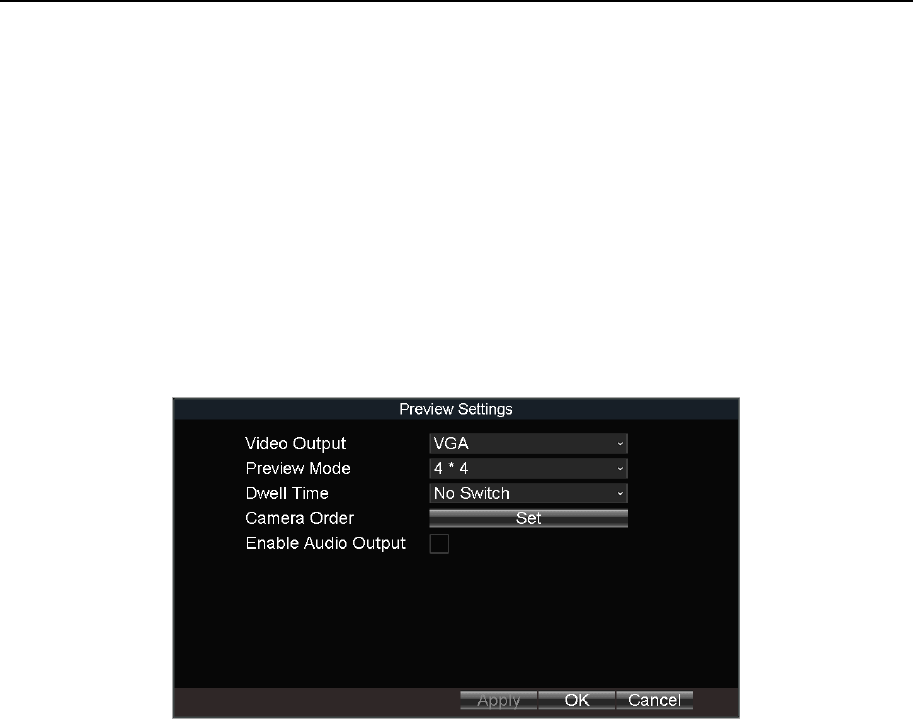
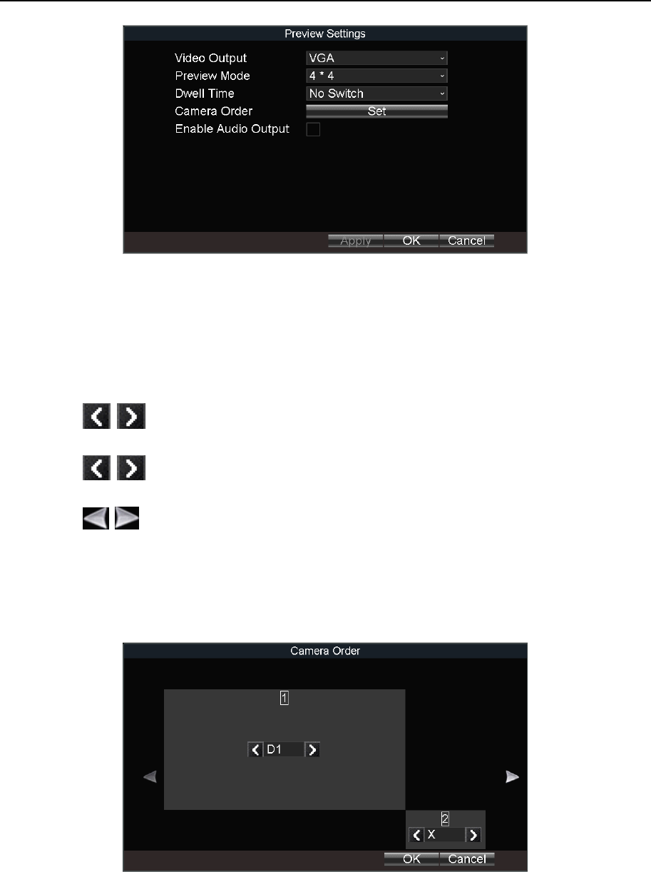
7.1 Preview Settings
Purpose:
Configure the dwell time of live view, set the camera order, enable/disable the audio preview,
etc.
Step 1 Go to Menu > Other Settings > Preview.
Figure 7-1 Preview Settings
Step 2 Select the Video Output according to the actual needs.
Step 3 Configure the Preview Mode, Dwell Time, and Enable Audio Output.
Preview Mode: Select the window division mode for live view.
Dwell Time: The switch interval of the live view screen. The screen will be switched to the
next one after the selected dwell time.
Enable Audio Output: Enable/disable audio output for the selected video output.
Step 4 Click OK.
7.2 Set Camera Order
Purpose:
Set the live display order for cameras.
Step 1 Go to Menu > Other Settings > Preview.
Mobile Network Video Recorder User Manual
41
Figure 7-2 Preview Settings
Step 2 Configure Preview Mode. We take the example of preview mode is 1+1 to describe the
following steps.
Step 3 Click Set of Camera Order.
Step 4 Click / of window-1 to select camera to display.
Step 5 Click / of window-2 to select camera to display.
Step 6 Click / to switch to next page.
Step 7 Repeat step 4 to 6 to configure camera order for other pages.
Step 8 Click OK.
Figure 7-3 Camera Order (1+1 Preview Mode)
Step 9 Click OK in Preview Settings interface.
Mobile Network Video Recorder User Manual
42
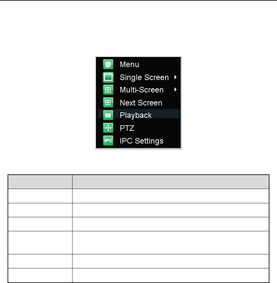
7.3 Right-Click Menu
Purpose:
In live view, right click to pop up right-click menu.
Figure 7-4 Right-Click Menu
Table 7-1 Item Description
7.4 PTZ Operation
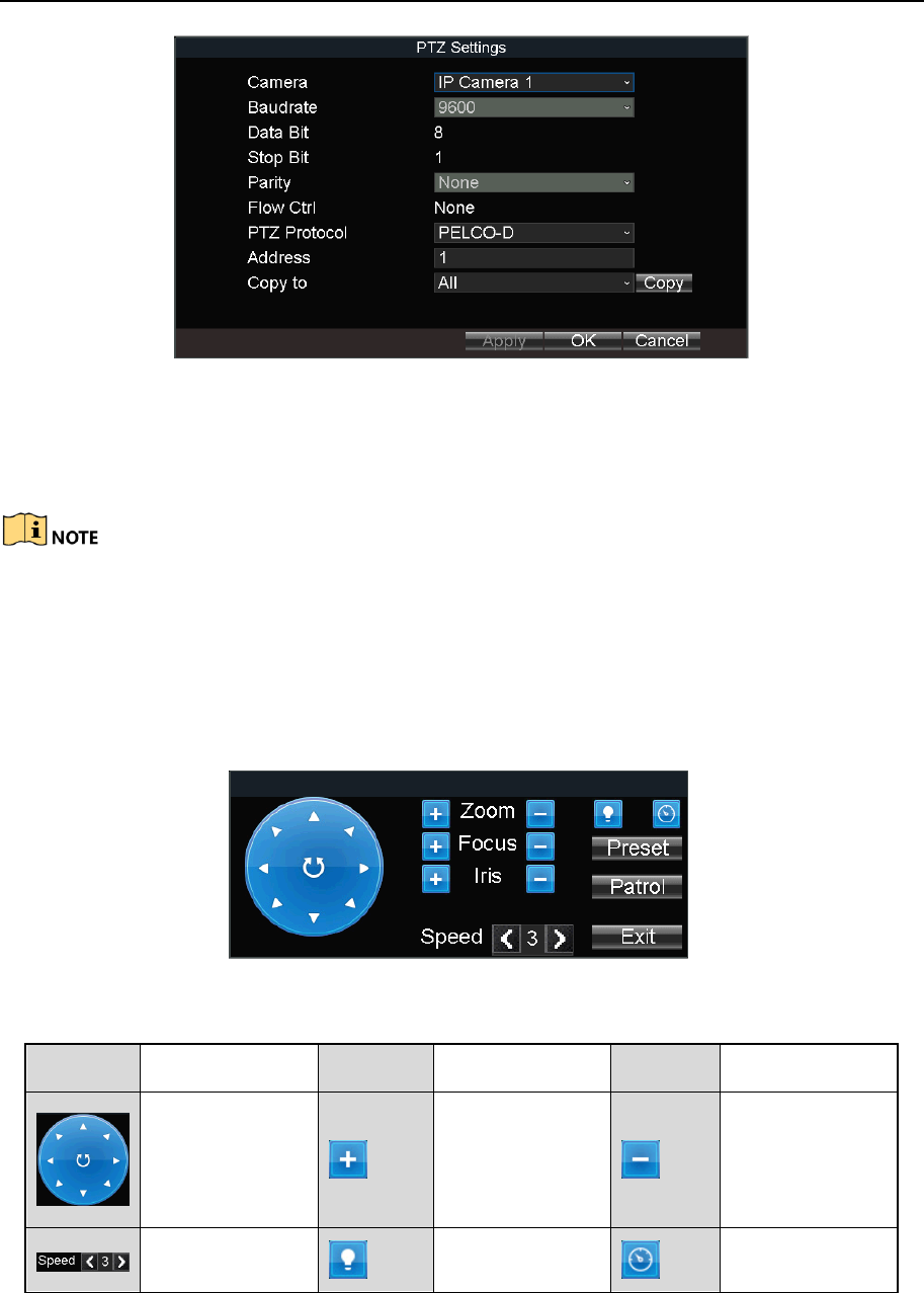
7.4.1 Configure PTZ Settings
Purpose:
Follow the procedure to set the parameters for PTZ. The configuration of the PTZ parameters
should be done before you control the PTZ camera.
Step 1 Go to Menu > Other Settings > PTZ.
Item
Description
Menu
Enter the main menu of the system by right clicking the mouse.
Multi-Screen
Adjust the screen layout by choosing from the dropdown list.
Next Screen
Switch to the next screen.
Playback
Enter the playback interface and start playing back the video of
the selected channel immediately.
PTZ
Click to pop up PTZ control panel.
IPC Settings
Click to enter network camera adding interface.
Mobile Network Video Recorder User Manual
43
Figure 7-5 PTZ Settings
Step 2 Select the Camera for PTZ settings.
Step 3 Configure the parameters of the PTZ camera.
All the parameters should be exactly the same with those of the PTZ camera.
Step 4 Click OK.
7.4.2 PTZ Control Panel
In live view interface, right click a PTZ camera and click PTZ on right-click menu.
Figure 7-6 PTZ Control Panel
Table 7-2 Description of PTZ Control Panel
Icon
Description
Icon
Description
Icon
Description
Direction
buttons and
the auto-cycle
button
Zoom+, Focus+,
Iris+
Zoom-, Focus-,
Iris-
Moving speed
Light on/off
Wiper on/off
Mobile Network Video Recorder User Manual
44
Chapter 8 Storage
8.1 Storage Settings
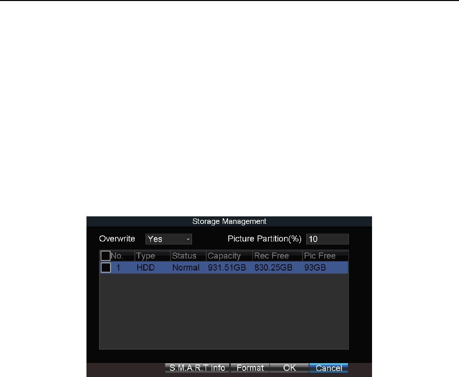
8.1.1 Format HDD
Purpose:
A newly installed hard disk drive (HDD) must be initialized before it can be used.
Step 1 Go to Menu > Storage.
Figure 8-1 Storage Management
Step 2 Check the HDD to format.
Step 3 Click Format.
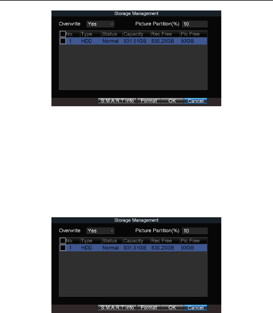
8.1.2 Configure Overwrite
Purpose:
The overwrite function is enabled by default. If the function is disabled, the recording and
capturing will be stopped when the storage device is full.
Step 1 Go to Menu > Storage.
Mobile Network Video Recorder User Manual
45
Figure 8-2 Storage Management
Step 2 Select Overwrite as Yes or No.
Step 3 Click OK.
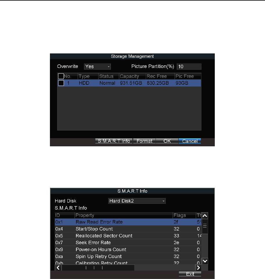
8.1.3 Configure Picture Partition
Purpose:
Specify the percentage of picture partition among the whole storage capacity. You can start
capturing in eHome platform.
Step 1 Go to Menu > Storage.
Figure 8-3 Storage Management
Step 2 Enter Picture Partition.
Step 3 Click Yes on popup message box to format HDD.
Step 4 Click OK to confirm the operation.
Step 5 Click OK.
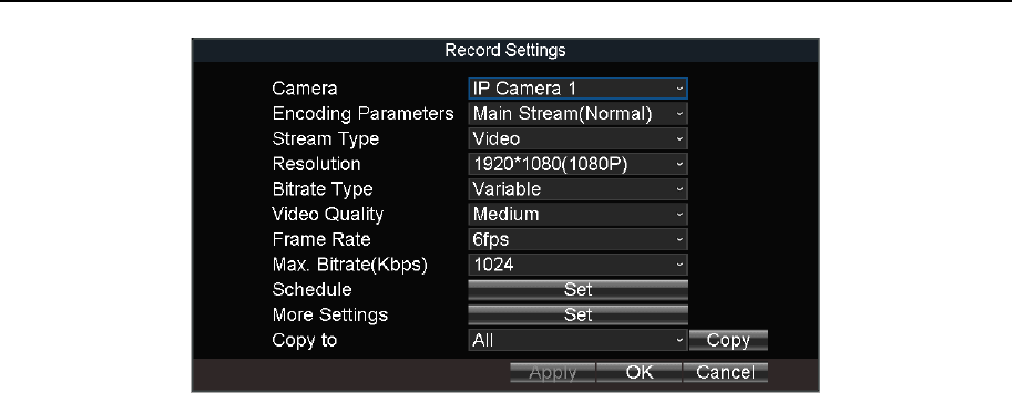
8.1.4 View S.M.A.R.T. Information
Purpose:
Mobile Network Video Recorder User Manual
46
The S.M.A.R.T. (Self-Monitoring, Analysis and Reporting Technology) is a monitoring system
for HDD to detect and report on various indicators of reliability in the hopes of anticipating
failures.
Step 1 Go to Menu > Storage.
Figure 8-4 Storage Management
Step 2 Select an HDD.
Step 3 Click S.M.A.R.T. Info.
Figure 8-5 S.M.A.R.T. Information
8.2 Recording Settings
8.2.1 Configure Record Settings
Purpose:
Configure the transmission stream type, the resolution, frame rate, etc.
Step 1 Go to Menu > Basic Settings > Record.
Mobile Network Video Recorder User Manual
47
Figure 8-6 Record Settings
Step 2 Select Camera.
Step 3 Configure the image parameters.
Encoding Parameters
Main Stream (Normal): Used for continuous recording.
Main Stream (Event): Used for event recording.
Sub-Stream: Used for network transmission.
Stream Type
Video and Video & Audio are selectable.
Bitrate Type
Variable and Constant are selectable.
Variable: The video quality is configurable.
Constant: The video quality is set as Medium and cannot be edited.
Video Quality
Bitrate type is variable, you can set the video quality as Highest, Higher, Medium, Low,
Lower, or Lowest.
Frame Rate
Frame rate refers to the frequency of the image frame after compression. With other
parameters constant, reduce the video frame rate, and you can lower the maximum
bitrate to some extent.
Max. Bitrate(Kbps)
Select the fixed value provided by the system or customize the maximum bitrate as
desired.
Step 4 Edit recording schedule. For details, refer to 8.2.5 Configure Schedule.
Step 5 Click Set of More Settings to configure the pre-record and post-record time.
Pre-Record: Normally used for the event (motion or alarm) triggered record, when you
want to record before the event happens. For example, when an alarm occurs at 10:00, if
the pre-record time is set as 5 seconds, the camera records the alarm at 9:59:55.
Mobile Network Video Recorder User Manual
48
Post-Record: After the event finished, the video can also be recorded for a certain time.
For example, when an alarm ends at 11:00, if the post-record time is set as 5 seconds,
the camera records till 11:00:05.
Step 6 Click OK.
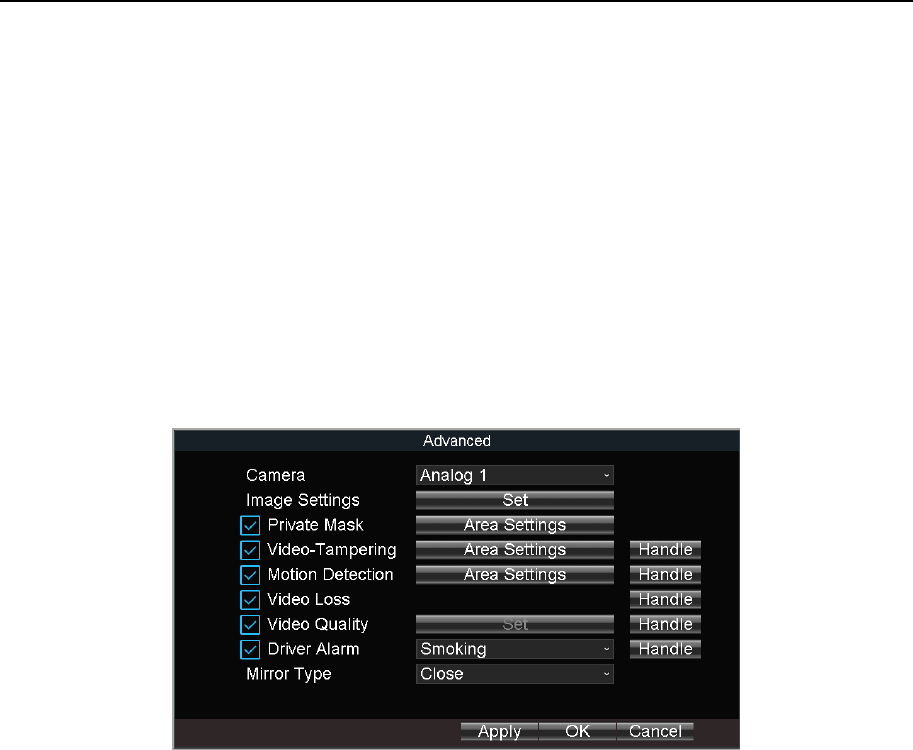
8.2.2 Configure Motion Detection Recording
Purpose:
In the motion detection recording, once a motion event occurs, the device starts to record.
Step 1 Go to Menu > Other Settings > Camera.
Step 2 Click Set of More Setting.
Figure 8-7 Motion Detection Settings
Step 3 Check Motion Detection.
Step 4 Click Area Settings of Motion Detection.
Step 5 Edit area settings. For details, refer to 12.11 Configure Detection Area.
Step 6 Set the camera to trigger motion detection recording.
1) Click Handle of Motion Detection.
2) Click Set of Triggered Alarm.
3) Check cameras to trigger recording and click OK.
4) Click OK.
Step 7 Click OK.
Step 8 Set motion detection recording schedule. For details, refer to 8.2.5 Configure Schedule.
Recording type must be alarm, motion|alarm, or motion&alarm.
8.2.3 Configure Alarm Triggered Recording
Purpose:
Follow the procedure to configure alarm triggered recording.
Mobile Network Video Recorder User Manual
49
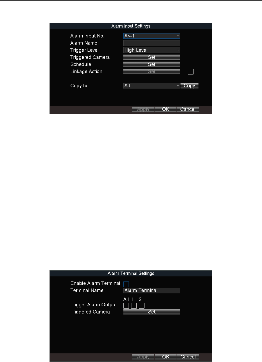
Step 1 Go to Menu > Other Settings > Alarm In.
Figure 8-8 Alarm Input Settings
Step 2 Click Set of Triggered Camera to select the alarm triggered recording channel.
Step 3 Click OK.
Step 4 Enter the record settings interface to set alarm triggered recording schedule. Refer to
8.2.5 Configure Schedule for record settings. Recording type must be alarm, motion |
alarm, or motion & alarm.
8.2.4 Configure Alarm Terminal
Before you start:
Install an alarm terminal. For details, refer to alarm terminal user manual.
The RS-232 serial port should be used in the way of transparent channel and the baud
rate should be set as 9600.
Step 1 Go to Menu > Other Settings > Alarm Terminal.
Figure 8-9 Alarm Terminal
Step 2 Check Enable Alarm Terminal.
Step 3 Edit Terminal Name.
Mobile Network Video Recorder User Manual
50
Step 4 Select Set of Triggered Camera to set the alarm triggered recording channel.
Step 5 Click OK.
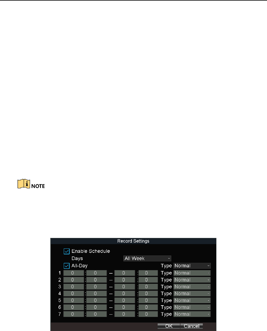
8.2.5 Configure Schedule
Step 1 Go to Menu > Basic Settings > Record.
Step 2 Click Set of Schedule.
Step 3 Check Enable Schedule.
Step 4 Select the day from the dropdown list for settings.
Step 5 Configure all day schedule or custom schedule.
Check All Day to enable all-day recording, and then select the recording type from the
drop-down list.
Uncheck All Day, customize the time period for recording, and select the recording type
for each time period.
Step 6 Click OK.
5 recording types are selectable: Normal, Motion Detection, Alarm, Motion|Alarm, and
Motion&Alarm.
Up to 8 time periods can be set for each day and each of the time periods cannot be
overlapped.
Figure 8-10 Record Schedule Settings
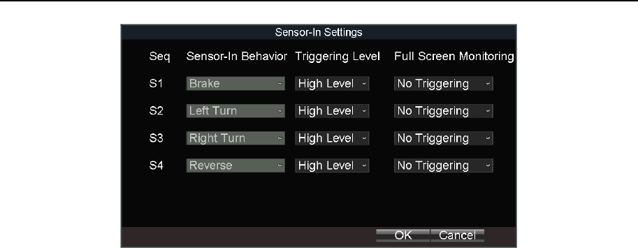
8.3 Sensor-in Settings
Purpose:
Sensor-in detects and records the driving information of automobile, including pedal braking,
turning left/right, reversing, etc.
Step 1 Go to Menu > Basic Settings > Sensor-In.
Mobile Network Video Recorder User Manual
51
Figure 8-11 Sensor-In Settings
Step 2 Set Triggering Level and Full Screen Monitoring for sensor-in.
Step 3 Click OK.
Mobile Network Video Recorder User Manual
52
Chapter 9 Playback
9.1 Instant Playback
Purpose:
You can search and play back the record files stored on the device instantly.
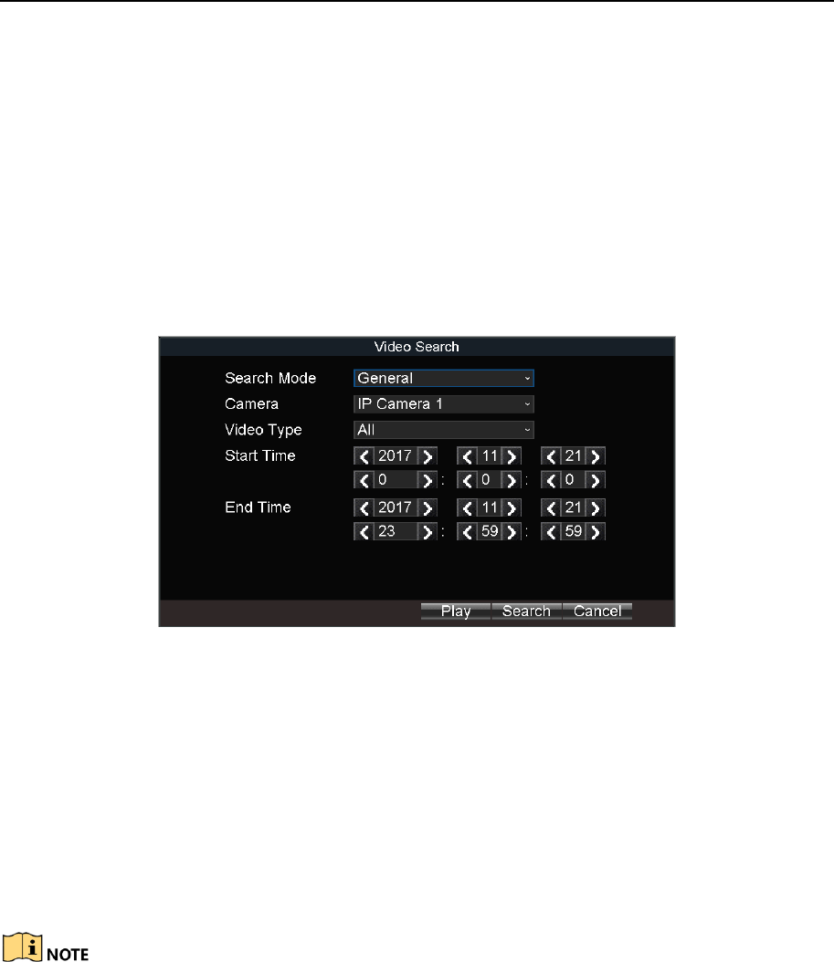
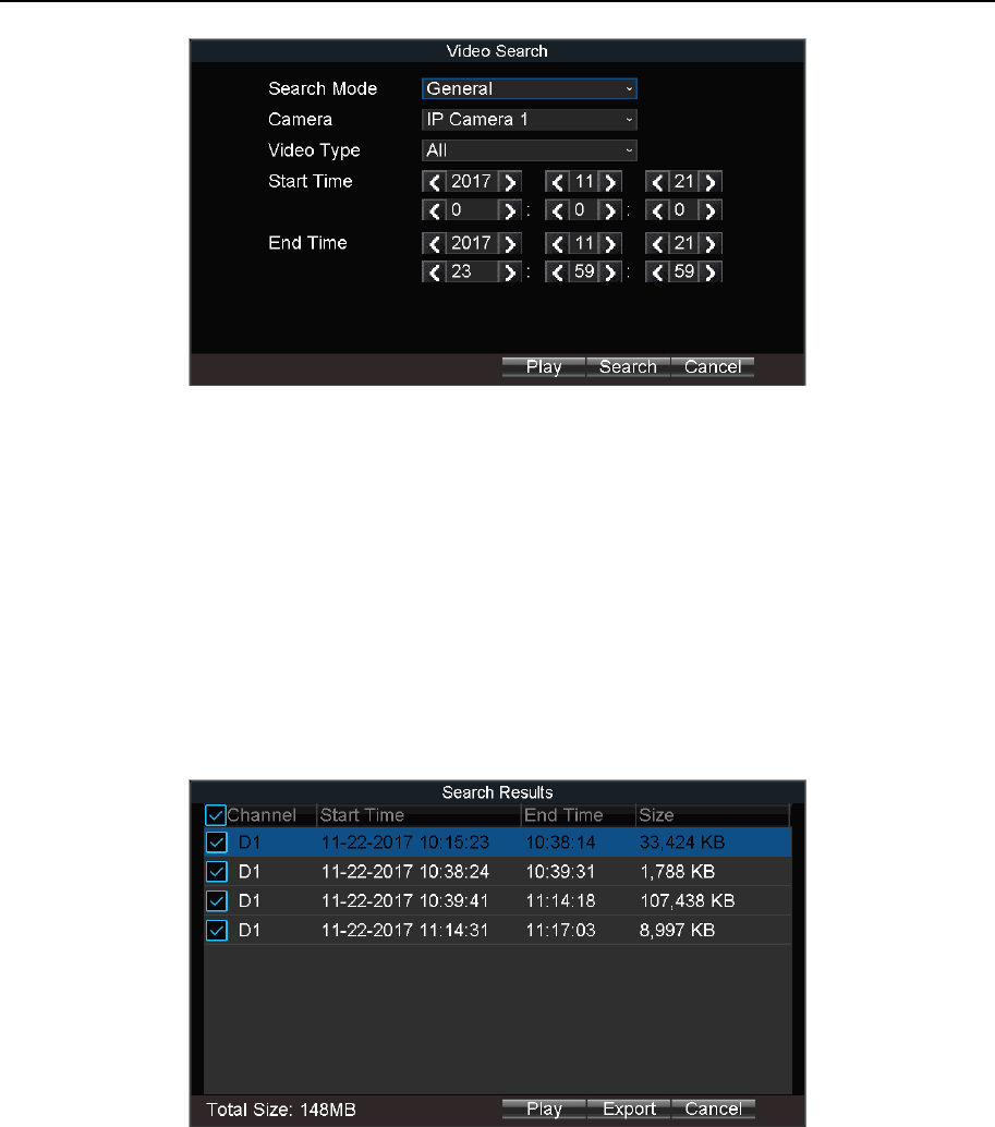
Step 1 Go to Menu > Video Search.
Figure 9-1 Video Search
Step 2 Select Search Mode as General. Only the general video supports instant playback.
General: Normal videos.
Step 3 Select Camera.
Step 4 Select Video Type.
Step 5 Specify Start Time and End Time.
Step 6 Click Play to play back the matched videos.
If more than 4,000 videos are found, the top 4,000 items have the priority to be played.
9.2 Play Video by File
Purpose:
You can search and play back the record files stored on the device.
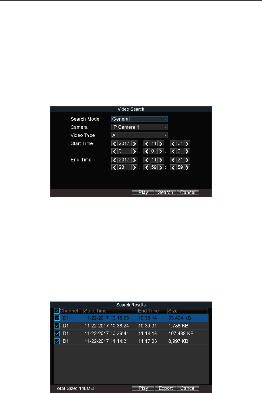
Step 1 Go to Menu > Video Search.
Mobile Network Video Recorder User Manual
53
Figure 9-2 Video Search
Step 2 Select Search Mode.
General: Normal videos.
Event: Motion detection, alarm, motion│alarm, and motion&alarm videos.
Step 3 Select Camera.
Step 4 Select Video Type.
Step 5 Specify Start Time and End Time.
Step 6 Click Search. The matched videos will be displayed.
Figure 9-3 Search Result
Step 7 Select a video and click Play.
Mobile Network Video Recorder User Manual
54
Chapter 10 Platform
10.1 Mobile Surveillance Platform
Purpose:
The device can be remotely accessed via mobile surveillance platform. For details of platform
configuration, you can refer to platform user manual.
When your device and mobile surveillance platform are not in the same network segment,
network priority: 3G/4G network > Wi-Fi > wired network.
Before you start:
Create the device ID on the mobile surveillance platform.
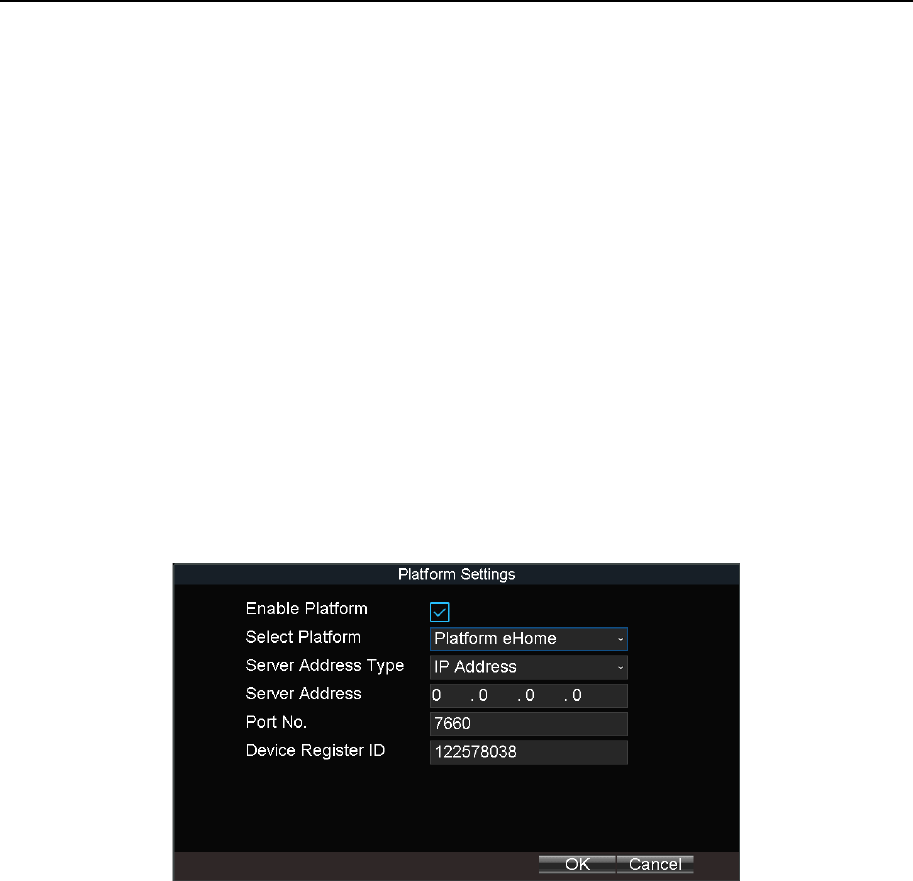
Step 1 Go to Menu > Basic Settings > Platform.
Figure 10-1 Platform Settings
Step 2 Check Platform Enable.
Step 3 Select Platform as eHome.
Step 4 Configure the following parameters.
Server Address Type: IP Address and Domain Name are selectable.
Server IP: Enter the static IP address of iVMS server.
Port No.: The default value for mobile surveillance platform is 7660.
Device Register ID: The ID of the device registered on the eHome platform. If you leave it
empty, device logs in to the platform with serial No.
Step 5 Click OK and reboot the device to activate the new settings.
Step 6 Optionally, go to Menu > Status > Platform to view the platform status.
Mobile Network Video Recorder User Manual
55
You can download mobile surveillance platform to your computer by visiting our
official website and going to Home > VMS > Support > Download > iVMS-5200
Mobile Surveillance.
Official website: http://www.hikvision.com/en/
You can download iVMS-5260M to your mobile phone by search it in app
store/google play or scan QR code below.
Figure 10-2 iOS
Figure 10-3 Android
10.2 Guarding Vision
Purpose:
The device can be remotely accessed via guarding vision platform.
Before you start:
Register the device in guarding vision platform. For detailed steps, refer to 10.3 Register
Device in Guarding Vision platform.
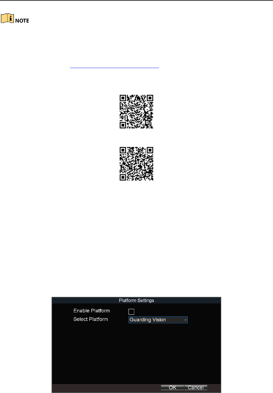
Step 1 Go to Menu > Basic Settings > Platform.
Figure 10-4 Platform Settings
Step 2 Check Enable Platform.

Mobile Network Video Recorder User Manual
56
Step 3 Select Platform as Guarding Vision.
Step 4 Click OK and reboot the device to activate the new settings.
Step 5 Optionally, go to Menu > Status > Platform to view the platform status.
10.3 Register Device in Guarding Vision platform
Step 1 Access Guarding Vision platform.
For computer user: dev.guardingvision.com.
For mobile phone user: download Guarding Vision app.
Step 2 Log in the platform.
Step 3 Register device by adding the device serial number and verification code.
Mobile Network Video Recorder User Manual
57
Chapter 11 Backup
11.1 Manual Backup
Purpose:
Back up the videos stored on the device.
Step 1 Go to Menu > Video Search.
Figure 11-1 Video Search
Step 2 Select Search Mode.
General: Normal videos.
Event: Motion detection, alarm, motion│alarm, motion&alarm videos.
Step 3 Select Camera.
Step 4 Select Video Type.
Step 5 Specify Start Time and End Time.
Step 6 Click Search. The matched videos will be displayed.
Figure 11-2 Search Result
Mobile Network Video Recorder User Manual
58
Step 7 Select the videos and click Export.
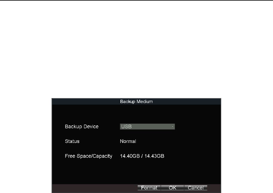
11.2 Format Backup Device
Purpose:
View the status and the free space/capacity of the connected backup device. And you can
also format the backup device.
Step 1 Go to Menu > Maintenance > Storage.
Figure 11-3 Backup Device
Step 2 Select Backup Device.
Step 3 View the Status and Free Space/Capacity of the backup device.
Step 4 Click Format to format the selected backup device.
Mobile Network Video Recorder User Manual
59
Chapter 12 Events and Alarms
12.1 Configure Motion Detection Alarm
Purpose:
When motion detection alarm is configured, once a motion event is detected, the device
starts to record and multiple linkage actions will be triggered.
Step 1 Go to Menu > Other Settings > Camera.
Step 2 Click Set of More Setting.
Figure 12-1 Motion Detection Settings
Step 3 Check Motion Detection.
Step 4 Set the area for motion detection. For detailed steps, refer to 12.11 Configure
Detection Area.
Step 5 Set the arming schedule and alarm linkage actions. For detailed steps, refer to 12.10
Configure Arming Schedule and Linkage Actions.
Step 6 Click OK.
12.2 Configure Alarm Input
Purpose:
Configure the settings for alarm input, including trigger level, arming schedule and alarm
linkage actions, etc.
Step 1 Go to Menu > Other Settings > Alarm In.
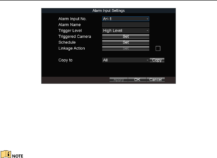
Mobile Network Video Recorder User Manual
60
Figure 12-2 Alarm Input Settings
Step 2 Select Alarm Input No.
Step 3 Enter Alarm Name.
Step 4 Select Trigger Level.
High level: 6 to 36 VDC.
Low level: 0 to 5 VDC.
In order to avoid error caused by voltage fluctuation, no alarm will be triggered by voltage
ranging from 5 VDC to 6 VDC.
Step 5 Click Set of Schedule to set arming schedule. For detailed steps, refer to 12.10
Configure Arming Schedule and Linkage Actions.
Step 6 Check Linkage Action and click Set of Linkage Action to set the linkage actions. For
detailed steps, refer to 12.10 Configure Arming Schedule and Linkage Actions.
Step 7 Click OK.
12.3 Configure Alarm Output
Purpose:
Configure the arming schedule, alarm duration time and alarm name for alarm output.
Step 1 Go to Menu > Other Settings > Alarm Out.
Mobile Network Video Recorder User Manual
61
Figure 12-3 Alarm Output Settings
Step 2 Select Alarm Output No.
Step 3 Enter Alarm Name.
Step 4 Select Dwell Time.
Dwell Time: Alarm output will keep alarming for the dwell time.
Step 5 Click Set of Schedule to set the arming schedule for alarm outputs. For detailed steps,
refer to 12.10 Configure Arming Schedule and Linkage Actions.
Step 6 Click OK.
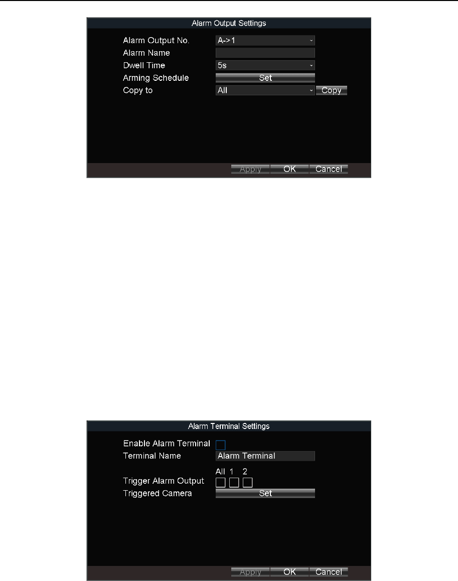
12.4 Configure Alarm Terminal
Step 1 Go to Menu > Other Settings > Alarm Terminal.
Figure 12-4 Alarm Terminal
Step 2 Check Enable Alarm Terminal.
Step 3 Edit the Terminal Name.
Step 4 Select the alarm outputs to trigger.
Step 5 Click OK.
Mobile Network Video Recorder User Manual
62
12.5 Configure Video Loss Alarm
Purpose:
When the device cannot receive video signal from the front-end devices, the video loss alarm
will be triggered. Linkage actions, including audible warning and alarm output, can be set to
respond.
Step 1 Go to Menu > Other Settings > Camera.
Step 2 Click Set of More Setting.
Figure 12-5 Video Loss
Step 3 Check Video Loss.
Step 4 Set arming schedule and linkage actions. For detailed steps, refer to 12.10 Configure
Arming Schedule and Linkage Actions.
Step 5 Click OK.
12.6 Configure Video Tampering Alarm
Purpose:
A tampering alarm is triggered when the camera is covered and the monitoring area cannot
be viewed. Linkage actions, including audible warning, alarm output, can be set to respond.
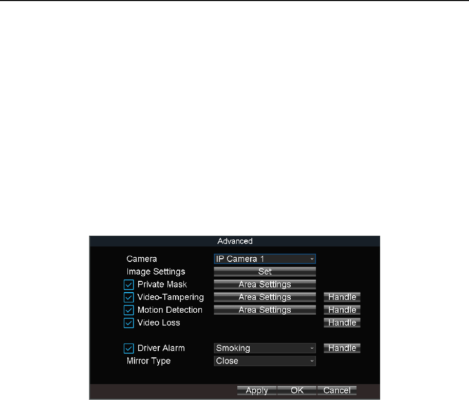
Step 1 Go to Menu > Other Settings > Camera.
Step 2 Click Set of More Setting.
Mobile Network Video Recorder User Manual
63
Figure 12-6 Video-Tampering
Step 3 Check Tamper-proof.
Step 4 Set area for video tampering detection. For detailed steps, refer to 12.11 Configure
Detection Area.
The video tampering alarm can be triggered only when the view of the camera is fully
covered.
Step 5 Set arming schedule and linkage actions. For detailed steps, refer to 12.10 Configure
Arming Schedule and Linkage Actions.
Step 6 Click OK.
12.7 Configure Exception Alarm
Purpose:
Configure alarms which are triggered by exceptions to take necessary actions in time.
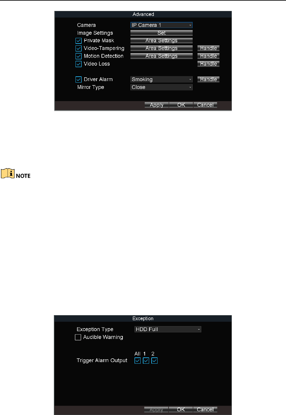
Step 1 Go to Menu > Other Settings > Exception.
Figure 12-7 Exception
Mobile Network Video Recorder User Manual
64
Step 2 Select Exception Type and set corresponding alarm linkage actions, including audible
warning and alarm output.
Step 3 Click OK.
Exception types include:
HDD Full: The HDD is full.
HDD Error: Writing HDD error, unformatted HDD, etc.
Network Disconnected: Network cable is disconnected.
IP Conflicted: Duplicated IP address.
Illegal Login: Incorrect user ID or password.
Video Input/Output Standard Mismatched: Input and output video standards do not
match.
Abnormal Recording: No space for saving recorded files.
12.8 Configure Satellite Positioning
Purpose:
The built-in GNSS module supports GPS (Global Positioning System), enabling device
positioning and speed limit alarm.
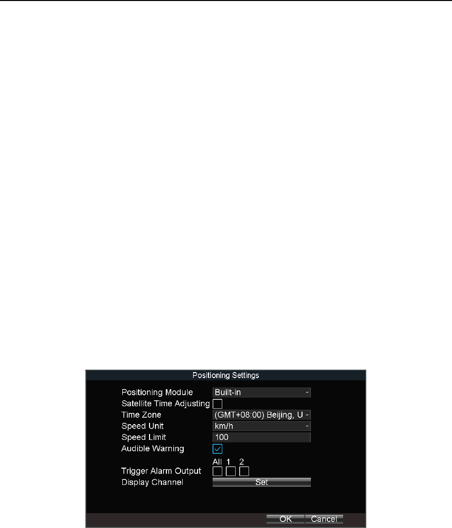
Step 1 Go to Menu > Basic Settings > Position.
Figure 12-8 Position
Step 2 Select Positioning Module.
Built-in: Obtain data from the satellite positioning module built in the device.
Display Terminal: Obtain data from display terminal.
Step 3 Check Satellite Time Adjusting and select your time zone.
Step 4 Select Speed Unit and input Speed Limit.
Step 5 Set the linkage action for speeding alarm, including Audible Warning and Alarm
Output.
Mobile Network Video Recorder User Manual
65
Step 6 Click Set of Display Channel and select display channels. The device positioning
information will be displayed on the selected channels.
Step 7 Click OK.
Step 8 Optionally, go to Menu > Status > Position to view positioning status.
12.9 Configure G-Sensor Alarm
Purpose:
G-Sensor detects and records acceleration information in 3-axial (X, Y, Z) directions.
Before you start:
Connect an external sensor to the device for obtaining and providing the acceleration speed
in 3-axial directions.
Step 1 Go to Menu > Basic Settings > G-Sensor.
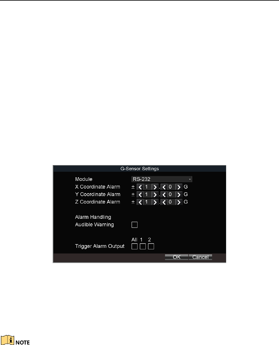
Figure 12-9 G-Sensor Settings
Step 2 Select G-sensor mode under Module.
RS-232: The G-sensor is connected to the device through RS-232 interface.
Built-in: The G-sensor is built in the device.
Step 3 Set the limit value for acceleration alarm in X, Y and Z directions.
X, Y and Z represent the direction of acceleration and the unit of alarm value is G (G=9.8
m/s2).
Step 4 Set the linkage actions for acceleration alarm, including Audible Warning and Alarm
Output.
Step 5 Click OK.
Step 6 Optionally, go to Menu > Status > G-sensor to view the G-sensor status.
Mobile Network Video Recorder User Manual
66
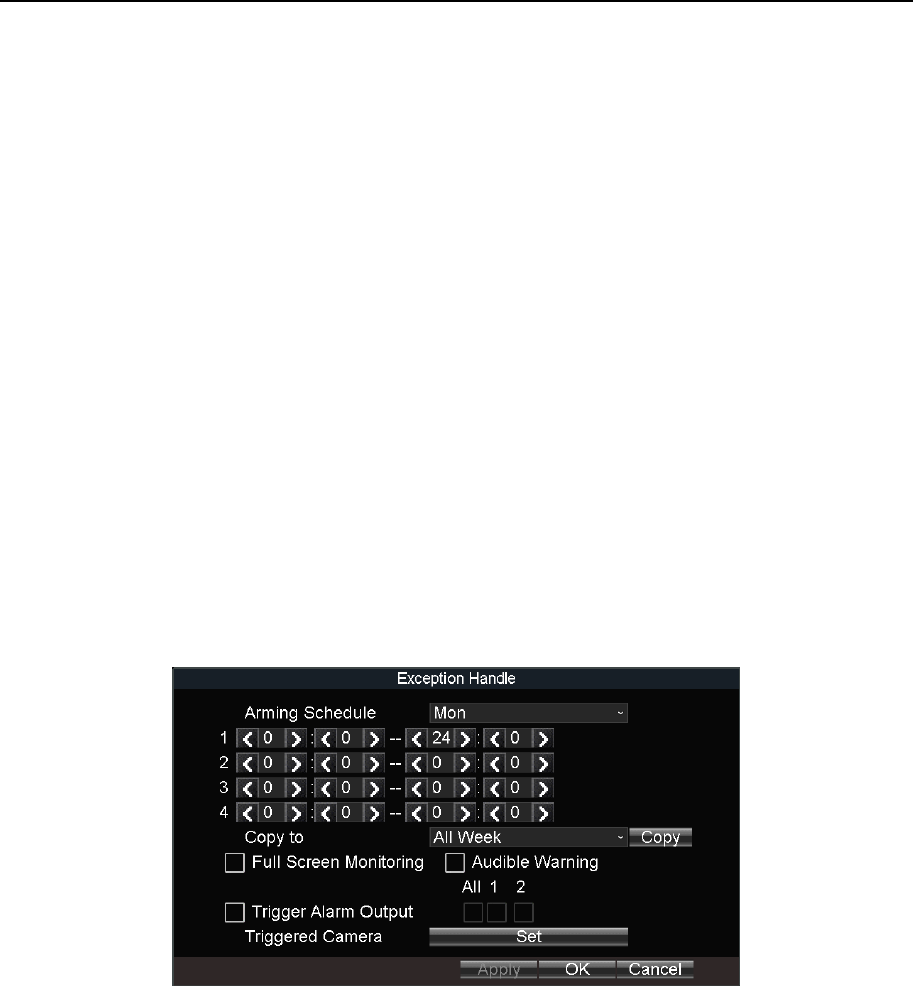
12.10 Configure Arming Schedule and Linkage Actions
Step 1 Click Handle to set the arming schedule and alarm linkage actions.
Step 2 Select the day from Arming Schedule dropdown list.
Step 3 Set the arming period for selected day.
Step 4 (Optional) Copy the current settings to other days in the week.
Step 5 Check to enable linkage actions.
Full Screen Monitoring
When an alarm is triggered, the local monitor displays the video image from the alarming
channel configured for full screen monitoring.
Audible Warning
Trigger an audible beep when an alarm is detected.
Trigger Alarm Output
Trigger an alarm output when an alarm is detected.
Step 6 Click OK.
Figure 12-10 Linkage Action
12.11 Configure Detection Area
Step 1 Click Area Settings.
Step 2 Drag to draw detection area.
Step 3 Optionally, right click to delete areas or set detection sensitivity.
Step 4 Right click and select Exit.
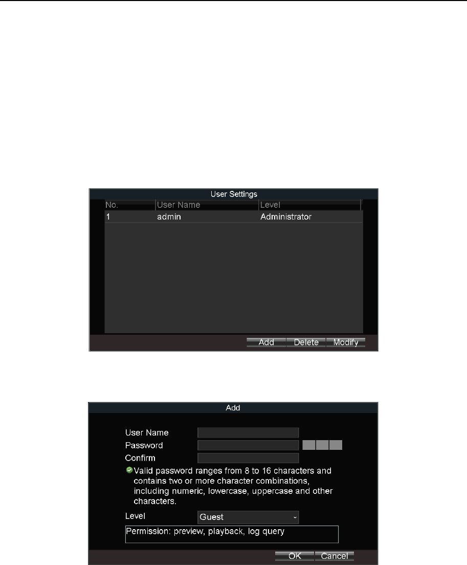
Mobile Network Video Recorder User Manual
67
Chapter 13 User Account Management
13.1 Add User
Purpose:
Add and delete users, and modify the password and permission of users.
Step 1 Go to Menu > Other Settings > User.
Figure 13-1 User Management
Step 2 Click Add.
Figure 13-2 Add User
Step 3 Enter User Name and Password and enter the same password in Confirm.
Step 4 Select the user permission level.
Operator: The operator has permissions for Preview, Playback, Backup, Log Search and
Parameters Settings.
Guest: The Guest has permissions for Preview, Playback, Backup and Log Search.
Step 5 Click OK.

Mobile Network Video Recorder User Manual
68
13.2 Delete User
Step 1 Go to Menu > Other Settings > User.
Step 2 Select a user and click Delete.
Step 3 Click Yes in confirmation message box.
13.3 Edit User
Step 1 Go to Menu > Other Settings > User.
Step 2 Select a user and click Modify.
Step 3 Edit parameters as required.
Step 4 Click OK.
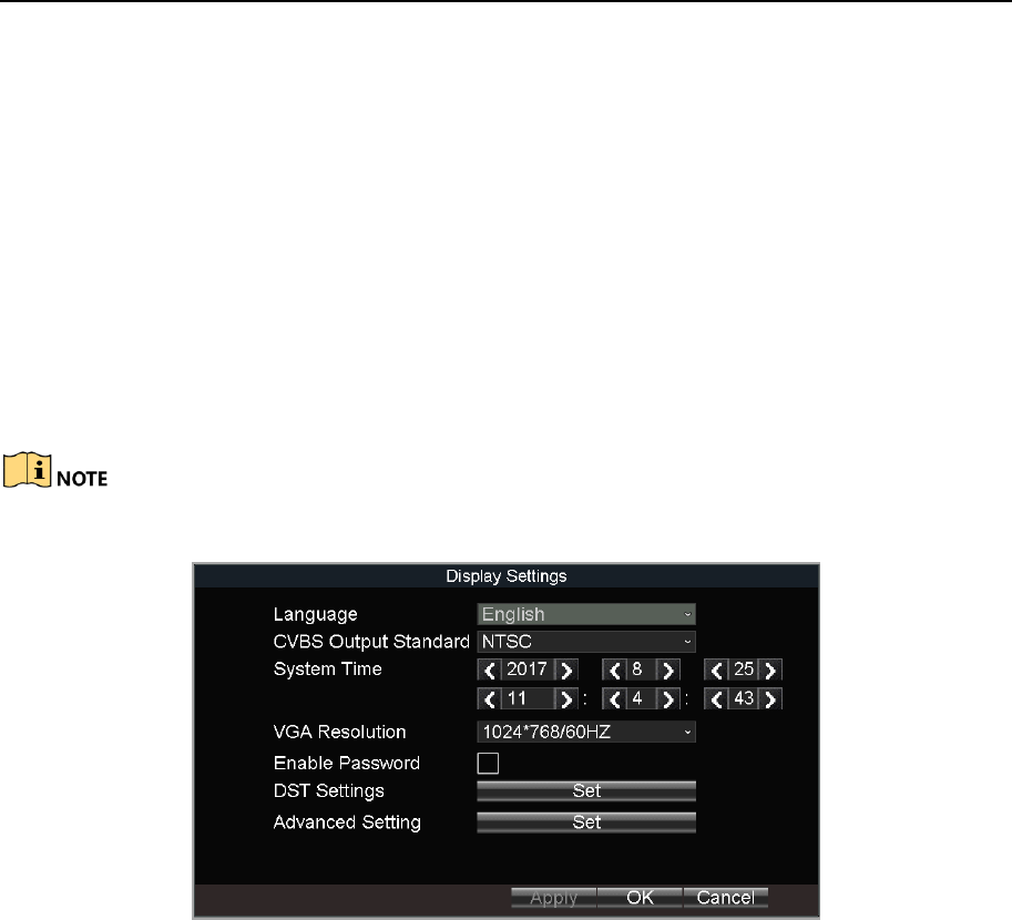
Mobile Network Video Recorder User Manual
69
Chapter 14 General System Configuration
14.1 Configure Basic Display Settings
Purpose:
Set system time, select CVBS output standard, enable password and configure DST settings,
etc.
Step 1 Go to Menu > Other Settings > Display.
The system language is set as English by default and is not editable.
Figure 14-1 Display Settings
Step 2 Edit parameters as required.
CVBS Output Standard: NTSC or PAL are selectable. Set it according to actual video input
standard.
System Time: Set it by adjusting year, month, day, hour, minute, and second.
VGA Resolution: Specify the VGA output resolution.
Enable Password: Check it to enable authentication before operations.
Step 3 Click OK.
14.2 Configure DST Settings
Purpose:
Configure DST (Daylight Saving Time) settings for the system.
Step 1 Go to Menu > Other Settings > Display.
Step 2 Click Set of DST Settings.
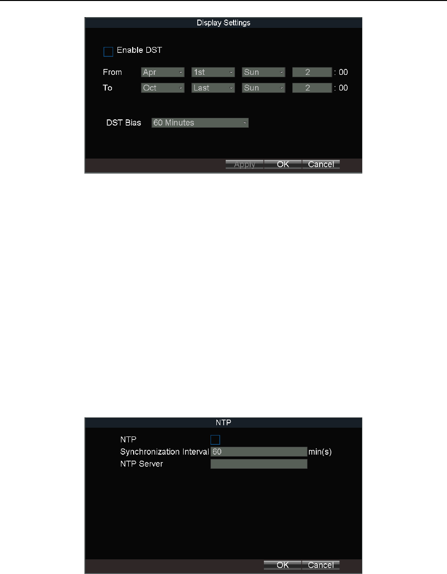
Mobile Network Video Recorder User Manual
70
Figure 14-2 DST Settings
Step 3 Check Enable DST.
Step 4 Set the start time and end time for DST.
Step 5 Select DST bias.
Step 6 Click OK in DST settings interface.
Step 7 Click OK in Display Settings.
14.3 Configure NTP
Step 1 Go to Menu > Basic Settings > Network.
Step 2 Click Set of More Settings.
Step 3 Click Set of NTP.
Figure 14-3 NTP Settings
Step 4 Check NTP to enable the function.
Step 5 Enter Synchronization Interval.
Step 6 Enter the IP address of NTP Server.
Step 7 Click OK in NTP settings interface.
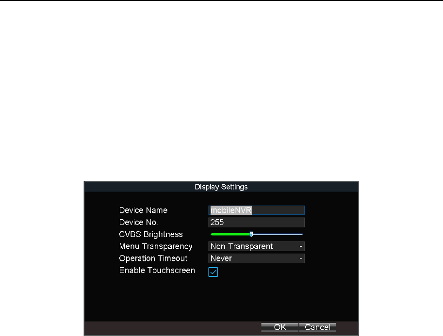
Mobile Network Video Recorder User Manual
71
Step 8 Click OK in network settings interface.
14.4 Configure Advanced Display Settings
Purpose:
Set the system time, select the CVBS output standard, enable the password, configure the
DST settings, etc.
Step 1 Go to Menu > Other Settings > Display.
Step 2 Click Set of Advanced Settings.
Figure 14-4 Advanced Settings
Step 3 Edit parameters as required.
Device Name: Enter the system name as desired.
Device No.: Edit the device No. for remote control. The device No. ranges from 1 to 255.
The default device No. is 255. It is not recommended to modify Device No. Otherwise,
you need to enter the Device No. on the remote control every time you use it.
CVBS Brightness: Adjust video output brightness.
Menu Transparency: The transparency proportion of the menu displayed on the live
view interface. You can set it as 1:3, 1:1, 3:1, or Non-transparent. The smaller the
proportion value is, the more transparent the menu is. When Non-transparent is
selected, only the menu is displayed on the page.
Operation Timeout: If no operation is performed after a specified period of time, live
view will be displayed automatically.
Enable Touchscreen: Enable/disable touchscreen. If the function is on, PTZ function is
unavailable.
Step 4 Click OK.
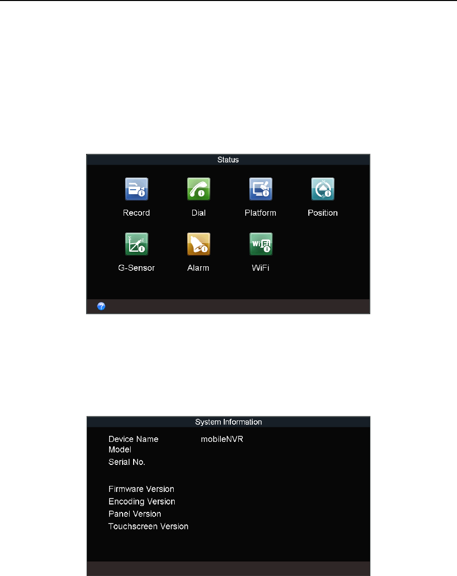
Mobile Network Video Recorder User Manual
72
Chapter 15 Maintenance
15.1 Check Status
Go to Menu > Status to view status of recording, 3G/4G, platform, satellite positioning,
G-Sensor, alarm, and WiFi.
Figure 15-1 Status
15.2 View System Information
Go to Menu > Maintenance > Information to view the device name, model, serial No.,
firmware version, encoding version, and panel version.
Figure 15-2 System Information
15.3 Upgrade the System
Purpose:
The device can be upgraded by local USB flash disk or remote FTP server.
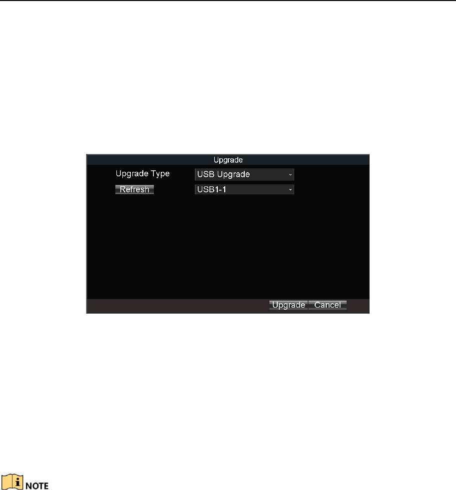
Mobile Network Video Recorder User Manual
73
15.3.1 Upgrade by Local USB Flash Disk
Before you start:
Connect the USB device that contains the upgrade firmware.
The upgrade firmware should be stored in the root directory of the USB device.
Step 1 Go to Menu > Maintenance > Upgrade.
Step 2 Select Upgrade Type as USB Upgrade.
Figure 15-3 Upgrade
Step 3 Click Upgrade to start upgrading and reboot the device to activate the new settings.
15.3.2 Upgrade by Remote FTP server
Before you start:
Ensure the network connection of the PC (running FTP server) and the device is valid and
correct. Run the FTP server on the PC and copy the firmware into the corresponding
directory of your PC.
Refer to the user manual of the FTP server to set the FTP server on your PC and put the
firmware file into the directory as required.
Step 1 Go to Menu > Maintenance > Upgrade.
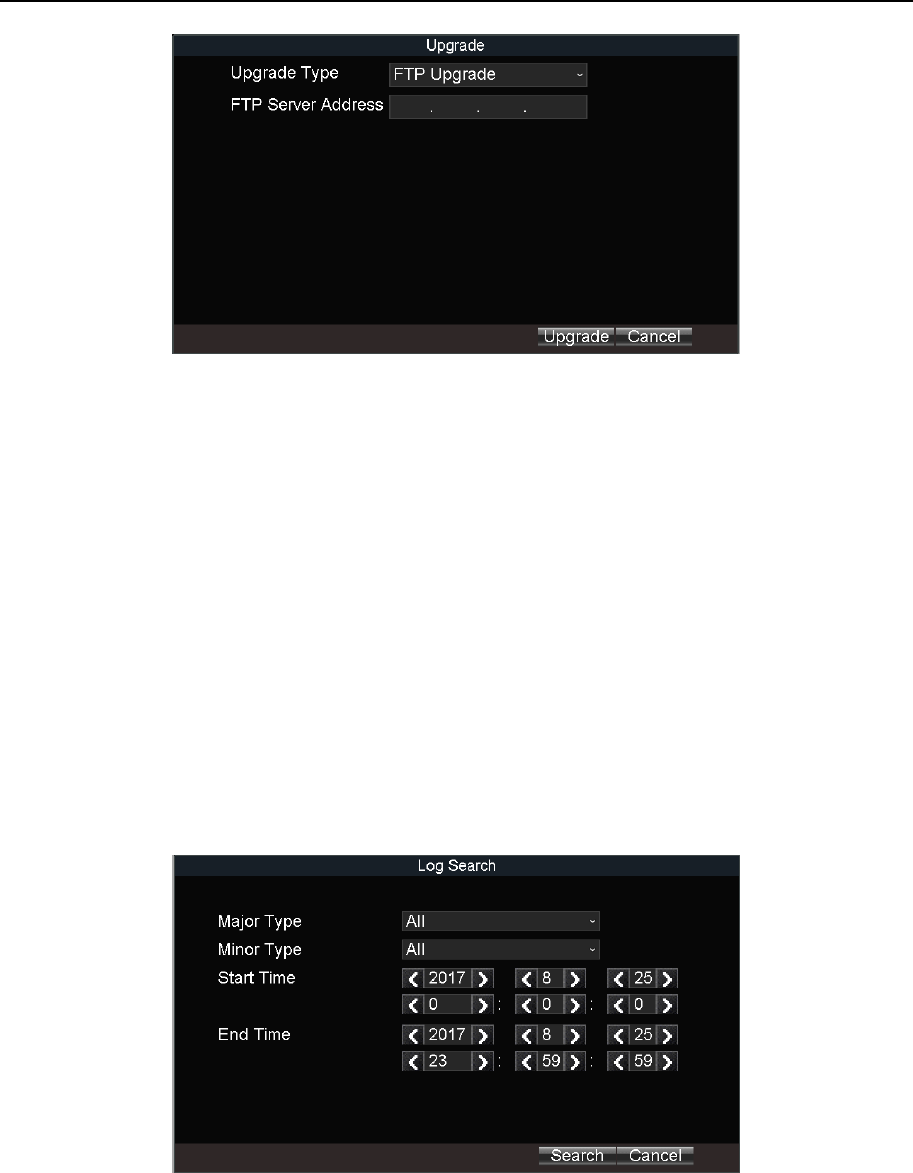
Mobile Network Video Recorder User Manual
74
Figure 15-4 Upgrade
Step 2 Select Upgrade Type as FTP Upgrade.
Step 3 Enter FTP Server Address.
Step 4 Click Upgrade to start upgrading and reboot the device to activate the new settings.
15.4 Log Operation
15.4.1 Search Log File
Purpose:
The operation, alarm, exception and information of the device can be stored in log files,
which can be viewed and exported at any time.
Step 1 Go to Menu > Maintenance > Log Search.
Figure 15-5 Log Search
Step 2 Select the Major Type and Minor Type of the logs.
Step 3 Specify the Start Time and End Time for the log search.
Step 4 Click Search. The matched logs will be displayed.
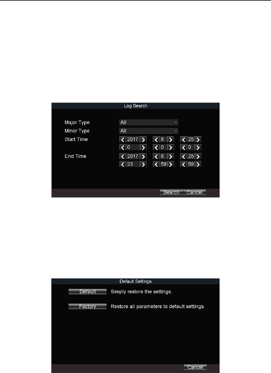
Mobile Network Video Recorder User Manual
75
15.4.2 Export Log File
Purpose:
The operation, alarm, exception and information of the device can be stored in log files,
which can be viewed and exported at any time.
Before you start:
Connect a backup device to the device.
Step 1 Go to Menu > Maintenance > Log Search.
Figure 15-6 Log Search
Step 2 Search log files. For detailed steps, refer to 15.4.1 Search Log File.
Step 3 Click Export.
15.5 Restore Default Settings
Step 1 Go to Menu > Maintenance > Default.
Figure 15-7 Restore Default Settings
Step 2 Select the restoring type from the following two options.
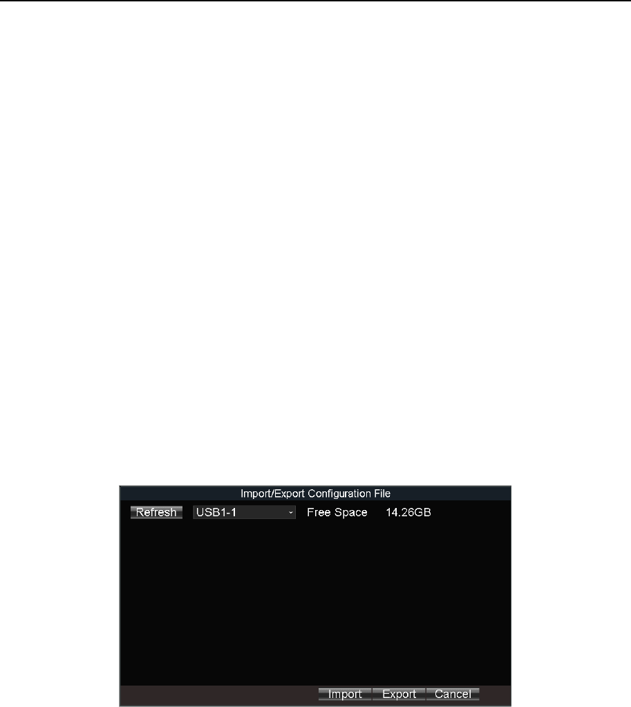
Mobile Network Video Recorder User Manual
76
Default: Restore all parameters, except the network (including IP address, subnet mask,
gateway, MTU, NIC working mode, default route, server port, etc.) and user account
parameters, to the factory default settings.
Factory: Restore all parameters to the factory default settings.
Step 3 Click OK.
Step 4 Click Yes in confirmation message box.
15.6 Import/Export Configuration File
15.6.1 Import Configuration File
Purpose:
The configuration files of one device can be imported to multiple device devices if they are to
be configured with the same parameters.
Before you start:
Connect a backup device that contains the configuration file to the device. The configuration
file should be stored on the root directory of the backup device.
Step 1 Go to Menu > Maintenance > Configuration.
Figure 15-8 Import/Export Configuration Files
Step 2 Click Import.
Step 3 Click Yes on confirmation message box.
15.6.2 Export Configuration File
Purpose:
The configuration files of the device can be exported to local device for backup.
Before you start:
Connect a USB storage device to the device.
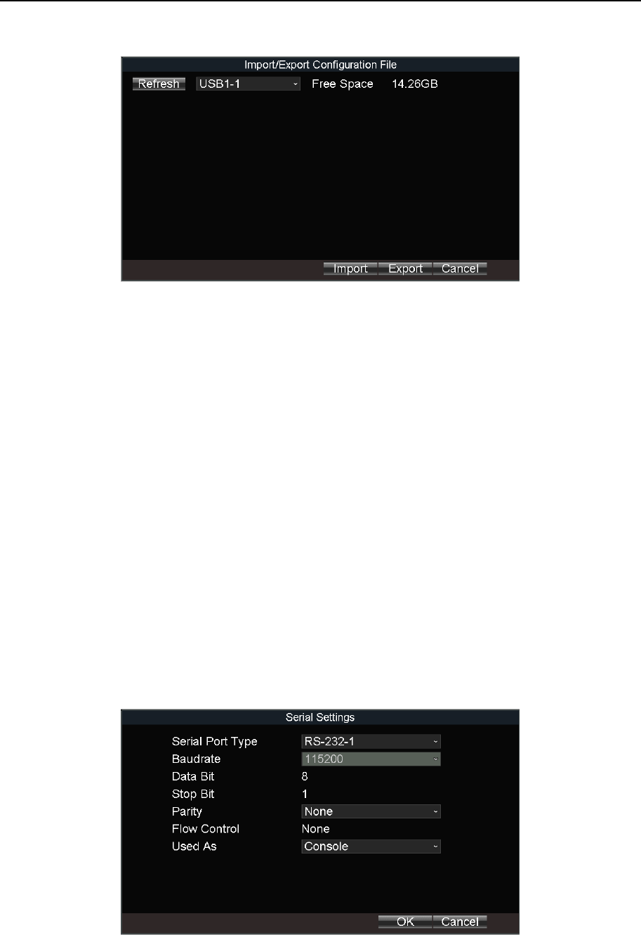
Mobile Network Video Recorder User Manual
77
Step 1 Go to Menu > Maintenance > Configuration.
Figure 15-9 Import/Export Configuration Files
Step 2 Click Export.
15.7 Serial Port Settings
Purpose:
Two types of serial ports are provided: RS-232 and RS-485.
The RS-232 port can be used in two ways:
Parameters Configuration: Connect a PC to the device through the PC serial port. Device
parameters can be configured by using software such as HyperTerminal. The serial port
parameters must be the same as of the device when connecting with the PC serial port.
Transparent Channel: Connect a serial device directly to the device. The serial device will
be controlled remotely by the PC through the network and the protocol of the serial
device. If alarm button is connected, select RS-232 usage as Transparent Channel.
The RS-485 port can be used for transparent channel only.
Step 1 Go to Menu > Basic Settings > Serial Port.
Figure 15-10 Serial Port Settings
Step 2 Edit parameters as required.

Mobile Network Video Recorder User Manual
78
Step 3 Click OK.
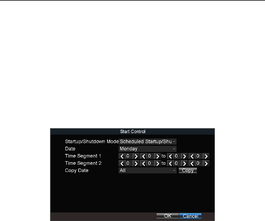
Mobile Network Video Recorder User Manual
79
Chapter 16 Shut Down Device
16.1 Enable Scheduled Startup/Shutdown
Purpose:
Set the scheduled startup/shutdown. The device will automatically start up/shut down
according the schedule.
Step 1 Go to Menu > Basic Settings > Start.
Step 2 Select Startup/Shutdown Mode as Scheduled Startup/Shutdown.
Figure 16-1 Scheduled Startup/Shutdown
Step 3 Select the Date to set the schedule.
Step 4 Specify the startup time segments. Two periods can be configured for each day. And
the time periods cannot be overlapped each other.
Step 5 Optionally, select Copy Date and click Copy to copy the settings to the selected day.
Step 6 Click OK.
16.2 Configure Delayed Shutdown
Purpose:
You can set the shutdown delay time (Vehicle Ignition Startup and Shutdown) for the device.
Step 1 Go to Menu > Basic Settings > Start.
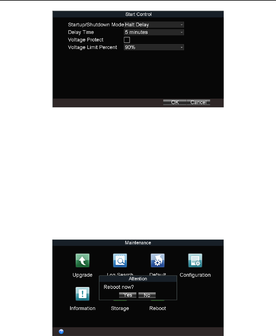
Mobile Network Video Recorder User Manual
80
Figure 16-2 Start Control
Step 2 Select Startup/Shutdown Mode as Halt Delay.
Step 3 Select Delay Time. The delay time ranges from 0 to 6 hours.
Step 4 Optionally, check Voltage Protect and select Voltage Limit Percent. If the voltage of
the device reaches the selected threshold, the device will shut down automatically.
Step 5 Click OK.
16.3 Reboot
Step 1 Go to Menu > Maintenance.
Step 2 Click Reboot and click Yes on confirmation message box to reboot the device.
Figure 16-3 Reboot
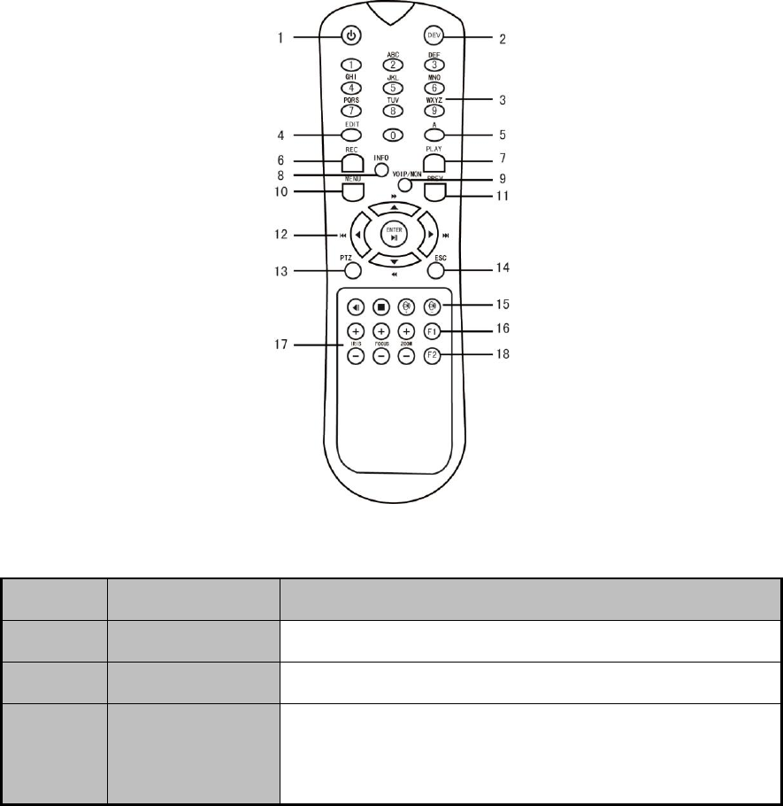
81
Chapter 17 Remote Control
Purpose:
The device can be controlled via IR remote control and mouse.
17.1 Buttons Description
Before you start:
Batteries (2×AAA) must be installed before operation.
Figure 17-1 Remote Control
Table 17-1 Description of the IR Remote Control Buttons
No.
Name
Description
1
Power
Reserved.
2
DEV
Input device number.
3
Digit buttons
Input the digit, symbol, and character.
Switch to the corresponding channel in Live View
mode.

Network Video Recorder Quick Start Guide
82
17.2 Operation Introduction
Purpose:
The chapter introduces basic device operation via remote control.
4
Edit
Enter the edit status, and then delete the character in
the front of the cursor.
Check a checkbox.
Clip videos In Playback mode.
5
A
Switch the input method when editing text field.
6
REC
Reserved.
7
PLAY
Enter video search interface.
8
INFO
Reserved.
9
VOIP/MON
Reserved.
10
MENU
Enter Main menu interface.
11
PREV
In live view, switch screen mode as single screen or
multi-screen.
12
Direction buttons
Navigate between fields and items in menus.
In playback interface, do fast forward, slow forward,
and reverse play operations.
In live view mode, switch among channels.
Enter
Check a checkbox.
In playback mode, play or pause the video.
In auto-switch mode, stop /start auto switch.
13
PTZ
Reserved.
14
ESC
Back to the previous menu.
15
Reserved
Reserved.
16
F1
In video search interface, select all videos.
17
PTZ control
buttons
Adjust the iris, focus, and zoom of a speed dome.
18
F2
Reserved.

Network Video Recorder Quick Start Guide
83
17.2.1 Build Connection with Device (Device No.: 255)
Purpose:
If the device number default one (255), press DEV to build connection between remote control and
device.
17.2.2 Build Connection with Device (Device No. is not 255)
Purpose:
Follow the steps to build connection between remote control and device when device number is
not 255.
Step 1 Go to Menu > Other Settings > Display.
Step 2 Click Set of Advanced Settings to view device number.
Step 3 Press DEV on the remote control.
Step 4 Enter the device number.
Step 5 Press ENTER on the remote control.
17.2.3 Enter Contents in Text Field
Step 1 Press Left/Right to position the cursor in the text field.
Step 2 Press Enter to edit.
Step 3 Press Edit to delete the previous content.
Step 4 Press A to switch input method.
Step 5 Press the numeric buttons to enter numbers, symbols, or characters.
Step 6 Press Enter to finish entering.
17.2.4 Click a Button
Step 1 Press Left/Right to position the cursor in the checkbox.
Step 2 Press Enter to click the button.
17.2.5 Check a Checkbox
Step 1 Press Left/Right to position the cursor in the checkbox.
Step 2 Press Enter/Edit to check the checkbox.
17.2.6 Select an Item from a Dropdown List
Step 1 Press Left/Right to position the cursor in the option.

Network Video Recorder Quick Start Guide
84
Step 2 Press Enter to pop up dropdown list.
Step 3 Press Up/Down to select an item.
Step 4 Press Enter to select it.
17.3 Troubleshooting
Purpose:
If there is no response after you press any button on the remote, follow the procedure below to
troubleshoot.
Step 1 Go to Menu > Other Settings > Display
Step 2 Click Set of Advanced Settings.
Step 3 Edit device number. The default number is 255.
Step 4 Press DEV on the remote control.
Step 5 Enter the device number.
Step 6 Press ENTER on the remote control.
17.4 Set Areas with Remote Control
Step 1 Click the Area Settings button.
Step 2 Press the Edit key on the remote control and a red block appears on the screen.
Step 3 Press the Direction keys on the remote control to adjust the position of the red block.
Step 4 Press the Enter key on the remote control to save the position of the red block.
Step 5 Press the Direction keys on the remote control to adjust the size of the block.
Step 6 Press the Enter key on the remote control to save the size of the block.
Step 7 Press the Menu key on the remote control to set the detection sensitivity. You can set the
level as 1~6 or off. Click OK to save the settings.
Step 8 You can press the A key on the remote control to clear all the mask areas.
Press the Enter key on the remote control to save the settings and then press Esc key to exit.

Network Video Recorder Quick Start Guide
85
Chapter 18 Appendix
18.1 Glossary
3G/4G: 3G/4G refers to the 3rd/4th-generation telecommunication technology which is the
high speed transmission of the cell data. The 3G/4G service can transmit sound and other data
simultaneously and the bitrate is up to hundreds kbps.
DHCP: DHCP is the acronym of Dynamic Host Configuration Protocol, and it is one of the
TCP/IP protocol stacks, it is used to assign the dynamic IP address to the host on the network.
Dual Stream: Dual stream is a technology used to record high resolution video locally while
transmitting a lower resolution stream over the network.
GNSS: A satellite navigation system is a system of satellites that provide autonomous
geo-spatial positioning with global coverage. It allows small electronic receivers to determine
their location (longitude, latitude, and altitude) to high precision (within a few meters) using
time signals transmitted along a line of sight by radio from satellites. The signals also allow the
electronic receivers to calculate the current local time to high precision, which allows time
synchronization. A satellite navigation system with global coverage may be termed GNSS
(Global Navigation Satellite System).
GPS: GPS (Global Positioning System) is a space-based global navigation satellite system that
provides location and time information in all weather and anywhere on or near the earth,
where there is an unobstructed line of sight to 4 or more GPS satellite.
G-Sensor: G-sensor (Gravity-sensor) can sense the change of the accelerated force, such as the
shaking, free falling and lifting. And those changes of the accelerated force can be sensed by
the G-sensor in a means of electrical signals, and then link certain action according to the
changes of the electrical signals. When applied in the hard disk protection, G-Sensor can check
the current status of the hard disk in case of the affection of the R/W function by the sudden
change of the accelerated force.
NTP: NTP is Network Time Protocol, and it is a protocol used to synchronize the computer
time.
Sensor-In: Sensor-In is a built-in module on the device used to record the movement
information of the vehicle, such as the braking, left-turning and right-turning and so on. The
information can be used for analysis of an accident.
Transparent Channel: Transparent channel is a mechanism which analyzes the IP datagram
and sends it by the serial interface. It extends the control distance of the serial devices and for
the user, only the point to point transmission is seen and the actual transmission is ignored.
VPDN: Virtual Private Dial-up Network is a network that uses primarily public
telecommunication infrastructure, such as the internet, to provide remote office or travelling
users’ access to a central organization network, such as the ISP private network, financial
network and so on.

Network Video Recorder Quick Start Guide
86
Wi-Fi: Wi-Fi is a mechanism of the wireless connecting electronic devices. A device enabled
with Wi-Fi such as PC, video game console, can connect to the internet via a wireless network
access point.
18.2 FAQ
• Why does my device make a beeping sound after booting?
The possible reasons for the warning beep on the device are as follows:
a) There is no HDD installed in the device.
b) The HDD is not initialized.
c) HDD error
To cancel the beeping sound and use the device without HDD, enter the Exception Settings
interface.
• Device fails to start up after connecting the power.
Possible reasons:
a) Incorrect voltage input (6 ~ 36 VDC) and power consumption (≥ 50W).
b) The HDD lock is not closed.
c) The power connections are incorrect.
d) The motherboard or power functions abnormally. In case of hardware failure, please
contact the supplier of the product.
• Fail to connect 3G/4G.
Possible reasons for 3G/4G connection failure are as follows:
a) Dialing is not enabled.
b) APN, dial number, user name and password should be set for 3G/4G VPDN private
network.
c) No 3G/4G antenna connected. When both the master/slave antennas are connected,
locate them vertically with above 20cm distance from each other.
d) SIM card is out of service or 3G/4G service is not opened.
• Fail to connect to Wi-Fi.
Please check the following settings:
a) The SSID, encryption type or password are entered incorrectly.
b) AP (access point) or router works abnormally.
c) No Wi-Fi antenna connected or the antenna is not vertically located.

Network Video Recorder Quick Start Guide
87
• The device cannot be accessed via platform (iVMS) after successful connection to 3G/4G or
Wi-Fi.
Possible reasons:
a) The parameters (e.g., server IP, device registered ID, etc.) of the platform are configured
incorrectly.
b) The platform works abnormally.
• Fail to obtain satellite positioning information.
Possible reasons:
a) The satellite positioning antenna is not placed outdoor.
b) There is no satellite positioning module (built-in or external) available for the device.
c) The Position Module are configured incorrectly.
• Why does the device seem unresponsive when operating with the IR remote control?
a) The batteries are installed correctly, making sure that the polarities of the batteries are not
reversed.
b) The batteries are fresh and are not out of power.
c) The remote sensor is not covered or blocked by other object.
d) There are no fluorescent lamps in use nearby.
• No backup device is detected when exporting recorded files?
Possible reasons:
a) There is no backup device connected with the device.
b) The device and your backup device are not compatible.
c) Initialize the backup device before using.
d) The backup device is damaged.
040300171121