Hangzhou Hikvision Digital Technology T03C0D00 Wireless Transmitter & Receiver User Manualx
Hangzhou Hikvision Digital Technology Co., Ltd. Wireless Transmitter & Receiver User Manualx
UserManual.wiki
>
Hangzhou Hikvision Digital Technology
>
T03C0D00 User Manual
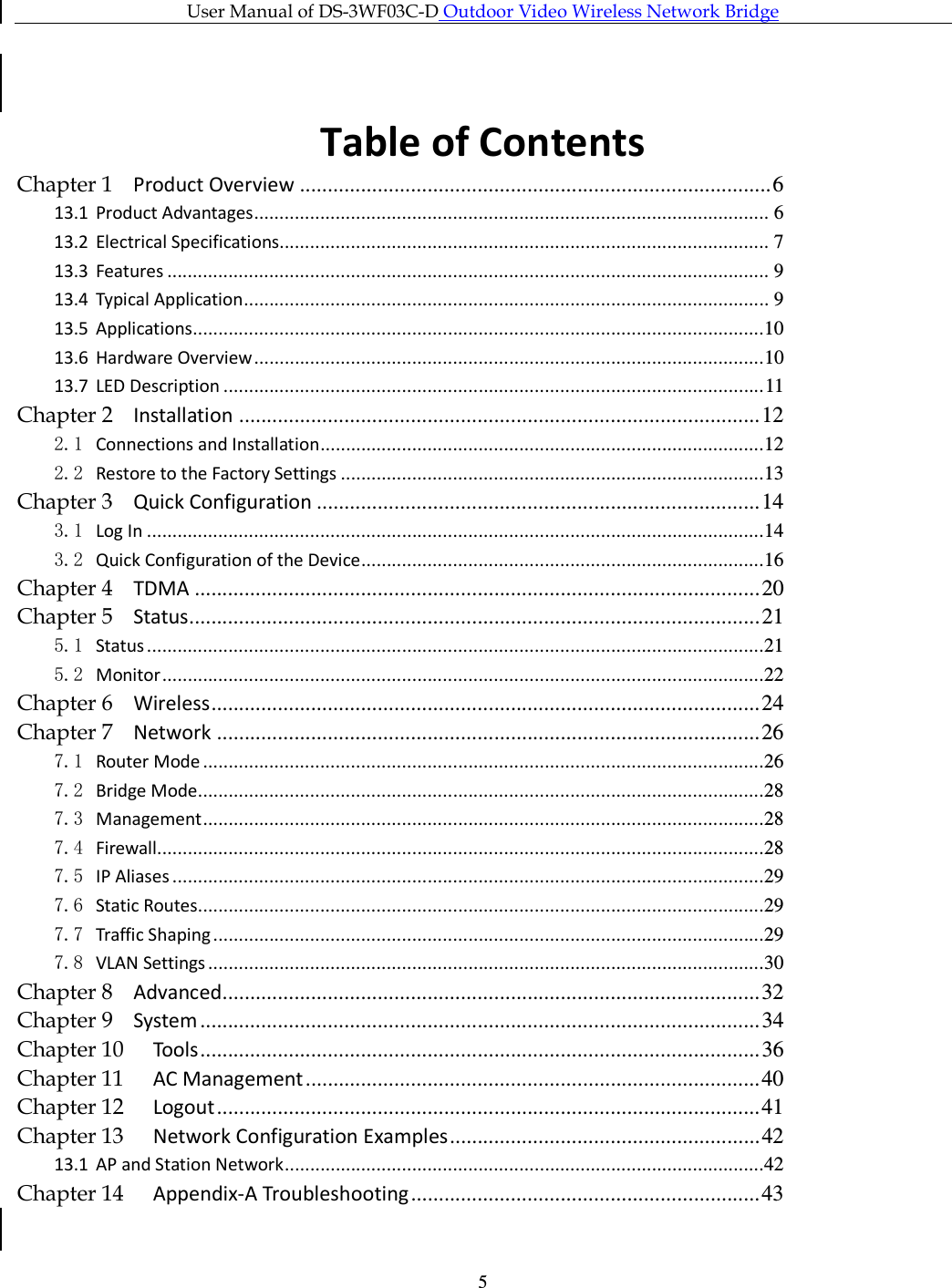
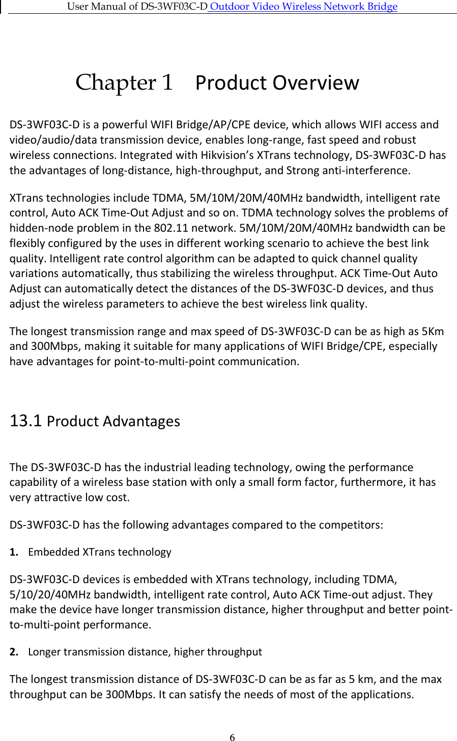
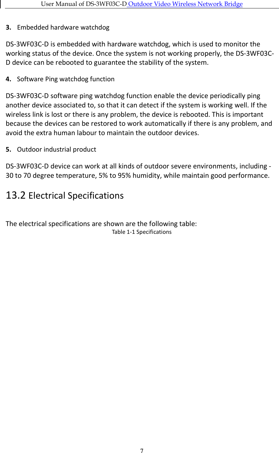
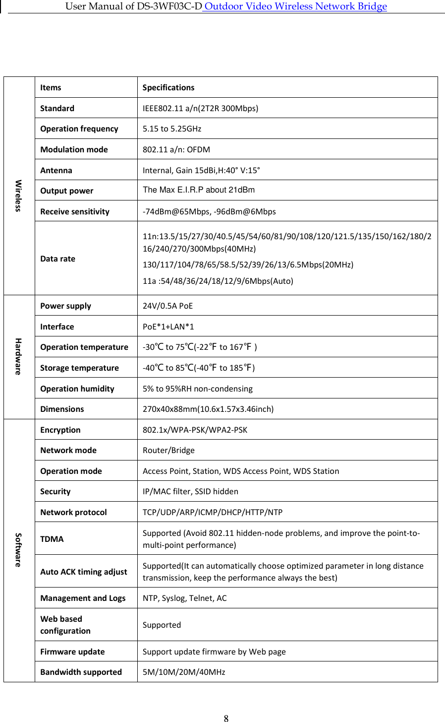
User Manual
Navigation menu
Upload a User Manual
Namespaces
Wiki Guide
HTML
PDF
Info
Views
User Manual
Discussion / Help
Navigation