Hangzhou Hikvision Digital Technology T03C0D00 Wireless Transmitter & Receiver User Manualx
Hangzhou Hikvision Digital Technology Co., Ltd. Wireless Transmitter & Receiver User Manualx
User Manual

DS-3WF03C-D Outdoor Video Wireless Network
Bridge
User Manual

User Manual of DS-3WF03C-D Outdoor Video Wireless Network Bridge
2
User Manual
COPYRIGHT ©2016 Hangzhou Hikvision Digital Technology Co., Ltd.
ALL RIGHTS RESERVED.
Any and all information, including, among others, wordings, pictures, graphs are the properties of
Hangzhou Hikvision Digital Technology Co., Ltd. or its subsidiaries (hereinafter referred to be
“Hikvision”). This user manual (hereinafter referred to be “the Manual”) cannot be reproduced,
changed, translated, or distributed, partially or wholly, by any means, without the prior written
permission of Hikvision. Unless otherwise stipulated, Hikvision does not make any warranties,
guarantees or representations, express or implied, regarding to the Manual.
About this Manual
This Manual is applicable to DS-3WF03C-D outdoor video wireless network bridge, the Manual includes
instructions for using and managing the product. Pictures, charts, images and all other information
hereinafter are for description and explanation only. The information contained in the Manual is
subject to change, without notice, due to firmware updates or other reasons. Please find the latest
version in the company website (http://overseas.hikvision.com/en/).
Please use this user manual under the guidance of professionals.
Trademarks Acknowledgement
and other Hikvision’s trademarks and logos are the properties of Hikvision in various
jurisdictions. Other trademarks and logos mentioned below are the properties of their respective
owners.
Legal Disclaimer
TO THE MAXIMUM EXTENT PERMITTED BY APPLICABLE LAW, THE PRODUCT DESCRIBED, WITH ITS
HARDWARE, SOFTWARE AND FIRMWARE, IS PROVIDED “AS IS”, WITH ALL FAULTS AND ERRORS, AND
HIKVISION MAKES NO WARRANTIES, EXPRESS OR IMPLIED, INCLUDING WITHOUT LIMITATION,
MERCHANTABILITY, SATISFACTORY QUALITY, FITNESS FOR A PARTICULAR PURPOSE, AND NON-
INFRINGEMENT OF THIRD PARTY. IN NO EVENT WILL HIKVISION, ITS DIRECTORS, OFFICERS, EMPLOYEES,
OR AGENTS BE LIABLE TO YOU FOR ANY SPECIAL, CONSEQUENTIAL, INCIDENTAL, OR INDIRECT
DAMAGES, INCLUDING, AMONG OTHERS, DAMAGES FOR LOSS OF BUSINESS PROFITS, BUSINESS
INTERRUPTION, OR LOSS OF DATA OR DOCUMENTATION, IN CONNECTION WITH THE USE OF THIS
PRODUCT, EVEN IF HIKVISION HAS BEEN ADVISED OF THE POSSIBILITY OF SUCH DAMAGES.
REGARDING TO THE PRODUCT WITH INTERNET ACCESS, THE USE OF PRODUCT SHALL BE WHOLLY AT
YOUR OWN RISKS. HIKVISION SHALL NOT TAKE ANY RESPONSIBILITES FOR ABNORMAL OPERATION,
PRIVACY LEAKAGE OR OTHER DAMAGES RESULTING FROM CYBER ATTACK, HACKER ATTACK, VIRUS
INSPECTION, OR OTHER INTERNET SECURITY RISKS; HOWEVER, HIKVISION WILL PROVIDE TIMELY
TECHNICAL SUPPORT IF REQUIRED.
SURVEILLANCE LAWS VARY BY JURISDICTION. PLEASE CHECK ALL RELEVANT LAWS IN YOUR
JURISDICTION BEFORE USING THIS PRODUCT IN ORDER TO ENSURE THAT YOUR USE CONFORMS THE
APPLICABLE LAW. HIKVISION SHALL NOT BE LIABLE IN THE EVENT THAT THIS PRODUCT IS USED WITH
ILLEGITIMATE PURPOSES.

User Manual of DS-3WF03C-D Outdoor Video Wireless Network Bridge
3
IN THE EVENT OF ANY CONFLICTS BETWEEN THIS MANUAL AND THE APPLICABLE LAW, THE LATER
PREVAILS.
Regulatory Information
FCC Information
Please take attention that changes or modification not expressly approved by the party responsible for
compliance could void the user’s authority to operate the equipment.
FCC compliance: This equipment has been tested and found to comply with the limits for a Class A
digital device, pursuant to part 15 of the FCC Rules. These limits are designed to provide reasonable
protection against harmful interference when the equipment is operated in a commercial environment.
This equipment generates, uses, and can radiate radio frequency energy and, if not installed and used
in accordance with the instruction manual, may cause harmful interference to radio communications.
Operation of this equipment in a residential area is likely to cause harmful interference in which case
the user will be required to correct the interference at his own expense.
FCC Conditions
This device complies with part 15 of the FCC Rules. Operation is subject to the following two conditions:
1. This device may not cause harmful interference.
2. This device must accept any interference received, including interference that may cause undesired
operation.
Attention that changes or modification not expressly approved by the party responsible for compliance
could void the user’s authority to operate the equipment.
Note: This product has been tested and found to comply with the limits for a Class B digital device,
pursuant to Part 15 of the FCC Rules. These limits are designed to provide reasonable protection
against harmful interference in a residential installation. This product generates, uses, and can radiate
radio frequency energy and, if not installed and used in accordance with the instructions, may cause
harmful interference to radio communications. However, there is no guarantee that interference will
not occur in a particular installation. If this product does cause harmful interference to radio or
television reception, which can be determined by turning the equipment off and on, the user is
encouraged to try to correct the interference by one or more of the following measures:
—Reorient or relocate the receiving antenna.
—Increase the separation between the equipment and receiver.
—Connect the equipment into an outlet on a circuit different from that to which the receiver is
connected.
—Consult the dealer or an experienced radio/TV technician for help.
This equipment should be installed and operated with a minimum distance 20cm between the radiator
and your body
EU Conformity Statement
This product and - if applicable - the supplied accessories too are marked with "CE" and
comply therefore with the applicable harmonized European standards listed under the EMC
Directive 2014/30/EU, the LVD Directive 2014/35/EU, the RoHS Directive 2011/65/EU.

User Manual of DS-3WF03C-D Outdoor Video Wireless Network Bridge
4
2012/19/EU (WEEE directive): Products marked with this symbol cannot be disposed of as
unsorted municipal waste in the European Union. For proper recycling, return this product to
your local supplier upon the purchase of equivalent new equipment, or dispose of it at
designated collection points. For more information see: www.recyclethis.info
2006/66/EC (battery directive): This product contains a battery that cannot be disposed of as
unsorted municipal waste in the European Union. See the product documentation for
specific battery information. The battery is marked with this symbol, which may include
lettering to indicate cadmium (Cd), lead (Pb), or mercury (Hg). For proper recycling, return
the battery to your supplier or to a designated collection point. For more information see:
www.recyclethis.info
Industry Canada ICES-003 Compliance
This device meets the CAN ICES-3 (A)/NMB-3(A) standards requirements.

User Manual of DS-3WF03C-D Outdoor Video Wireless Network Bridge
5
Table of Contents
Chapter 1 Product Overview ..................................................................................... 6
13.1 Product Advantages ..................................................................................................... 6
13.2 Electrical Specifications................................................................................................ 7
13.3 Features ...................................................................................................................... 9
13.4 Typical Application ....................................................................................................... 9
13.5 Applications ................................................................................................................ 10
13.6 Hardware Overview .................................................................................................... 10
13.7 LED Description .......................................................................................................... 11
Chapter 2 Installation .............................................................................................. 12
2.1 Connections and Installation ....................................................................................... 12
2.2 Restore to the Factory Settings ................................................................................... 13
Chapter 3 Quick Configuration ................................................................................ 14
3.1 Log In ......................................................................................................................... 14
3.2 Quick Configuration of the Device ............................................................................... 16
Chapter 4 TDMA ...................................................................................................... 20
Chapter 5 Status....................................................................................................... 21
5.1 Status ......................................................................................................................... 21
5.2 Monitor ...................................................................................................................... 22
Chapter 6 Wireless ................................................................................................... 24
Chapter 7 Network .................................................................................................. 26
7.1 Router Mode .............................................................................................................. 26
7.2 Bridge Mode ............................................................................................................... 28
7.3 Management .............................................................................................................. 28
7.4 Firewall....................................................................................................................... 28
7.5 IP Aliases .................................................................................................................... 29
7.6 Static Routes............................................................................................................... 29
7.7 Traffic Shaping ............................................................................................................ 29
7.8 VLAN Settings ............................................................................................................. 30
Chapter 8 Advanced ................................................................................................. 32
Chapter 9 System ..................................................................................................... 34
Chapter 10 Tools ..................................................................................................... 36
Chapter 11 AC Management .................................................................................. 40
Chapter 12 Logout .................................................................................................. 41
Chapter 13 Network Configuration Examples ........................................................ 42
13.1 AP and Station Network .............................................................................................. 42
Chapter 14 Appendix-A Troubleshooting ............................................................... 43

User Manual of DS-3WF03C-D Outdoor Video Wireless Network Bridge
6
Chapter 1 Product Overview
DS-3WF03C-D is a powerful WIFI Bridge/AP/CPE device, which allows WIFI access and
video/audio/data transmission device, enables long-range, fast speed and robust
wireless connections. Integrated with Hikvision’s XTrans technology, DS-3WF03C-D has
the advantages of long-distance, high-throughput, and Strong anti-interference.
XTrans technologies include TDMA, 5M/10M/20M/40MHz bandwidth, intelligent rate
control, Auto ACK Time-Out Adjust and so on. TDMA technology solves the problems of
hidden-node problem in the 802.11 network. 5M/10M/20M/40MHz bandwidth can be
flexibly configured by the uses in different working scenario to achieve the best link
quality. Intelligent rate control algorithm can be adapted to quick channel quality
variations automatically, thus stabilizing the wireless throughput. ACK Time-Out Auto
Adjust can automatically detect the distances of the DS-3WF03C-D devices, and thus
adjust the wireless parameters to achieve the best wireless link quality.
The longest transmission range and max speed of DS-3WF03C-D can be as high as 5Km
and 300Mbps, making it suitable for many applications of WIFI Bridge/CPE, especially
have advantages for point-to-multi-point communication.
13.1 Product Advantages
The DS-3WF03C-D has the industrial leading technology, owing the performance
capability of a wireless base station with only a small form factor, furthermore, it has
very attractive low cost.
DS-3WF03C-D has the following advantages compared to the competitors:
1. Embedded XTrans technology
DS-3WF03C-D devices is embedded with XTrans technology, including TDMA,
5/10/20/40MHz bandwidth, intelligent rate control, Auto ACK Time-out adjust. They
make the device have longer transmission distance, higher throughput and better point-
to-multi-point performance.
2. Longer transmission distance, higher throughput
The longest transmission distance of DS-3WF03C-D can be as far as 5 km, and the max
throughput can be 300Mbps. It can satisfy the needs of most of the applications.

User Manual of DS-3WF03C-D Outdoor Video Wireless Network Bridge
7
3. Embedded hardware watchdog
DS-3WF03C-D is embedded with hardware watchdog, which is used to monitor the
working status of the device. Once the system is not working properly, the DS-3WF03C-
D device can be rebooted to guarantee the stability of the system.
4. Software Ping watchdog function
DS-3WF03C-D software ping watchdog function enable the device periodically ping
another device associated to, so that it can detect if the system is working well. If the
wireless link is lost or there is any problem, the device is rebooted. This is important
because the devices can be restored to work automatically if there is any problem, and
avoid the extra human labour to maintain the outdoor devices.
5. Outdoor industrial product
DS-3WF03C-D device can work at all kinds of outdoor severe environments, including -
30 to 70 degree temperature, 5% to 95% humidity, while maintain good performance.
13.2 Electrical Specifications
The electrical specifications are shown are the following table:
Table 1-1 Specifications

User Manual of DS-3WF03C-D Outdoor Video Wireless Network Bridge
8
Items Specifications
Wireless
Standard IEEE802.11 a/n(2T2R 300Mbps)
Operation frequency 5.15 to 5.25GHz
Modulation mode 802.11 a/n: OFDM
Antenna Internal, Gain 15dBi,H:40° V:15°
Output power
Receive sensitivity -74dBm@65Mbps, -96dBm@6Mbps
Data rate
11n:13.5/15/27/30/40.5/45/54/60/81/90/108/120/121.5/135/150/162/180/2
16/240/270/300Mbps(40MHz)
130/117/104/78/65/58.5/52/39/26/13/6.5Mbps(20MHz)
11a :54/48/36/24/18/12/9/6Mbps(Auto)
Hardware
Power supply 24V/0.5A PoE
Interface PoE*1+LAN*1
Operation temperature -30℃ to 75℃(-22℉ to 167℉ )
Storage temperature -40℃ to 85℃(-40℉ to 185℉)
Operation humidity 5% to 95%RH non-condensing
Dimensions 270x40x88mm(10.6x1.57x3.46inch)
Software
Encryption 802.1x/WPA-PSK/WPA2-PSK
Network mode Router/Bridge
Operation mode Access Point, Station, WDS Access Point, WDS Station
Security IP/MAC filter, SSID hidden
Network protocol TCP/UDP/ARP/ICMP/DHCP/HTTP/NTP
TDMA Supported (Avoid 802.11 hidden-node problems, and improve the point-to-
multi-point performance)
Auto ACK timing adjust Supported(It can automatically choose optimized parameter in long distance
transmission, keep the performance always the best)
Management and Logs NTP, Syslog, Telnet, AC
Web based
configuration Supported
Firmware update Support update firmware by Web page
Bandwidth supported 5M/10M/20M/40MHz
The Max E.I.R.P about 21dBm

User Manual of DS-3WF03C-D Outdoor Video Wireless Network Bridge
9
13.3 Features
High performance 802.11n 2×2 MIMO chip
Longest transmission range: 5Km, and max transmission throughput: 300Mbps
Integrated XTrans technology, including TDMA, intelligent rate control, Auto ACK
Time-out adjust
TDMA solves the problems of hidden-node problem in the 802.11 network, thus
having better long-distance and PTMP performance
5 operation mode: Access Point, Station, WDS Access Point, WDS Station, WDS
Repeater
Point-to-point, point-to-multipoint connection
Unique RF and antenna design enables long-range transmission
Wireless multimedia optimization technology guarantees video/audio transmission
QoS
Web based working scenario selection makes the installation and setting much
easier
Reliable PoE power supply
Web-based configuration, easy to use
Waterproof housing and accessory kit protects
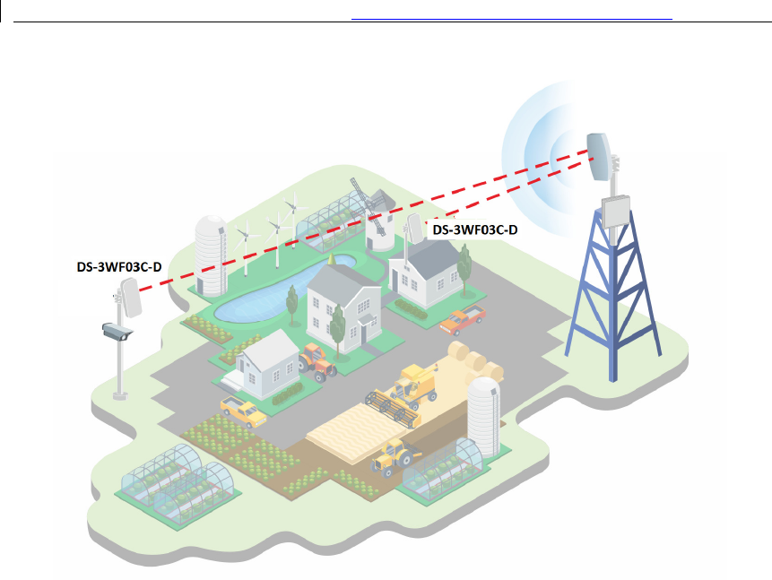
13.4 Typical Application
The DS-3WF03C-D usage examples are shown in figure; it can be used as WIFI AP, CPE,
or outdoor PTP, PTMP topology. Therefore, DS-3WF03C-D is suitable for various
applications like wireless video transmission, and wireless signal coverage.
User Manual of
13.5
Applications
DS-3WF03C-D
can be used widely in the following applications:
•
Wireless video surveillance (free
•
Carrier wireless backhaul and rural area internet last
•
Enterprise local area network inter
•
WIFI signal coverage and rural wireless coverage
13.6
Hardware Overview
DS-3WF03C-D
’s hardware information is described in the following
User Manual of
DS-3WF03C-D
Outdoor Video Wireless Network
10
Figure 1-1 Typical Application
can be used widely in the following applications:
Wireless video surveillance (free
-
way, city, police, oil pipeline, forest and etc.)
Carrier wireless backhaul and rural area internet l
ast-
mile wireless solution
Enterprise local area network inter
-connection
WIFI signal coverage and rural wireless coverage
Hardware Overview
’s hardware information is described in the followi
ng t
able:
Outdoor Video Wireless Network
Bridge
way, city, police, oil pipeline, forest and etc.)
mile wireless solution
able:

User Manual of DS-3WF03C-D Outdoor Video Wireless Network Bridge
11
Table 1-2 Hardware information
Hardware Specifications
CPU/Baseband
Radio
Atheros AR
9344
Memory
64
MB DRAM, 8MB Flash
Physical Interface
2×10/100M Base
-
TX (Cat. 5/5E, RJ
-
45) Ports
LED Status
Power, LAN, WLAN, 3×Link Quality
Power supply
POE, Power Adapter 24V/0.5A
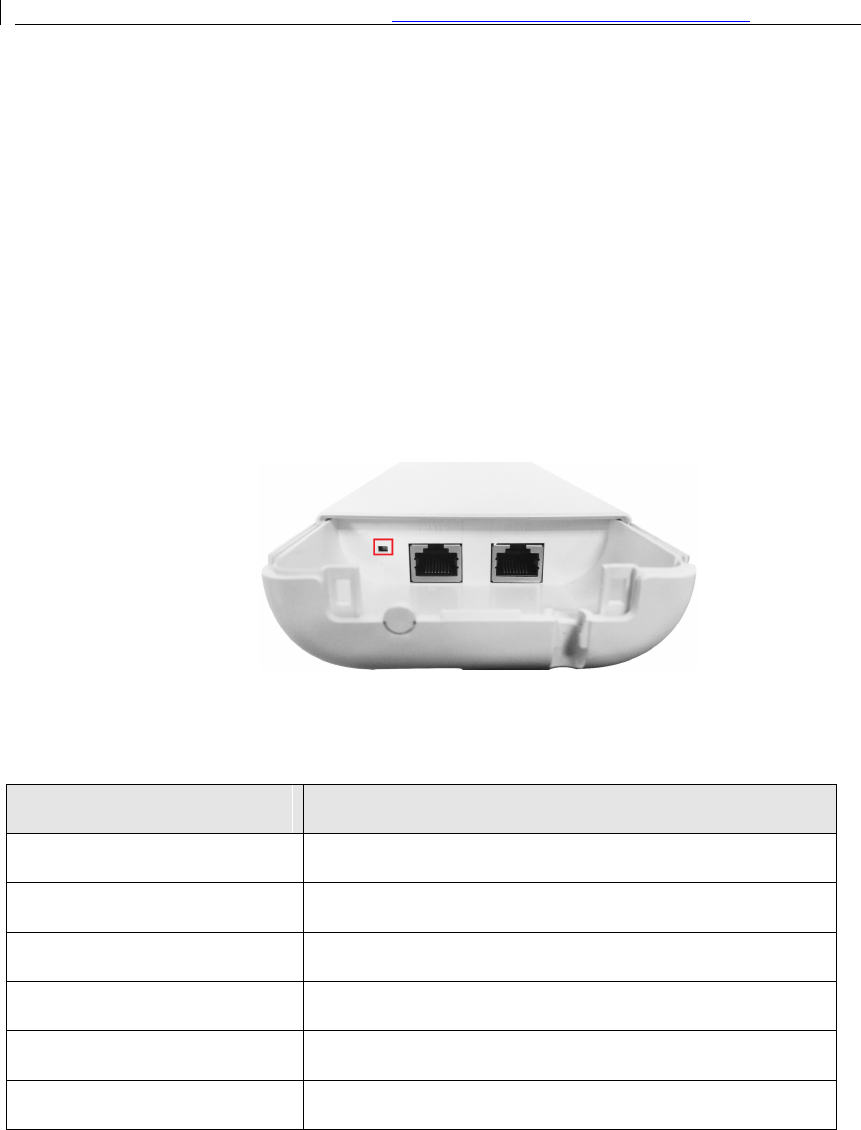
13.7 LED Description
The LEDs of DS-3WF03C-D can be divided to 2 groups. One group of LEDs are Indicators,
including the left 3 LEDs of figure, and they are Power, LAN and WAN indicators. The
other group of LEDs are Link Quality, including the right 3 LEDs of figure, shown the
signal strength.
Table 1-3 LED Information
LED
Color
Status
POWER
Green
ON = Device Power on
LAN
Green
ON = Device connected to the network
WLAN Green
OFF = Device radio is OFF
ON = Device radio is ON, but not sending or
receiving date through the wireless LAN.
BLINK= Device radio is ON, and sending or receiving
date through the wireless LAN.
Link Quality
Red
Showing the signal strength between the device
and the network.
Green is ON = good quality
Yellow is ON = medium quality
Red = poor quality or no link
Yellow
Green
User Manual of DS-3WF03C-D Outdoor Video Wireless Network Bridge
12
Chapter 2 Installation
This chapter describes how to install DS-3WF03C-D device in the bridge mode, and the
installation method of router mode can be seen in Chapter 7.
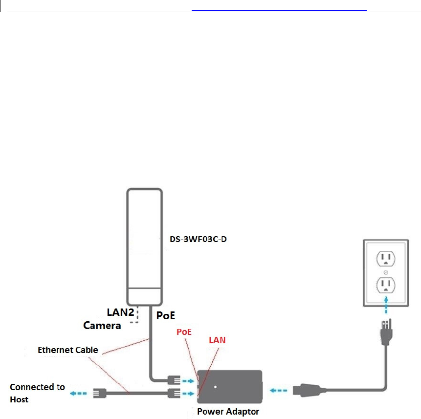
2.1
Connections and Installation
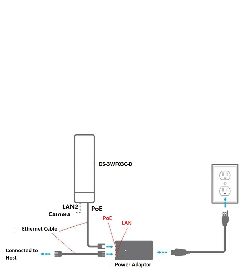
The connection of DS-3WF03C-D device to POE and power supply is shown in figure.
Figure 2-1 Connections at Bridge mode
DS-3WF03C-D has 2 RJ45 ports, and they are marked with “POE” and “LAN2” separately.
In the bridge mode, please connect the device with the POE power adaptor in the
following way:
1.
Remove the bottom cover from the DS-3WF03C-D device, and you will see there are
2 RJ45 ports marked with “POE” and “LAN2”.
2.
Using an Ethernet cable to connect the POE power adaptor and the “POE” port of
the DS-3WF03C-D device.
3.
Connect the POE adaptor to the normal power supply board.
4.
Normally, “LAN2” port of the DS-3WF03C-D can be connected to IP Camera and
User Manual of
other devices, or leave it unconnected
5.
Mount the DS-
3WF03C
2.2
Restore to the Factory
In some cases, uses can restore the device to the factory settings by the following way in
the figure
. Push the reset button for 5~10 seconds until all LED
will restore to the factory setting. During this process, the
will be connected and disconnected twice.
For default, all the factory settings are shown in the following
Table
Items
IP address
User name
Password
Output power
Encryption
Network mode
User Manual of
DS-3WF03C-D
Outdoor Video Wireless Network
13
other devices, or leave it unconnected
3WF03C
-D
securely to the pole by locking the strap tightly.
Restore to the Factory
Settings
In some cases, uses can restore the device to the factory settings by the following way in
. Push the reset button for 5~10 seconds until all LED
s are
on. Th
will restore to the factory setting. During this process, the
DS-3
WF03C
will be connected and disconnected twice.
Figure 2-2 Restore to the factory settings
For default, all the factory settings are shown in the following
table.
Table
2-1 Main parameters at the factory settings
Default Settings
192.168.1.35/192.168.1.36
admin
admin
High
WPA->WPA2->CCMP-
>Password:1234567890abc
Bridge
Outdoor Video Wireless Network
Bridge
securely to the pole by locking the strap tightly.
In some cases, uses can restore the device to the factory settings by the following way in
on. Th
en the device
WF03C
-D’s RJ45 ports
>Password:1234567890abc
User Manual of DS-3WF03C-D Outdoor Video Wireless Network Bridge
14
Chapter 3 Quick Configuration
This chapter describe how to configure the device quickly.
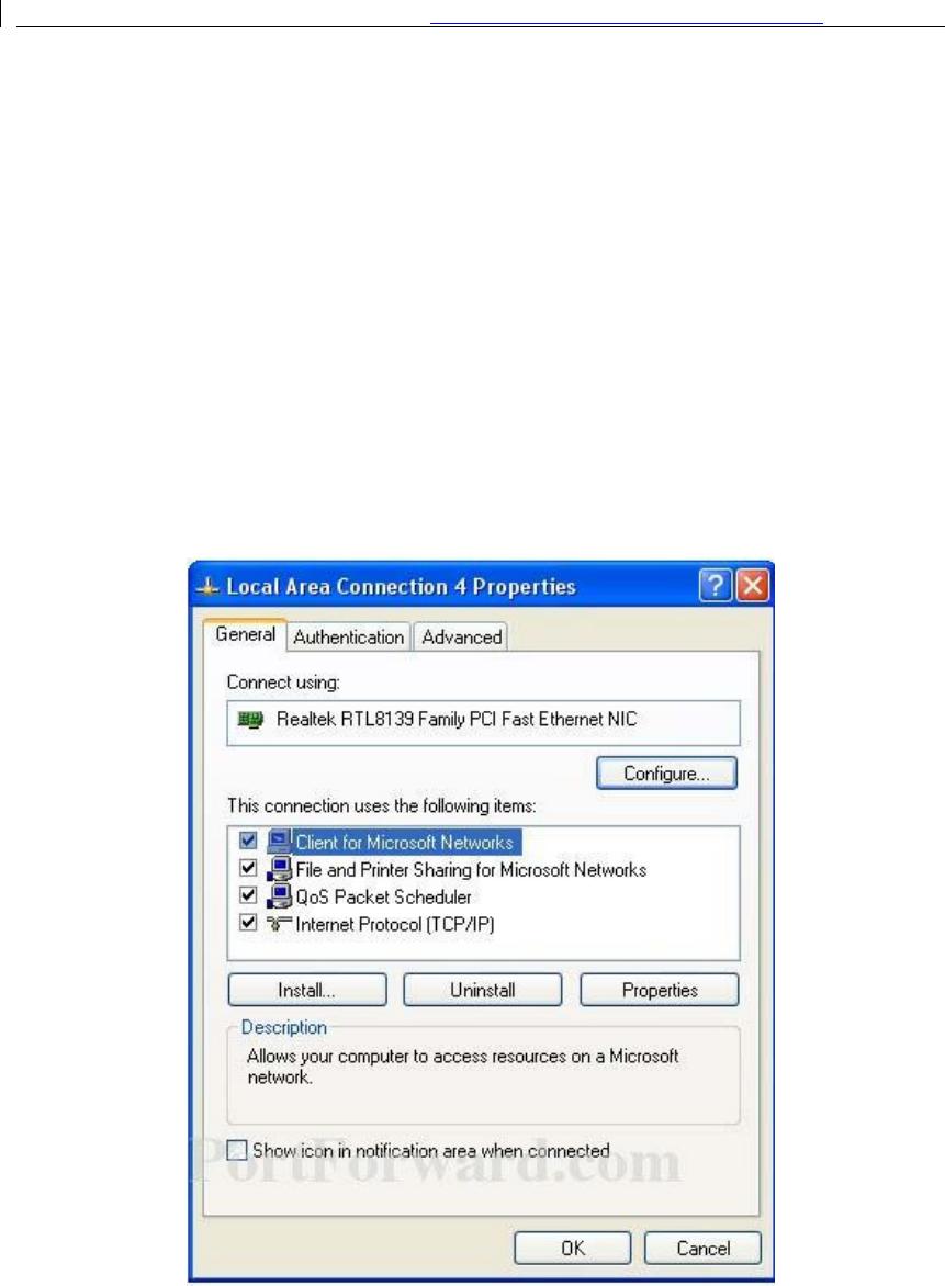
3.1
Log In
To log in the DS-3WF03C-D device, user needs to configure the TCP/IP of your computer
first as the following steps:
1.
Right click Local Area Connection icon of your computer and click properties, then
click Continue, the Local Area Connection Properties dialog box appears as figure.
Figure 3-1 Local Area Connection Properties
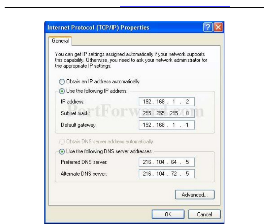
2.
Select Internet Protocol (TCP/IP) and click Properties button, and the following
dialog box appear:
User Manual of DS-3WF03C-D Outdoor Video Wireless Network Bridge
15
Figure 3-2 IP settings
3.
In the above figure, IP address should be set to 192.168.1.*, here * can be a number
between 1-255 (but not 36) since the DS-3WF03C-D
(
T/R
)
default IP address is
192.168.1.35/36.
4.
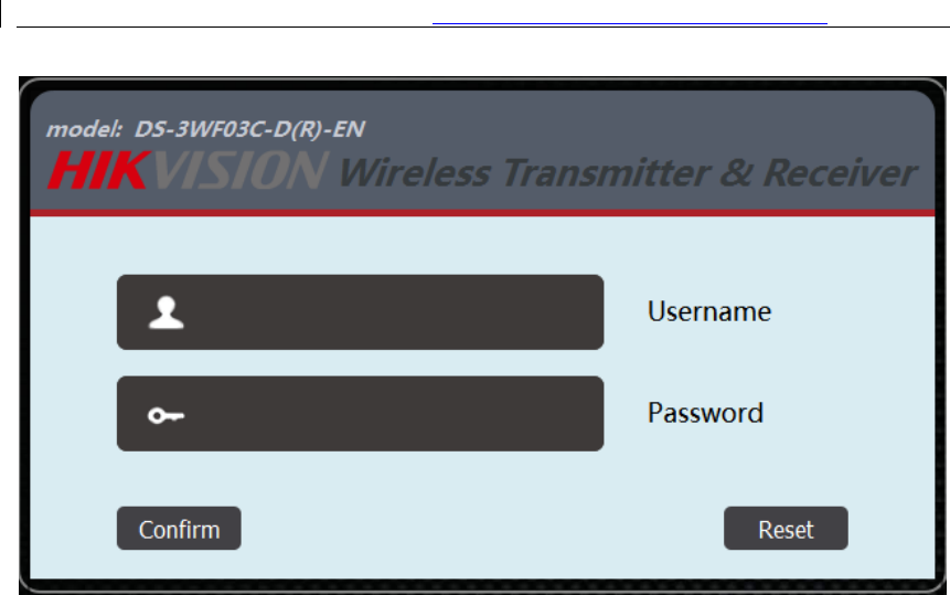
When the above IP setting is done, input the default IP 192.168.1.35 into the
address bar of your web browser, and the following log in interface appears as
shown in figure.
5.
In figure, input the user name and password (default is admin/12345) and click the
Confirm button, then you can log in to the web configuration menu of the DS-
3WF03C-D device.
User Manual of DS-3WF03C-D Outdoor Video Wireless Network Bridge
16
Figure 3-3 DS-3WF03C-D Log in interface
3.2
Quick Configuration of the Device
The users will see how to configure the DS-3WF03C-D device quickly in this chapter.
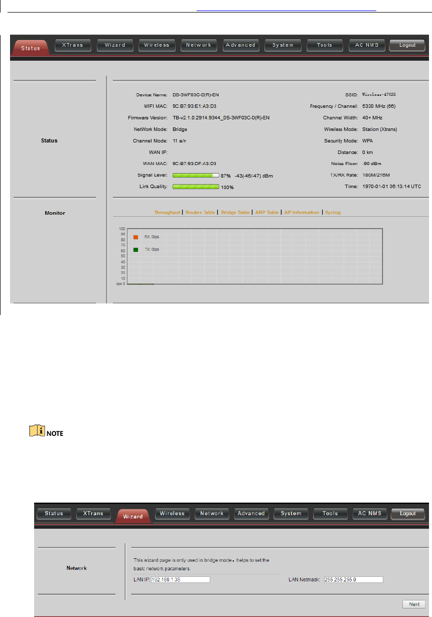
1.
The first page shown after log in is the Status page, which indicates the working
status, current setting, software version and other information of the DS-3WF03C-D
device. Users can switch to other pages by clicking the left main menus in figure.
User Manual of DS-3WF03C-D Outdoor Video Wireless Network Bridge
17
Figure 3-4 Status Page
2.
Click Wizard main menu, the users can configure the device quickly, including
Network and Wireless settings and so on. It is Wizard-Network page as shown in
figure, and this page helps to set the basic network parameters. The default mode is
Bridge mode, and the default LAN IP address is 192.168.1.35. If the user wants to
configure the device to Router mode, please click Network in the main menu.
If several DS-3WF03C-D devices are connected in the Point-to-Point or Point-to-
Multi-Point topologies, they must be configured to different IP address to avoid
collisions.
.
User Manual of DS-3WF03C-D Outdoor Video Wireless Network Bridge
18
Figure 3-5 Wizard Network
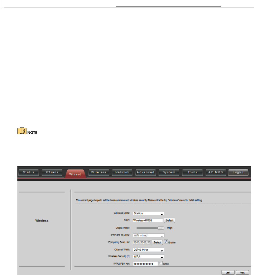
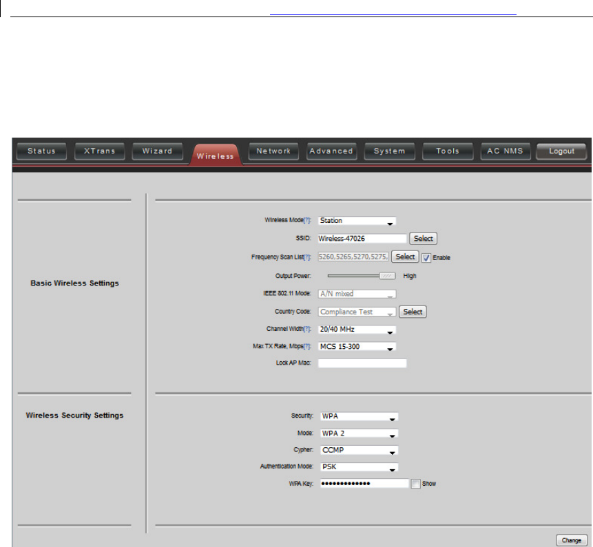
3.
After finishing the Wizard-Network settings, click next and it goes to Wizard-
Wireless page shown in figure. The most used wireless mode is the Access Point and
the Station.
Station mode: The device acts as a WIFI station, and it can be connected to a
normal home access point or DS-3WF03C-D access point.
Access Point mode: The DS-3WF03C-D device acts as an access point, which allows
normal WIFI stations access. For detail settings of wireless mode, please click
Wireless in the main menu.
If two DS-3WF03C-D devices need to be connected in point-to-point topology, one
of the device need to be configured as Access Point, and the other one need to be
configured as Station, and both of them should have the same Encryption method.
Figure 3-6 Wizard Wireless
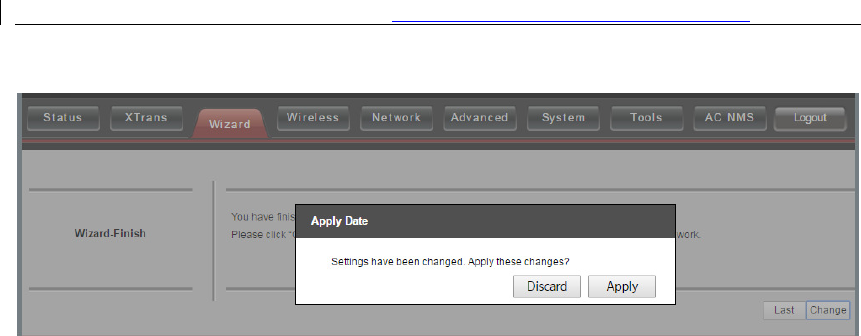
4.
The last page of Wizard is shown in figure. User can click Change to save all the
settings, and then click Apply the make the setting effective, or click last to modify
the previous settings.
User Manual of DS-3WF03C-D Outdoor Video Wireless Network Bridge
19
Figure 3-7 Wizard Finish
User Manual of DS-3WF03C-D Outdoor Video Wireless Network Bridge
20
Chapter 4 TDMA
Currently, most of the outdoor bridge products are developed based on 802.11
protocols, however, it has the limitations of short-distance, hidden node problems, and
poor point-to-multi-point performance.
XTrans technology is developed and patented by Hikvision, utilizing a series of advanced
technologies such as TDMA, 5M/10M/20M/40MHz bandwidth support, intelligent rate
control, Auto ACK Time-out Adjust, having the advantage of long transmission range,
high date rate and robust transmission.
TDMA technology solves the problems of hidden-node problem in the 802.11 network
infra-structure. 5M/10M/20M/40MHz bandwidth can be flexibly configured by the uses
in different working scenario to achieve the best link quality. Intelligent rate control
algorithm can be adapted to quick channel quality variations, while stabilize the wireless
throughput, thus suitable for long-distance transmission. ACK Time-out Auto Adjust can
automatically detect the distances of the DS-3WF03C-D devices, and adjust the wireless
parameters to achieve the best link quality.
The TDMA setting is shown in the following figure.
Figure 4-1 TDMA Settings
To use the TDMA, the user needs to enable TDMA mode in the AP device, and set a
priority level in the station device. When several stations are connected to one AP,
different stations demand different throughput. If the station demands higher
throughput, its priority level can be set to High, otherwise set to Low. When the stations
demand the same throughput, their priority level can be set to the same level.
When using TDMA mode, the TDMA button need to be enabled at both AP and station
devices in the web-based configuration menu. The devices from other vendors cannot
be connected to DS-3WF03C-D in the TDMA mode.
User Manual of DS-3WF03C-D Outdoor Video Wireless Network Bridge
21
Chapter 5 Status
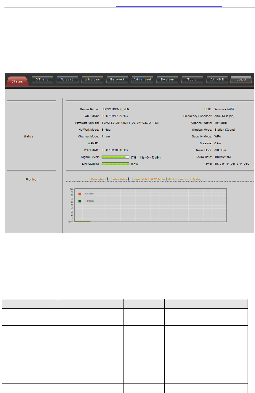
Status is the first page shown after logging in. It shows the current configuration and
real-time monitoring of the device, seen in the following figure. This page is divided into
2 parts: Status and Monitor.
Figure 5-1 Status
5.1
Status
All the configurations in Status page are shown in table.
Table 5-1 Configurations shown in Status
Items
Description
Items
Description
Device
Na
me of the device
SSID
The name of the wireless
network
WIFI MAC
MAC of the wireless
port
Frequency/Ch
annel
Wireless channel chosen
Firmware Version
Software version
number
Channel
Width
5MHz, 10MHz, 20MHz, 40
-
MHz, 40+ MHz
Network Mode
Network mode: Router
or Bridge
Wireless
Mode
Ac
c
ess Point, Station
,
WDS
Access Point, WDS Station,
WDS repeater
Channel
M
ode
Wireless
Security
Wireless encryption method
User Manual of DS-3WF03C-D Outdoor Video Wireless Network Bridge
22
communication
protocol, for example,
11 a/n
Mode
WAN IP
WAN IP address
Distance
The distance between two
associated devices
WAN MAC
MAC of the WAN port
Noise Floor
Noise Floor value
Signal
L
evel
It indicates the signal
strength of the device
T
X
/R
X
Rate
The date rate of
current device
during sending and receiving
data.
Link Quality
Quality of the
connection link
Time
The real
-
time
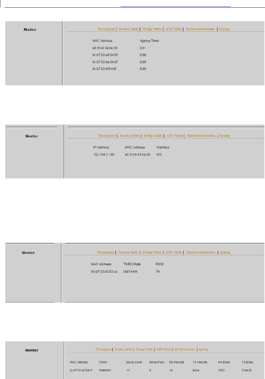
5.2
Monitor
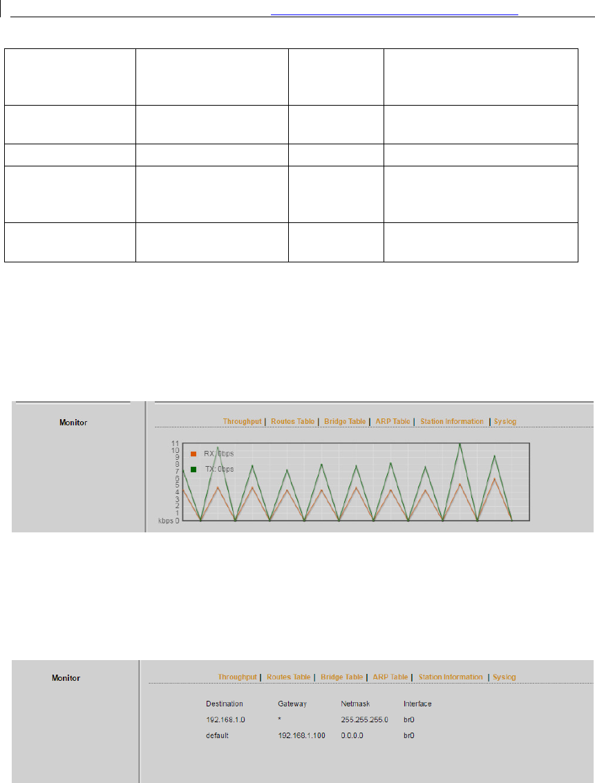
Throughput: The figure here monitors the real-time throughput of the wireless link,
shown in the following figure.
Figure 5-2 Throughput monitor
Routes Table:
It is stored in a router that lists the routes to particular network
destinations, and in some cases, metrics (distances) associated with those routes. The
route table contains information about the topology of the network immediately around
it.
Figure 5-3 Router Table
Bridge Table:
It lists all the devices that communicate through the DS-3WF03C-D device.
User Manual of DS-3WF03C-D Outdoor Video Wireless Network Bridge
23
Figure 5-4 Bridge Table
ARP Table:
It lists the IP address and MAC address of the devices that communicate
through the LAN port of the DS-3WF03C-D device.
Figure 5-5 ARP Table
AP/Station Information:
Showing the status information of the associated devices.
For example, if the DS-3WF03C-D device is an AP, and the associated device is a Station,
and this Station Information shows the related information of the Station device in the
figure.
Figure 5-6 Station Information of an AP
If the DS-3WF03C-D is a Station, and AP Information shows the associated AP device’s
information, seen in figure.
Figure 5-7 AP Information of a Station
Syslog
: Display the log information of DS-3WF03C-D.
User Manual of DS-3WF03C-D Outdoor Video Wireless Network Bridge
24
Chapter 6 Wireless
Wireless is shown in figure.
Figure 6-1 Wireless
Wireless Mode:
There are totally 5 wireless modes, including: Station, Access Point,
WDS Station, WDS Access Point, and WDS Repeater.
Access Point:
Access point.
Station
: A client device that can be connected to an AP.
WDS Station:
Use WDS feature to link multiple APs in a network, all associated stations
from any AP can communicate with each other like in ad-hoc mode. WDS station means
this device is a station in WDS mode.
WDS Access Point
: Use WDS feature to link multiple APs in a network, all associated
stations from any AP can communicate with each other like in ad-hoc mode. WDS AP
means this device is an AP in WDS mode.
WDS Repeater:
A DS-3WF03C-D device can be configured to WDS Repeater mode, so
that it can connected to another WDS Station or WDS Repeater.

User Manual of DS-3WF03C-D Outdoor Video Wireless Network Bridge
25
SSID: Name of a wireless network.
Shown in figure, the user can click the Select button to list all the SSIDs that can be
associated, and then choose the one need to be associated.
Frequency MHz: This only appears when the device is configured to Access Point mode
or WDS Access Point mode. The device can only work on one channel at the same time.
Frequency scan list: This only appears when the device is configured to Station mode or
WDS Station mode. If it’s not enabled, the station will scan all the channels which both
the device and the country code allowed and then choose the same channel as the
associated AP. If it’s enabled, click select, another window will pop up and let the user to
choose the working channels, and the channels should include the associated AP’s
channel, which can fasten the association process between the AP and the Station.
Output Power: Output power of the device.
Country Code: Different countries allows different channels, use can choose the country
code to only allow the device works at the channels permitted in the particular country.
Channel Width: Channel width selection, and DS-3WF03C-D device supports
5MHz/10MHz/20MHz/40MHz bandwidth.
Max TX Rate: Max transmission rate, and it can be used to limit the max transmission
rate of a device.
Root AP MAC Address: In Station, WDS Station, and WDS Repeater modes, users can
use this to limit the APs associated to.
Security: User can set the security based on needs to guarantee the wireless security.
WPA: Encryption method supported by 802.11 Protocol.
User Manual of DS-3WF03C-D Outdoor Video Wireless Network Bridge
26
Chapter 7 Network
7.1
Router Mode
DS-3WF03C-D acts as a router when configured to Router mode. In router mode, the
connection is shown in figure. User needs to connect the POE port of POE adaptor to the
POE port of the DS-3WF03C-D.
After the above connection, the DS-3WF03C-D can work as a router. The LAN2 port of
DS-3WF03C-D device acts as the LAN port of the router, and LAN port of POE adaptor
acts as the WAN port of the router.
Figure 7-1 Connection figure of router mode
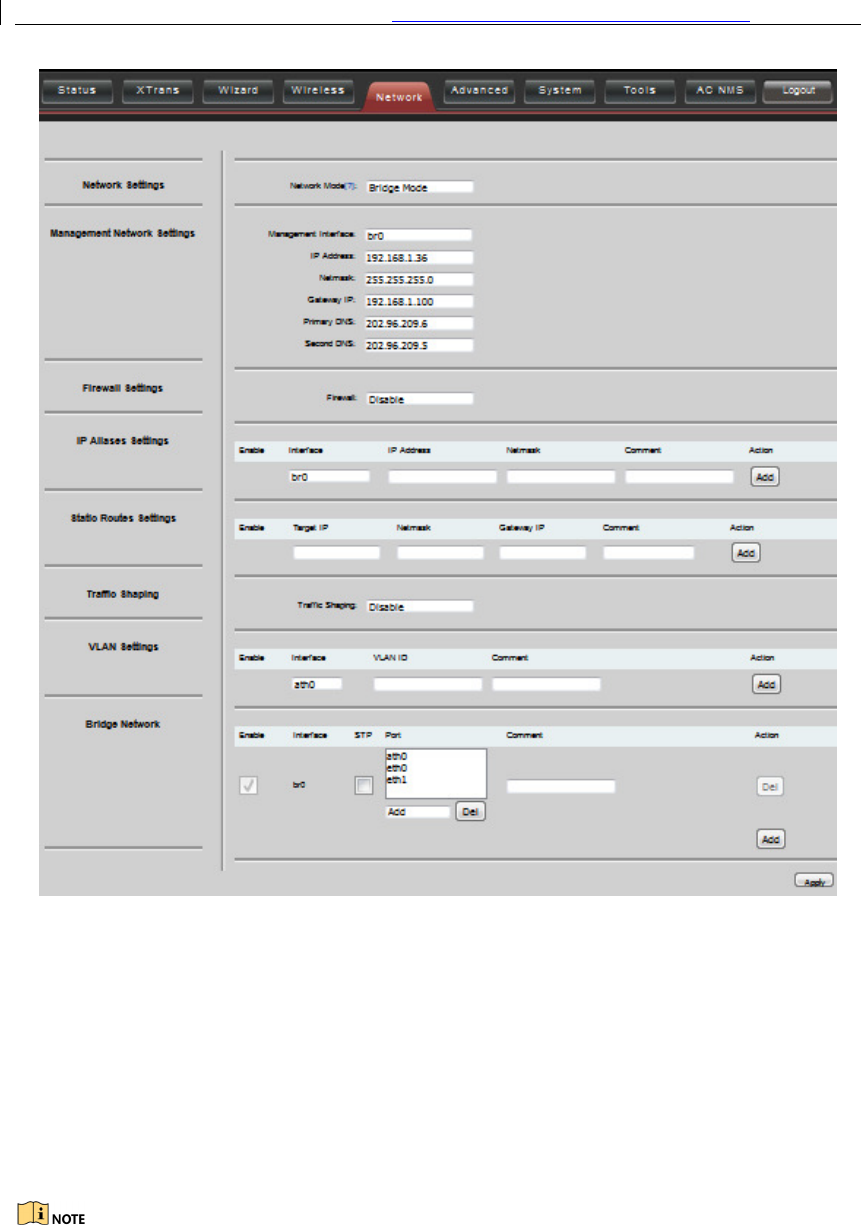
The Network page is shown in figure.
User Manual of DS-3WF03C-D Outdoor Video Wireless Network Bridge
27
Figure 7-2 Router mode
WAN Mode:
WAN mode can be configured to DHCP, PPPoE and Static IP. When set to
DHCP, the device can dynamically get the IP address; otherwise, user needs to manually
set the IP address, Netmask, Gateway and other information.
WAN IP
: WAN IP address. It should be set to the same segment of IP address of the
internet provided by ISP, please check with the ISP for this information.
WAN Netmask
: WAN Netmask, use can check with the ISP for this information.
WAN IP address should not be the same as the IP devices of the internet to avoid
collision.
User Manual of DS-3WF03C-D Outdoor Video Wireless Network Bridge
28
Primary DNS and Secondary DNS: Please check with the ISP for the information.
Gateway IP:
The IP address of WAN gateway.
7.2
Bridge Mode
In Bridge mode, there is no WAN port. The LAN port of the POE adaptor, and the LAN2
port of the DS-3WF03C-D device can all be the LAN port, and the user can choose one of
them to use as LAN port. Please refer to figure for the connections in Bridge mode, and
the IP address/Netmask information setting is the same as Router mode.
7.3
Management
The IP address of the device can be modified, and the management of the device can be
performed by setting the specified management interface.
7.4
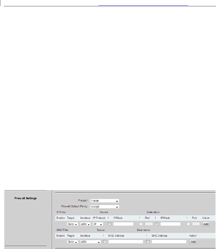
Firewall
When the firewall is enabled, the device can allow only some devices to be associated to.
Shown in figure, and there are 4 cases of Firewall filtering.
Figure 7-3 Firewall
1.
Accept one or several devices with particular MAC address.
2.
Deny one or several devices with particular MAC address.
3.
Accept one or several devices with particular IP address.
4.
Deny one or several devices with particular IP address.

User Manual of DS-3WF03C-D Outdoor Video Wireless Network Bridge
29
7.5
IP Aliases
Add multiple IP to a network interface.
7.6
Static Routes
This feature can be used to set static routing.
7.7
Traffic Shaping
Traffic shaping is used to control the traffic of ingress/egress based on each network
port. As show below, the ingress of ath0 is limited to 1024Kbps, and the egress is limited
to 2048Kbps. That means the receiving rate of the wireless link is limited within 1Mbps,
the sending rate is limited to less than 2Mbps. But usually, the input limited effect is not
obviously, that’s because we could not control how quickly the traffic arrives. However,
when a port sends out egress traffic, it can control how quickly the traffic exits.
Burst defines the how many bytes allowed for downloading/uploading during a short
time. That leads to momentary throughput can greater than the limit value.
Figure 7-4 Traffic Shaping
Ingress traffic entering ath0, control the input rate
Egress traffic exiting ath0, control the output rate
The relationship of rate and burst for ingress:
Set burst to 0, the rate of ingress is unlimited
Set burst to about 1/10 of rate limit, the rate curve is stable
Set burst larger than rate limit, the rate curve will hold a high value for a while
then down to stable

User Manual of DS-3WF03C-D Outdoor Video Wireless Network Bridge
30
Below is the table that reflects the relationship between ingress rate limit and burst.
Ingress Throughput when reach stable
Rate Limit(kbps) Burst(Kbytes) Mbps
Description
10000
0
29.587
Unlimited
10000
10
4.286
Stable
10000
100
8.037
Oblique up to stable
10000
1000
8.825
From 9.5 down to stable
10000
10000
8.6
From 28.5 down to stable
10000
40000
8.6
Hold on 10 seconds at 29.6, then
suddenly down to stable
The relationship of rate and burst for egress:
Set burst less than 1/10 of rate limit, the rate curve is stable totally
Set burst larger than rate limit, the rate curve will hold a while at a higher value
then down to stable
Below is the table that reflects the relationship between egress rate limit and burst.
Egress Throughput when reach stable
Rate Limit(kbps) Burst(Kbytes) Mbps
Description
20000
0
18.853
Stable
20000
20
19.021
Stable
20000
200
19.205
Stable
20000
2000
19.437
From 23.5 down to stable
20000
20000
19.2
Hold on 20 seconds at 24.5, then
suddenly down to stable
20000
80000
19.2
Hold on several minutes at 24.5,
then suddenly down to stable
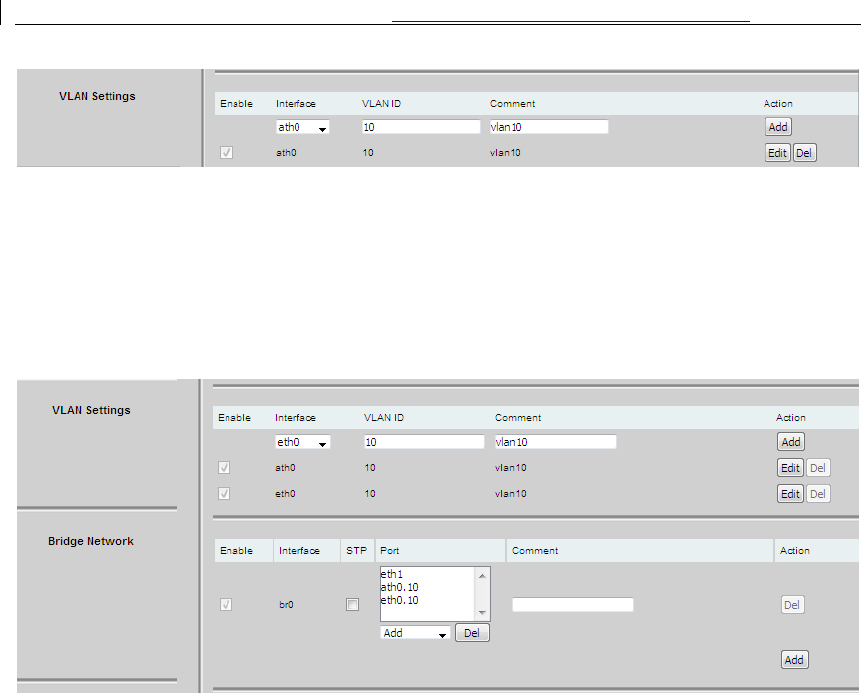
7.8 VLAN Settings
The VLAN function allows user to create multiple virtual local area network. As show
below, we add a VLAN on port ath0. The VLAN ID is 10. The range of VLAN ID is 2~4094.
Each VLAN ID represents a different VLAN.
User Manual of DS-3WF03C-D Outdoor Video Wireless Network Bridge
31
Figure 7-5 VLAN
Bridge function is needed to be used together with VLAN. As show below, we add VLAN
10 on port eth0 and ath0, they are eth0.10 and ath0.10, and put them into the same
bridge. The packets from eth0.10 or ath0.10 will be added a VLAN label which ID is 10.
That requires: the opposite wireless connection side must support VLAN 10, the device
which connects with eth0 is also need to support VLAN 10.
Figure 7-6 VLAN Setting
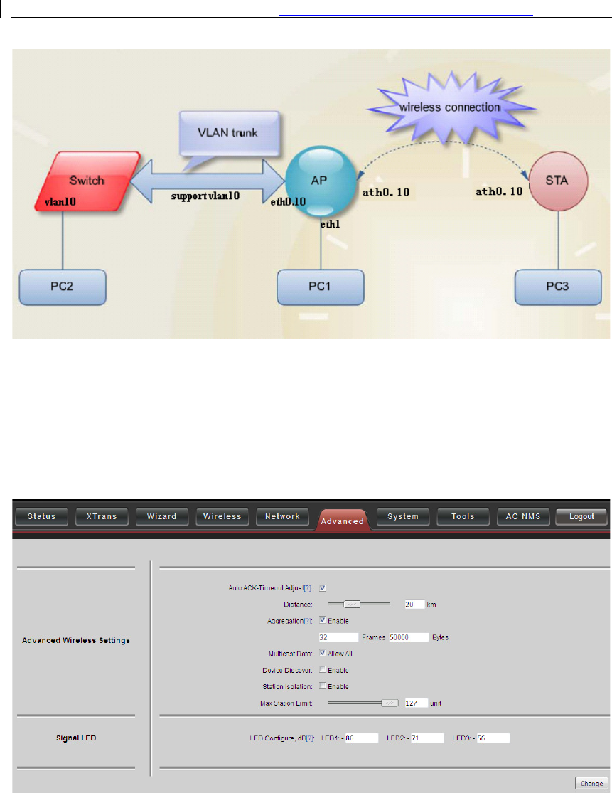
Below is a common usage:
User Manual of
Chapter 8
The Advanced page is shown in
Auto ACK-
Timeout Adjust:
between 2 DS-3WF03C-D
optimized to achieve the best link quality.
User Manual of
DS-3WF03C-D
Outdoor Video Wireless Network
32
Figure 7-7 VLAN Scenarios
Chapter 8
Advanced
The Advanced page is shown in
figure.
Figure 8-1 Advanced
Timeout Adjust:
It is suggested to enable this function, so that the distance
devices can be detected and all the related parameters can be
optimized to achieve the best link quality.
Outdoor Video Wireless Network
Bridge
It is suggested to enable this function, so that the distance
devices can be detected and all the related parameters can be

User Manual of DS-3WF03C-D Outdoor Video Wireless Network Bridge
33
Distance:
The distance can be set manually if the Auto ACK-Timeout Adjust is disabled,
otherwise, the distance parameter is not allowed to be set. It is suggested the distance
is set automatically by enabling Auto ACK-Timeout Adjust parameter.
Aggregation:
It enables several data frames of 802.11 to be aggregated and transmitted
out, thus improve the throughput. In default, it’s enabled.
Multicast Data:
When it’s enabled, DS-3WF03C-D devices allow multicast function.
Device Discover:
This feature should be used with the Hikvision tool. The tool window
will display the MAC address of the device, IP address, and product name and so on.
When the equipment is found by wireless way, please keep multicast support enabled.
Station Isolation:
Enabling this feature can make connection with an access point, the
WDS access points, WDS repeater equipment cannot communicate with each other,
even though the client IP duplicate nor of communication have any impact.
Max Station Limit:
By setting it to limit the number of clients and WDS clients that are
connected to an access point, a WDS access point, a WDS repeater.
LED configure:
This is to configure the signal strength value needed to light on. There
are 3 LEDs on DS-3WF03C-D devices (LED3 value > LED2 value > LED1 value). The default
values are -86dBm, -71dBm and -56dBm. When LED1 value < signal strength < LED2
value, LED1 is lighted on; When LED2 value < signal strength < LED3 value, both the
LED1 and LED2 are lighted on; When signal strength > LED3 value, all three LEDs are
lighted on.
User Manual of DS-3WF03C-D Outdoor Video Wireless Network Bridge
34
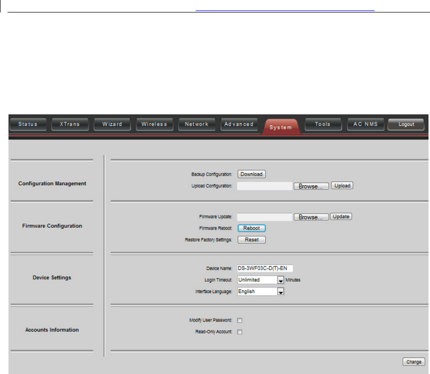
Chapter 9 System
System page is shown in figure, and it is divided into the following 4 parts: Configuration,
Firmware, Device Setting, Accounts.
Figure 9-1 System Page
Backup configuration
: When clicking Download button, the current configuration can be
backed up to a file.
Upload configuration
: When clicking browse, user can choose the backup configuration
file and then click upload, so that the configuration stored in the backup file can be
applied.
Firmware update
: Click browse button and choose the file, and then click update button,
the firmware can be updated to the latest version.
Firmware reboot:
Click the Reboot button to reboot the device.
Restore Factory Settings:
Click the Reset button to restore to the factory default
settings.
Device name:
It can be set to any name needed.
Login Timeout:
Login Timeout setting.

User Manual of DS-3WF03C-D Outdoor Video Wireless Network Bridge
35
Interface Language: Language setting.
Accounts: The user can modify the name and password of user and Read-Only Account.

User Manual of DS-3WF03C-D Outdoor Video Wireless Network Bridge
36
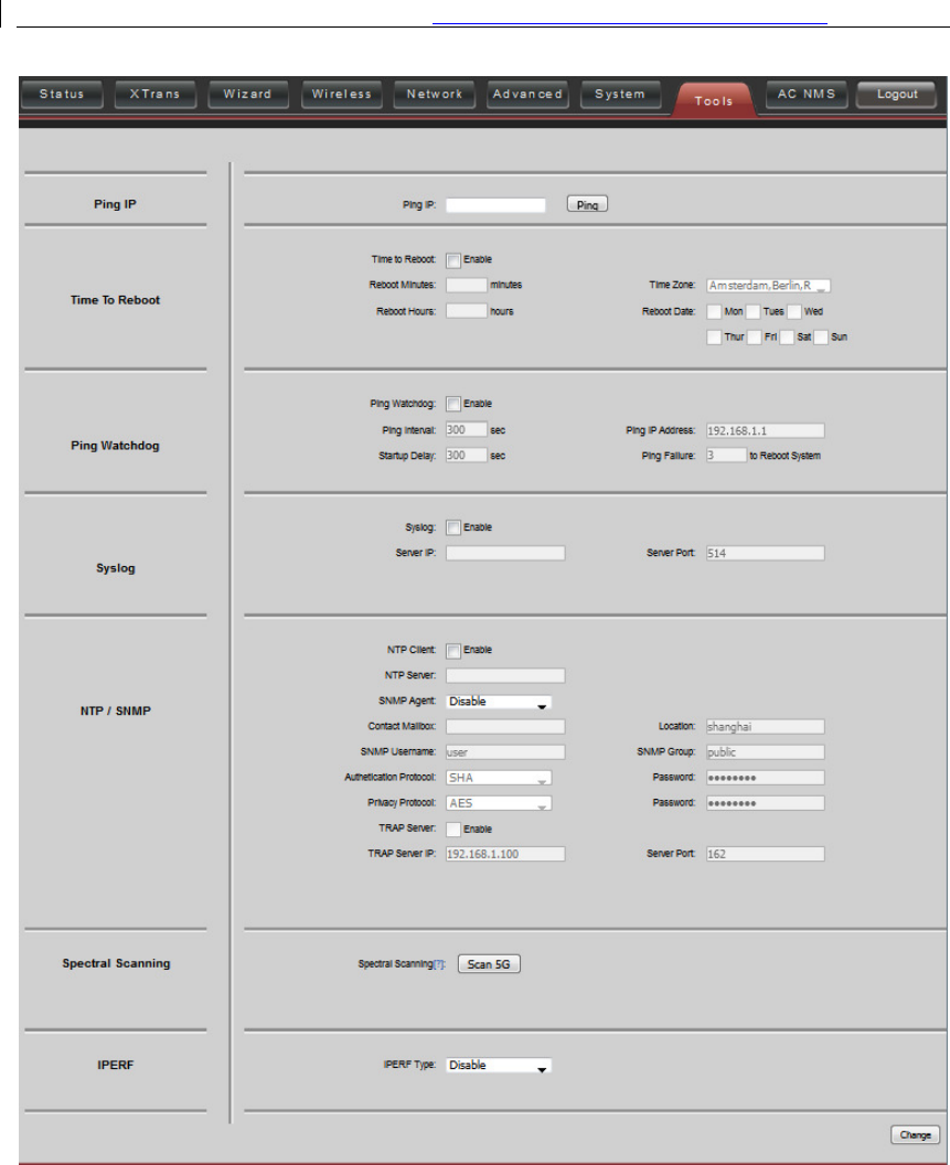
Chapter 10 Tools
The Tools page is shown in figure.
User Manual of DS-3WF03C-D Outdoor Video Wireless Network Bridge
37
Figure 10-1 Tools
Ping IP
: User can input the destination IP address of another device, and click Ping
button. If that destination device is successfully connected to the DS-3WF03C-D device,
the result shows Alive, otherwise shows Not Alive.
Time To Restart
: Timing restart equipment.

User Manual of DS-3WF03C-D Outdoor Video Wireless Network Bridge
38
Ping Watchdog
: The ping watchdog sets the DS-3WF03C-D Device to continuously ping a
user-defined IP address (for example, it can be the IP address of the AP the Client is
connecting to). If it is unable to ping under the user defined constraints, the DS-
3WF03C-D device will automatically reboot. It is highly recommended that users enable
this feature at the side of “Station” and disable this feature at the side of “Access Point”.
Ping Interval:
Specify time interval (in seconds) between the ping requests are sent by
the Ping Watchdog
Ping IP Address:
Specify an IP address of the target which will be monitored by Ping
Watchdog. If this feature is enabled at the side of “Station”, Ping IP Address should be
the IP address of the AP the Client is connecting to.
Startup Delay:
Specify initial time delay (in seconds) until first ping request is sent by the
Ping Watchdog
Ping Failure:
Specify the number of ping replies. If the specified number of ping replies
is not received continuously, the Ping Watchdog will reboot the device.
If users want to modify the parameters of Ping Watchdog, please disable it first and then
apply. When the web page shows that Ping Watchdog is really disabled, users can now
re-enable it with modified parameters.
Telnet/Syslog:
When telnet is enabled, the user can input command “Telnet
192.168.1.36” in the DOS window of Windows XP or Windows 7 PC, and then telnet to
the DS-3WF03C-D and manipulate the DS-3WF03C-D device. When telnet is disabled,
this operation is disabled.
When Syslog is enabled, and the System Log server’s IP is also set here, the log
information will be output to the Syslog server automatically.
NTP/SNMP:
If this NTP server is set, and the DS-3WF03C-D device can access to this NTP
server. DS-3WF03C-D device automatically calibrate the time and date information with
the NTP server and show the time information in the Status page.
When SNMP is enabled, use can check the working condition and information of the DS-
3WF03C-D device.
Spectral Scanning
: Spectral scanning function can view around the 20MHz bandwidth
frequency of the use situation; this can help you configure the device to avoid busy
frequency. If you run the spectral scanning, you cannot do any configuration operations
on the device page. If you want to configure the device again, you only need to click the
exit button in the spectral scanning web page to exit.

User Manual of DS-3WF03C-D Outdoor Video Wireless Network Bridge
39
IPERF: Test equipment throughput. Device 1 select the "server” and the IPERF interval is
the time to display the throughput of the web page. Device 2 select "client" and the
IPERF server to fill in the IP address of the device 1. The number of IPERF threads for
testing the number of threads running at the same time, it is recommended to set up 10.
IPERF test time for running IPERF seconds. IPERF interval time is the time for the display
of the throughput of the web page. For testing, please click the "Test" button.
User Manual of DS-3WF03C-D Outdoor Video Wireless Network Bridge
40
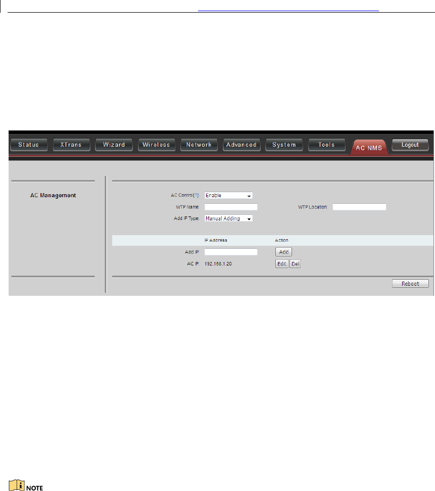
Chapter 11 AC Management
AC Management page is shown in figure. After this function is enabled, the AC
management system must be use
d.
Figure 11-1 AC Management
WTP Name
: It’s the name of the device that is displayed on the AC.
WTP Location:
It’s the location information that is displayed on the AC.
AC IP
: This IP address can add up to eight, add the IP address is AC management
interface’s IP and equipment is the same segment. After the AC control function is
enabled, click save, application, this time the device will take effect on the AC
configuration and restart, the device will join AC. After the AC control function is
enabled, the user is able to display the current state of the page on the device page.
After the AC control function is disabled, the user is able to modify the device's page.
The client must be able to join the AC after it is connected to an access point that has
been joined to the AC.

User Manual of DS-3WF03C-D Outdoor Video Wireless Network Bridge
41
Chapter 12 Logout
When you click logout button, the web will quit and return to the login web.
User Manual of
Chapter 13
Examples
13.1
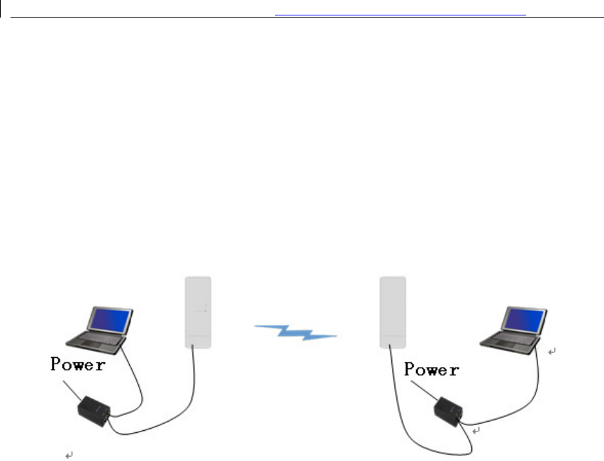
AP and Station Network
In the point-to-
point working scenario, user can configure one
AP, and another to station mode, shown in
To make the above network work, user need to use computers to configure the 2
devices, and the detail configurations are described in the following:
1
Configure the 2 DS-
3WF03C
set different LAN IP for the 2 devices.
2
In wireless menu, configure the 2 devices to AP and station sep
SSID, the same channel bandwidth (20MHz for default), and set the same
encryption and password for both of the devices.
3
After the above setting is done, using one computer to ping the IP address of the
other computer, if they are con
Status page.
User Manual of
DS-3WF03C-D
Outdoor Video Wireless Network
42
Chapter 13
Network Configuration
Examples
AP and Station Network
point working scenario, user can configure one
DS-
3WF03C
AP, and another to station mode, shown in
figure.
Figure 13-1 AP and Station network
To make the above network work, user need to use computers to configure the 2
devices, and the detail configurations are described in the following:
3WF03C
-D
devices to bridge mode, and disable the firewall, and
set different LAN IP for the 2 devices.
In wireless menu, configure the 2 devices to AP and station sep
arately, set the same
SSID, the same channel bandwidth (20MHz for default), and set the same
encryption and password for both of the devices.
After the above setting is done, using one computer to ping the IP address of the
other computer, if they are con
nected, user can watch the connection status in the
Outdoor Video Wireless Network
Bridge
Network Configuration
3WF03C
-D device to
To make the above network work, user need to use computers to configure the 2
devices to bridge mode, and disable the firewall, and
arately, set the same
SSID, the same channel bandwidth (20MHz for default), and set the same
After the above setting is done, using one computer to ping the IP address of the
nected, user can watch the connection status in the

User Manual of DS-3WF03C-D Outdoor Video Wireless Network Bridge
43
Chapter 14 Appendix-A
Troubleshooting
1. The device cannot be started after power on.
1) The Ethernet cable between the DS-3WF03C-D device and the POE adaptor is more
than 40 meters long.
2) The Ethernet cable quality is not good enough, and it should be Cat 5e or even Cat 6
cable.
3) The RJ-45 plugs are not well connected.
2. Cannot be restored to the factory setting
Please manually push the Reset button for 5~10 seconds until all LEDs are light on, then
the user can log in the device by typing the default IP address
192.168.1.36/192.168.1.35.
3. My computer cannot be connected to the DS-3WF03C-D Access Point.
Please try the following method to solve the problem:
1) Adjust the direction of the DS-3WF03C-D device.
Please rotate the DS-3WF03C-D device since the antenna inside the device is
directional.
2) Switch to other wireless channel
Switch to other wireless channel cause there are much interferences in this
channel.
3) Turn off the other interference sources
Maybe there are other WIFI devices nearby and cause interferences. Try to turn off
other WIFI devices nearby, or move DS-3WF03C-D to another clean environment.
4. The signal strength between 2 DS-3WF03C-D devices is too weak, and
throughput is low.

User Manual of DS-3WF03C-D Outdoor Video Wireless Network Bridge
44
1) The DS-3WF03C-D AP and Station devices are not Line-of-Sight, or there are blocks
like a building in between the AP and Station devices.
2) The Station device and AP device is not aligned very well, including both
horizontally and vertically, since the antenna of the DS-3WF03C-D is directional.
3) The Station device is installed in the windows, and the windows glass shields the
wireless signal.
4) The distance between the AP and Station devices is too far.
5. The signal strength is high, but the throughput is low
1) There are too much interferences, or multi-path interferences. For example, there
are too much 2.4GHz or 5.8GHz WIFI device working nearby.
2) The RJ45 ports of the DS-3WF03C-D device don’t work well.
6. During the point-to-point or point-to-multi-point connection, when
ping from one device to another, the latency is too long or the packet is
lost.
1) Isolate the several APs if they are connected to one POE switch.
2) The RJ45 ports are not connected very well.
7. The internet access is lost and the internet speed is low.
1) There are too much stations connected to one AP.
2) AP signal is too weak.
3) There are interference sources nearby.
4) Check the number of users and the max internet speed provided by the ISP.

45