Hangzhou Tuya Information Technology TYZS1 Tuya Zigbee Module User Manual TYZS1 EN Datasheet V1 0 0
Hangzhou Tuya Information Technology Co.,Ltd Tuya Zigbee Module TYZS1 EN Datasheet V1 0 0
User Manual
TYZS1DATASHEET
Tuya Zigbee Module
1. Product Overview
TYZS1 is a low power consumption module with built-in Zigbee connectivity
solution designed by Hangzhou Tuya Information Technology Co., Ltd. The Zigbee Module
consists of a highly integrated wireless radio chip EFR32MG1B132 and some extra
component that has been programed with Zigbee network protocol 802.15.4 PHY/MAC and
plenty of software examples. TYZS1 include a 32-bit ARM Cortex-M4 CPU, 256K byte
flash, 32k SRAM and various peripheral resources.
TYZS1 is a FreeRTOS platform, embedded with all the Zigbee MAC and TCP/IP protocol
function examples, users can customize their Zigbee product by using these software examples.
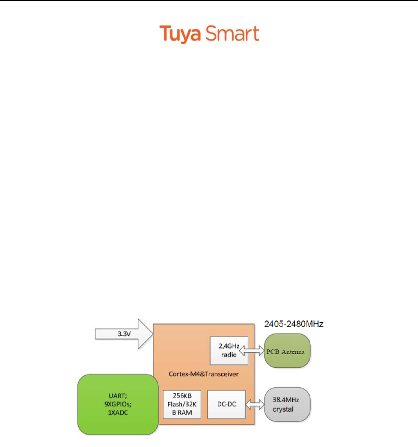
Figure 1 shows the block diagram of the TYZS1.
Figure 1. The block diagram of the TYZS1
1.1 Features
Integrated low power consumption 32-bit ARM Cortex-M4 CPU, with DSP command and
float computing unit also using for application processor
Basic frequency of the CPU can support 40MHz
Supply voltage : DC3.3V
Peripherals: 9 GPIO channels, 1 UART, 1 ADC
Zigbee connectivity:
802.15.4 MAC/PHY
Channel 11 to 26 @ 2.405-2.480 GHz, radio rate 250 kbps
Embedded DC-DC circuit, maximally improving power efficiency
+9.56dBm output power
1.4uA standby current at 63uA/MHz
Automatic paring for terminals
On-board PCB antenna
Operating temperature range: -40℃ to 85℃
Hardware encryption, AES 128/256

TYZS1DATASHEET
1.2 Main Application Fields
Intelligent Building
Intelligent home, Intelligent household applications
Smart socket, smart lighting
Industrial wireless control
Health and measurement management
Asset trace
TYZS1DATASHEET
2. Dimensions and Footprint
2.1 Dimensions
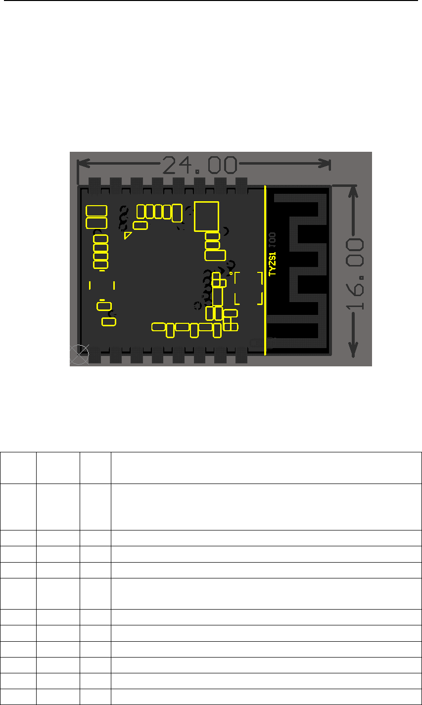
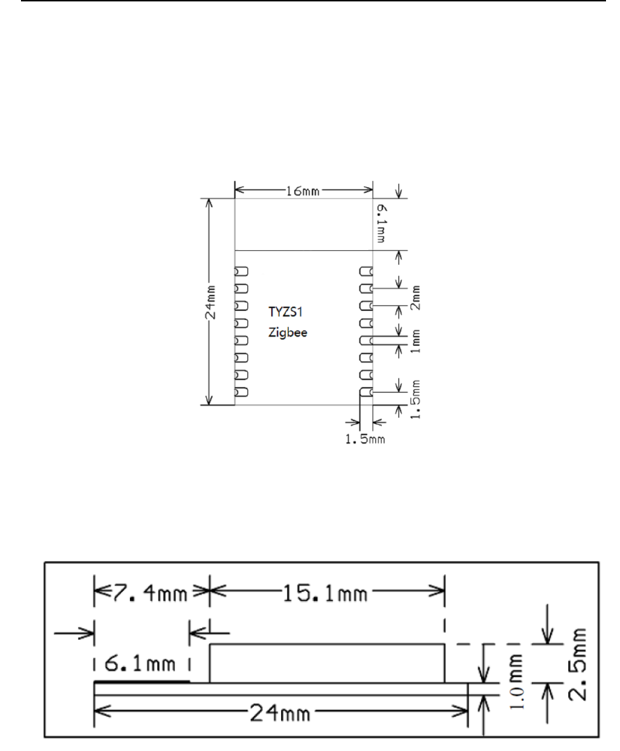
TYZS1 has 2 columns of Pins. The distance between each Pin is 2mm.
Size of TYZS1: 16mm(W)*24mm(L)*3.5mm(H)
Figure 2 shows the dimensions of TYZS1.
Figure 2. The dimensions of TYZS1
2.2 Pin Definition
Table 1 shows the general pin attributes of TYZS1
Table 1. The typical pin definition of TYZS1
PIN
NO.
NAMETYP
E
DISCREPTION
1nRSTIhardwareresetpin,lowleveleffects;
themodulewillresetwhilebooting,usercouldignorethepinjustin
case
2ADCAIADCterminal(12‐bitsSARADC)(1)
3NC‐ NC
4GPIO0I/OGPIO0
5SWOI/OalsousedforuniversalGPIO,canbeusedforoutputpinwhileinJLINK
communicationstatus
6PWM3I/OalsousedforuniversalGPIO
7PWM1I/OalsousedforuniversalGPIO
8VCCPSupplyvoltage(3.3V)
9GNDPGround
10GPIO2I/OalsousedforuniversalGPIO
11SWDIOI/OJLINKSWDIOburningpin,alsousedforuniversalGPIO

TYZS1DATASHEET
12SWCLKI/OJLINKSWCLKburningpin,alsousedforuniversalGPIO
13PWM2I/OalsousedforuniversalGPIO
14GPIO3I/OalsousedforuniversalGPIO
15RXDI/OUART0_RXD
16TXDOUART0_TXD
Note: S: Power supply pins; I/O: Digital input or output pins; AI: Analog input. RST pin is
the module hardware reset pin; it cannot eliminate Zigbee module pairing information.
(1) This pin can only be used as ADC input, cannot use it as normal I/O. when not using, just
connect nothing. When used as ADC input, the input voltage range is 0~AVDD, can be configured
by firmware.
2.3 Test Pin Definition
Table 2 shows the general test pin definition of TYZS1
Table 2. The general test pin definition of TYZS1
PINNO.SYMBOLTYPEDESCRIPTION
‐ ‐ IUsedformodule’sproductiontest
Note: This test pin is not recommended to use.

TYZS1DATASHEET
3. Electrical Characteristics
3.1 Absolute Maximum Ratings
Table 3. Absolute Maximum Ratings
PARAMETERSDESCRIPTIONMINMAXUNIT
TsStoragetemperature‐50150℃
VCCSupplyvoltage 3.8V
Staticelectricityvoltage
(humanmodel)
TAMB‐25℃‐ 2.5KV
Staticelectricityvoltage
(machinemodel)
TAMB‐25℃‐ 0.5KV
3.2 Electrical Conditions
Table 4. Electrical Conditions
PARAMETERSDESCRIPTIONMINTYPICAL MAXUNIT
TaWorkingtemperature ‐40 ‐85℃
VCCWorkingvoltage3.03.33.8V
VILIOlowlevelinput ‐0.3‐ VCC*0.25V
VIHIOhighlevelinputVCC*0.75 ‐ VCCV
VOLIOlowleveloutput ‐‐VCC*0.1V
VoHIOhighleveloutputVCC*0.8‐ VCCV
ImaxIOdrivecurrent ‐‐12mA
3.3 Zigbee Transmitting Current Consumptions
Table 5. Zigbee TX current consumption
PARAMETERSRATETransmittingpowerTYPICAL UNIT
IRF250kbps+9.56dBm32mA
IRF250kbps+9.55dBm17mA
IRF250kbps+7.10dBm11.8mA
Note: continuously transmitting data while testing the result shown above, duty cycle=100%
3.4 Zigbee Receiving Current Consumptions
Table 6. Zigbee RX current consumption
PARAMETERSRATETYPICALUNIT
IRF250kbps8mA
Note: Receiving current 14mA while in active mode.
3.0

TYZS1DATASHEET
3.5 Working Mode Current Consumptions
Table 7. The module working current consumption
WORKMODEAT TA= 25 ℃TYPICALMAX*UNIT
Quickpairing
Mode
TYZS1isunderquickparingmodewith
Gateway.
1040mA
Connection
Mode
TYZS1isconnected0.0051mA
Deepsleep
Mode
TYZS1isindeepsleepmode,reserving64KB
flash
1.43uA
4. WLAN Radio Specification
4.1 Basic Radio Frequency Characteristics
Table 8. Basic Radio frequency characteristics
PARAMETERSDESCRIPTION
Frequencyband2.405GHzto2.480GHz
ZigbeestandardIEEE802.15.4
Datatransmittingrate250kbps
AntennatypeOn‐boardPCBAntenna
Visibletransmittingdistance >120m
4.2 Zigbee Transmitting Power
Table 9. Zigbee transmitting power
PARAMETERSMIN TYPICAL MAXUNI
T
Maximumoutputpower ‐
+9.56
‐dBm
Minimumoutputpower ‐dBm
Outputpoweradjuststep ‐0.51dB
TheFrequencyerror ‐15‐+15ppm
Outputfrequencyadjacentchannelsuppression ‐31 dBc
Note: If more coverage expansion needed, it’s recommended to use TYZS3 module, the
module has pin definition compatible with TYZS1 but with higher penetration performance.
4.3 Zigbee Receiving Sensitivity
Table 9. Zigbee Receiving sensitivity
+7.10
‐

TYZS1DATASHEET
PARAMETERSMIN TYPICAL MAXUNIT
PER<10%,Receivingsensitivity,250kbps@OQPSK‐ ‐102‐dBm

TYZS1DATASHEET
5. Antenna Information
5.1 Antenna Type
Antenna
default connected using
On-board PCB antenna
5.2 Reduce Antenna Interference
While using the On-board PCB antenna, in order to have the best Zigbee performance, it’s
recommended to keep a minimum 15mm distance between the antenna part and the other metal
pieces.
User’s own PCBA design is recommended NOT to pass any wire, NOT do copper pour under
the region of the module’s antenna, to avoid interferences.
TYZS1DATASHEET
6. Packaging Information And Production Guide
6.1 Mechanical Dimensions
Figure 3. Top view of the module
Figure 4. The module’s mechanical view
6.2 PCB Recommended Package
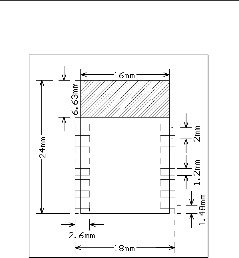
TYZS1DATASHEET
Figure 5. PCB Package Drawing
TYZS1DATASHEET
6.3 Production Guide
The storage for the delivered module should meet the following condition:
1. The anti-moisture bag should be kept in the environment with temperature < 30℃ and
humidity < 85% RH.
2. The expiration date is 6 months since the dry packaging products was sealed.
Cautions:
1. All the operators should wear electrostatic ring in the whole process of production.
2. While operating, water and dirt should not have any contact with the modules.
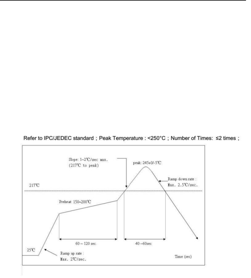
6.4 Recommended furnace temperature curve
Figure 6. PCB Package DrawingRecommended furnace temperature curve
FCC Statement:
Any Changes or modifications not expressly approved by the party responsible for compliance could void
the user’s authority to operate the equipment.
This device complies with part 15 of the FCC Rules. Operation is subject to the following two conditions:
(1) This device may not cause harmful interference, and
(2) This device must accept any interference received, including interference that may cause undesired operation.
FCC Radiation Exposure Statement:
This equipment complies with FCC radiation exposure limits set forth for an uncontrolled environment .This
equipment should be installed and operated with minimum distance 20cm between the radiator& your body.
FCC Label Instructions:
The outside of final products that contains this module device must display a label
referring to the enclosed module. This exterior label can use wording such as: “Contains
Transmitter Module FCC ID:2ANDL-TYZS1”,or “Contains FCC ID:2ANDL-TYZS1”, Any
similar wording that expresses the same meaning may be used.