Hans Turck and KG TNSLRQ350 RFID Reader User Manual
Hans Turck GmbH & Co. KG RFID Reader
Contents
- 1. user manual
- 2. user manual annex
user manual

USER-
MANUAL
RFID SYSTEM
INSTALLATION
OF THE
BL IDENT-
SYSTEM
S1583/ 01
D101583 0207
BL ident
2

D101583 0207 BL ident 3
Safety Instructions!
Before beginning installation work
Disconnect the device from the power supply
Ensure against accidental restart
Verify isolation from the supply
Cover or close off neighbouring units that are live.
The assembly instructions provided for the device are to be
complied with
Only suitably qualified personnel according to EN 50 110-1/-2
(VDE 0105 part 100) are authorised to carry out work on this
device/system.
When conducting installation work ensure that you are free of
electrostatic charge before touching the device.
Connection and signal cables are to be installed so that any
inductive or capacitive interference does not impair the
automation functions.
The installation of automation devices and their operating
elements is to be carried out in such a way as to prevent
unintentional operation.
In order to prevent cable or wire breakage on the signal side
generating undefined states in the automation devices,
appropriate safety measures are to be taken for the I/O coupling
on the hardware and software side.
The functional earth (FE) must be connected to the protective
earth (PE) or the equipotential bonding. The system installer is
responsible for establishing this connection.
Ensure a reliable isolation of the extra-low voltage for the 24 volt
supply. Only those power supply units that comply with IEC 60
364-4-41, i.e. HD 384.4.41 S2 (VDE 0100 part 410) are to be
deployed.
Fluctuations or deviations of the mains voltage from the nominal
value should not exceed the tolerance limits specified in the
technical data, otherwise malfunctions and dangerous states
may occur.
D101583 0207 BL ident4
Devices for mounting in housings or cabinets, desktop or
portable units, are only to be operated and controlled with the
housing closed.
Measures are to be taken to ensure the correct restarting of a
program following interruption due to a voltage drop or failure.
Dangerous operating conditions, even short term, should not
occur as a result. If required an emergency stop should be
carried out.
External measures are to be implemented at those locations
where faults in the automation installation could lead to injury to
persons or damage to property. These measures must
guarantee safe operating conditions even in the event of a fault
or malfunction (e.g. by means of independent limit switches or
mechanical locking devices etc.).
The electrical installation must be carried out in accordance with
the relevant regulations (e.g. in respect of the cable cross
sections,
fuses and protective earth connections).
All work involving transport, installation, commissioning and
maintenance is to be carried out exclusively by qualified
personnel (in accordance with IEC 60 364 i.e. HD 384 or
DIN VDE 0100 and national accident prevention regulations).
USA Radio Frequency Interference FCC Part 15 Notice:
Changes or modifications not expressly approved by TURCK
could void the user's authority to operate the equipment

5
Contents
D101583 0207 BL ident
Contents
About this manual
Documentation concept..............................................................................0 – 2
Description of symbols used ......................................................................0 – 4
Prescribed use ......................................................................................0 – 5
Notes concerning planning / Installation of this product ......................0 – 5
1 The TURCK BL ident System – Overview
Schematic representation of the identification system BL ident ................1 – 2
Support for BL ident-projects ...............................................................1 – 2
Networking with BL ident systems........................................................1 – 3
Identification systems with radio frequency technology (RFID)..................1 – 4
Characteristics and fields of application of the BL identsystem.................1 – 5
Degree of protection .............................................................................1 – 5
Service life.............................................................................................1 – 5
Transmission frequency........................................................................1 – 5
Size........................................................................................................1 – 6
Read/write time.....................................................................................1 – 6
Compatibility .........................................................................................1 – 7
Areas of application (examples) ............................................................1 – 7
The BL ident-configurator .....................................................................1 – 8
2 TURCK BL ident System – Planning
Selection criteria for data carriers and read-write head..............................2 – 2
Transfer zone and read-write distance.......................................................2 – 3
Length of the transfer zone and width offset..............................................2 – 4
Minimum distance of the data carriers to read-write head,
influence of adjacent fields .........................................................................2 – 4
Permissible direction of movement of the data carrier...............................2 – 4
Reading and writing in static operation ......................................................2 – 4
Reading and writing in dynamic operation (on the fly)................................2 – 5
Dwell time of the data carrier Td..................................................................2 – 5
Calculation of the maximum quantity of user data
in dynamic operation...................................................................................2 – 5
Minimum distances between two adjacent data carriers ...........................2 – 6
Contents
6D101583 0207 BL ident
3 Installation guidelines
Overview.....................................................................................................3 – 2
Reduction of metallic influences.................................................................3 – 2
Installation of several read-write heads on metal frames
or metal supports........................................................................................3 – 3
No mounting of the data carrier directly on metal ......................................3 – 5
Conclusion – influence on the transfer from metal .....................................3 – 5
4 EMC directives
For whom are the EMC directives intended?............................................. 4 – 2
Dispersion of electromagnetic interference................................................4 – 2
How can RFID be subject to interference? ...........................................4 – 3
Coupled interference.............................................................................4 – 3
What does EMC mean?..............................................................................4 – 4
Fundamentals for EMC protection..............................................................4 – 5
Installation in a switch cabinet..............................................................4 – 6
Avoiding sources of interference...........................................................4 – 7
Potential equalization............................................................................4 – 7
Shielding the cable................................................................................4 – 7
5 Description of the data carrier
Type overview.............................................................................................5 – 2
Function principle........................................................................................5 – 3
Technical data
TW-R16-B64...............................................................................................5 – 5
TW-R16-B128.............................................................................................7 – 7
TW-R20-B128.............................................................................................9 – 9
TW-R30-B128...........................................................................................5 – 11
TW-R50-B128...........................................................................................5 – 13
TW-R20-K2...............................................................................................5 – 15
TW-R30-K2...............................................................................................5 – 17
TW-R50-K2...............................................................................................5 – 19
TW-R22-HT-B64.......................................................................................5 – 21

7
Contents
D101583 0207 BL ident
TW-R50-90-HT-B128................................................................................5 – 23
TW-R50-90-HT-K2................................................................................... 5 – 25
TW-I14-B128.............................................................................................5 – 27
TW-L43-43-F-B128...................................................................................5 – 29
TW-L82-49-P-B128 ..................................................................................5 – 31
6 Description of the read-write heads
Type overview.............................................................................................6 – 2
Function principle........................................................................................6 – 3
Technical data
TB-M18-H1147...........................................................................................6 – 6
TB-M18-H1147/S1126 (optimised for special data carriers)......................6 – 7
TB-EM18WD-H1147 (wash-down)..............................................................6 – 8
TB-EM18WD-H1147/S1126 (wash-down, optimised for special
data carriers) ..............................................................................................6 – 9
TN-M18-H1147.........................................................................................6 – 10
TN-M18-H1147/S1126 (optimised for special data carriers)....................6 – 11
TN-EM18WD-H1147 (wash-down) ...........................................................6 – 12
TN-EM18WD-H1147/S1126 (wash-down, optimised for special
data carriers) ............................................................................................6 – 13
TB-M30-H1147.........................................................................................6 – 14
TB-M30-H1147/S1126 (optimised for special data carriers)....................6 – 15
TB-EM30WD-H1147 (wash-down)............................................................6 – 16
TB-EM30WD-H1147/S1126 (wash-down, optimised for special
data carriers) ............................................................................................6 – 17
TN-M30-H1147.........................................................................................6 – 18
TN-M30-H1147/S1126 (optimised for special data carriers)....................6 – 19
TN-EM30WD-H1147 (wash-down) ...........................................................6 – 20
TN-EM30WD-H1147/S1126 (wash-down, optimised for special
data carriers) ............................................................................................6 – 21
TN-CK40-H1147.......................................................................................6 – 22
TN-CK40-H1147/S1126 (optimised for special data carriers)..................6 – 23
Contents
8D101583 0207 BL ident
TN-Q80-H1147 .........................................................................................6 – 24
TN-Q80-H1147/S1126 (optimised for special data carriers) ....................6 – 25
TNER-Q80-H1147 (increased range)........................................................6 – 26
TNLR-Q80-H1147 (long range).................................................................6 – 27
TNLR-Q80-H1147/S1126 (long range, optimised for special
data carriers).............................................................................................6 – 28
TN-S32XL-H1147......................................................................................6 – 29
Connection of the read-write heads .........................................................6 – 30
7 Description of the read-write heads with corresponding data carriers
Notes for the operating data.......................................................................7 – 5
TB-M18-H1147............................................................................................7 – 3
TB-EM18WD-H1147....................................................................................7 – 3
TB-M18-H1147/S1126................................................................................7 – 4
TB-EM18WD-H1147/S1126 ........................................................................7 – 4
TN-M18-H1147............................................................................................7 – 5
TN-EM18WD-H1147....................................................................................7 – 5
TN-M18-H1147/S1126................................................................................7 – 6
TN-EM18WD-H1147/S1126........................................................................7 – 6
TB-M30-H1147............................................................................................7 – 7
TB-EM30WD-H1147....................................................................................7 – 8
TB-M30-H1147/S1126................................................................................7 – 9
TB-EM30WD-H1147/S1126 ......................................................................7 – 10
TN-M30-H1147..........................................................................................7 – 11
TN-EM30WD-H1147..................................................................................7 – 12
TN-M30-H1147/S1126..............................................................................7 – 13
TN-EM30WD-H1147/S1126......................................................................7 – 14
TN-CK40-H1147........................................................................................7 – 15
TN-CK40-H1147/S1126............................................................................7 – 16
TN-Q80-H1147..........................................................................................7 – 17
TN-Q80-H1147/S1126 ..............................................................................7 – 18

9
Contents
D101583 0207 BL ident
TNER-Q80-H1147 .....................................................................................7 – 19
TNLR-Q80-H1147......................................................................................7 – 20
TNLR-Q80-H1147/S1126..........................................................................7 – 21
TN-S32XL-H1147 ......................................................................................7 – 22
8
Overtravel distances of the read-write heads with corresponding data carriers
Notes for the overtravel distances..............................................................8 – 3
Overtravel distance read-write head – housing style M18
TN-M18-H1147 with data carrier TW-R16-…B128 ....................................8 – 4
TB-M18-H1147 with data carrier TW-R16-…B128.....................................8 – 4
TN-M18-H1147 with data carrier TW-R20-…B128 ....................................8 – 5
TB-M18-H1147 with data carrier TW-R20-…B128.....................................8 – 5
TN-M18-H1147 with data carrier TW-R30-…B128 ....................................8 – 6
TB-M18-H1147 with data carrier TW-R30-…B128.....................................8 – 6
TN-M18-H1147 with data carrier TW-R50-…B128 ....................................8 – 7
TN-M18-H1147 with data carrier TW-R20-…K2 ........................................8 – 7
TB-M18-H1147 with data carrier TW-R20-…K2.........................................8 – 8
TN-M18-H1147 with data carrier TW-R30-…K2 ........................................8 – 8
TN-M18-H1147 with data carrier TW-R50-…K2 ........................................8 – 9
Overtravel distance read-write head – housing style M30
TN-M30-H1147 with data carrier TW-R16-…B128 ....................................8 – 9
TB-M30-H1147 with data carrier TW-R16-…B128...................................8 – 10
TN-M30-H1147 with data carrier TW-R20-…B128 ..................................8 – 10
TB-M30-H1147 with data carrier TW-R20-…B128...................................8 – 11
TN-M30-H1147 with data carrier TW-R30-…B128 ..................................8 – 11
TB-M30-H1147 with data carrier TW-R30-…B128...................................8 – 12
TN-M30-H1147 with data carrier TW-R50-…B128 ..................................8 – 12
TB-M30-H1147 with data carrier TW-R50-…B128...................................8 – 13
TN-M30-H1147 with data carrier TW-R20-…K2 ......................................8 – 13
TB-M30-H1147 with data carrier TW-R20-…K2.......................................8 – 14
TN-M30-H1147 with data carrier TW-R30-…K2 ......................................8 – 14
Contents
10 D101583 0207 BL ident
TB-M30-H1147 with data carrier TW-R30-…K2.......................................8 – 15
TN-M30-H1147 with data carrier TW-R50-…K2 ......................................8 – 15
TB-M30-H1147 with data carrier TW-R50-…K2.......................................8 – 16
Overtravel distance read-write head – housing style Q40
TN-CK40-H1147 with data carrier TW-R16-…B128.................................8 – 16
TN-CK40-H1147 with data carrier TW-R20-…B128.................................8 – 17
TN-CK40-H1147 with data carrier TW-R30-…B128.................................8 – 17
TN-CK40-H1147 with data carrier TW-R50-…B128.................................8 – 18
TN-CK40-H1147 with data carrier TW-R20-…K2.....................................8 – 18
TN-CK40-H1147 with data carrier TW-R30-…K2.....................................8 – 19
TN-CK40-H1147 with data carrier TW-R50-…K2.....................................8 – 19
Overtravel distance read-write head – housing style Q80
TN-Q80-H1147 with data carrier TW-R16-…B128...................................8 – 20
TN-Q80-H1147 with data carrier TW-R20-…B128...................................8 – 20
TN-Q80-H1147 with data carrier TW-R30-…B128...................................8 – 21
TN-Q80-H1147 with data carrier TW-R50-…B128...................................8 – 21
TN-Q80-H1147 with data carrier TW-R20-…K2.......................................8 – 22
TN-Q80-H1147 with data carrier TW-R30-…K2.......................................8 – 22
TN-Q80-H1147 with data carrier TW-R50-…K2.......................................8 – 23
Overtravel distance read-write head – housing style S32
TN-S32XL-H1147 with data carrier TW-R16-…B128...............................8 – 23
TN-S32XL-H1147 with data carrier TW-R30-…B128...............................8 – 24
TN-S32XL-H1147 with data carrier TW-R50-…B128...............................8 – 24
TN-S32XL-H1147 with data carrier TW-R30-…K2...................................8 – 25
TN-S32XL-H1147 with data carrier TW-R50-…K2...................................8 – 25
9 Accessories
General description of the accessories.......................................................9 – 2
Accessories for Ø 30 mm and Ø 50 mm data carriers
Spacer DS-R30...........................................................................................9 – 3
Spacer DS-R50...........................................................................................9 – 4

11
Contents
D101583 0207 BL ident
Accessories for read-write heads of housing style M18
Mounting clip BS18.....................................................................................9 – 5
Mounting clip BSN18..................................................................................9 – 6
Mounting clip with limit stop BST-18B .......................................................9 – 7
Mounting clip without limit stop BST-18N..................................................9 – 8
Quick mounting mounts QM-18 .................................................................9 – 9
Cover cap SKN/M18.................................................................................9 – 10
Accessories for cylindrical read-write heads of housing style M30
Mounting clip with limit stop BST-30B. ....................................................9 – 11
Mounting clip without limit stop BST-30N................................................9 – 12
Quick mounting mounts QM-30 ...............................................................9 – 13
Cover cap SKN/M30.................................................................................9 – 14
Common accessories for read-write heads of housing style M18 and M30
Mounting aid for BST mounting clips BST-UH.........................................9 – 15
Mounting aid for BST mounting clips BST-UV .........................................9 – 16
Inscription labels for BST mounting clips BST-BS ...................................9 – 17
Accessories for read-write heads of housing style CK40
Protective mounting MF-CK40-1S............................................................9 – 18
Protective mounting MF-CK40-2S............................................................9 – 19
Protective mounting MF-CK40-3S............................................................9 – 20
Protective housing SG40..........................................................................9 – 21
Protective housing SG40/2, temperature resistant...................................9 – 22
Adjustable rail JS 025/037........................................................................9 – 23
Cover cap T-CK40-T-FC...........................................................................9 – 24
Cover capT-CK40-D-FC, temperature resistant.......................................9 – 25
Handheld with accessories
PD-ident....................................................................................................9 – 26
PD-ident-WLAN ........................................................................................9 – 27
PD-ident-PF..............................................................................................9 – 27
PD-ident-DS..............................................................................................9 – 27
Contents
12 D101583 0207 BL ident
PD-ident-RB..............................................................................................9 – 28
PD-ident-BC..............................................................................................9 – 28
PD-ident-RS..............................................................................................9 – 28
PD-ident-CB..............................................................................................9 – 28

0 – 1
About this manual
D101583 0207 BL ident
About this manual
Documentation concept....................................................................................2
Description of symbols used ............................................................................4
Prescribed use ........................................................................................... 5
Notes concerning planning / Installation of this product ........................... 5
About this manual
0 – 2 D101583 0207 BL ident
Documentation concept
This manual contains all the information necessary for professional
installation of the BL ident systems particularly with regard to the
data carriers and the read-write heads.
The following chapter provides an overview of the BL ident system,
how to plan a BL ident system and indicates the necessary
installation guidelines while providing a brief overview of the EMC
directives. The manual also describes the functional principle of the
data carriers and read-write heads, the technical data and operating
data as well as the available accessories.
The manuals for BL67 and BL20 I/O modules contain information
concerning the non bus-specific I/O modules of the modular TURCK
BL67 and BL20 systems. You can find a short system description, a
detailed function description of the I/O modules as well as all the
information concerning topics such as mounting/dismounting and
inscription. The manuals contain a short description of the I/O-
ASSISTANT which is the engineering and configuration software for
TURCK I/O products.
Manual BL67 I/O Modules
TURCK documentation number:
German D300572/
English D300529
Manual BL20 I/O Modules
TURCK documentation number:
German D300716/
English D300717
Also included are manuals concerning the PROFIBUS-DP and
DeviceNet™ gateway of the BL67 and BL20 series. These include a
short BL67 or BL20 system description and a description of the
PROFIBUS-DP or DeviceNet™ fieldbus systems. Besides you will
find exact details concerning the function and design of bus-specific
gateways as well as all bus-specific information concerning the
connection to different automation devices, the maximum system
extension, etc.
Manual BL67 PROFIBUS-DP
TURCK documentation number:
German D300570/
English D300527

0 – 3
About this manual
D101583 0207 BL ident
Manual BL67 DeviceNet™
TURCK documentation number:
English D300528
Manual BL20 PROFIBUS-DP
TURCK documentation number:
German D300822/
English D300458
Manual BL20 DeviceNet™
TURCK documentation number:
English D300460.
Further support can be found in the following manuals for
engineering, installation and commissioning:
Manual D101580 - This manual describes the professional
application of BL ident interface modules.
Manual D101578 - This manual includes instructions for
commissioning of a BL ident systems using the function block
“Proxy Ident Function Block”. The commissioning example is
undertaken using a SIMATIC S7/-300 station (Siemens).
SIMATIC STEP 7 standard software is used.
Manual D101606 - This manual contains the software
description for the so-called “Handheld” (programming device)
which can be used to read data irrespective of the location.
Manual D101584 - This manual contains the hardware
description for the so-called “Handheld” (programming device)
which can be used to read data irrespective of the location.

About this manual
0 – 4 D101583 0207 BL ident
Description of symbols used
Warning
This sign can be found next to all notes that indicate a source of
hazards. This can refer to danger to personnel or damage to the
system (hardware and software).
This sign means for the operator: work with extreme caution.
Attention
This sign can be found next to all notes that indicate a source of
potential hazards.
This can refer to possible danger to personnel or damage to the
systems (hardware and software) and installations.
Note
This sign can be found next to all general notes that supply
important information about one or more operating stages.
These specific notes are intended to make operation easier and
avoid unnecessary work due to incorrect operation.

0 – 5
About this manual
D101583 0207 BL ident
This manual contains all the necessary information concerning the
intended usage of TURCK products. It has been specially developed
for qualified personnel who have the required level of expertise.
Prescribed use
Appropriate transport, storage deployment and mounting as well as
careful operating and thorough maintenance guarantee trouble-free
and safe operation of these devices.
Notes concerning planning / Installation of this product
Attention
Please read this section carefully. Safety aspects cannot be left to
chance when dealing with electrical equipment
Warning
The devices described in this manual must be used only in
applications prescribed in this manual or in the respective technical
descriptions, and only in connection with components and devices
from third party manufacturers that have been certified.
Warning
It is imperative that all respective safety measures and accident
protection guidelines be adhered to.

About this manual
0 – 6 D101583 0207 BL ident

D101583 0207 BL ident 1 – 1
1
The TURCK BL ident System
1 The TURCK BL ident system
Schematic representation of the identification system BL ident .........................2
Support for BL ident projects......................................................................2
Networking with BL ident systems..............................................................3
Identification systems with radio frequency technology (RFID)........................4
Characteristics and fields of application of the BL ident system......................5
Degree of protection ...................................................................................5
Service life ...................................................................................................5
Transmission frequency ..............................................................................5
Size..............................................................................................................6
Read/write time ...........................................................................................6
Compatibility ...............................................................................................7
Areas of application (examples): .................................................................7
The BL ident configurator .................................................................................8
The TURCK BL ident System
D101583 0207 BL ident1 – 2
Schematic representation of the identification system BL ident
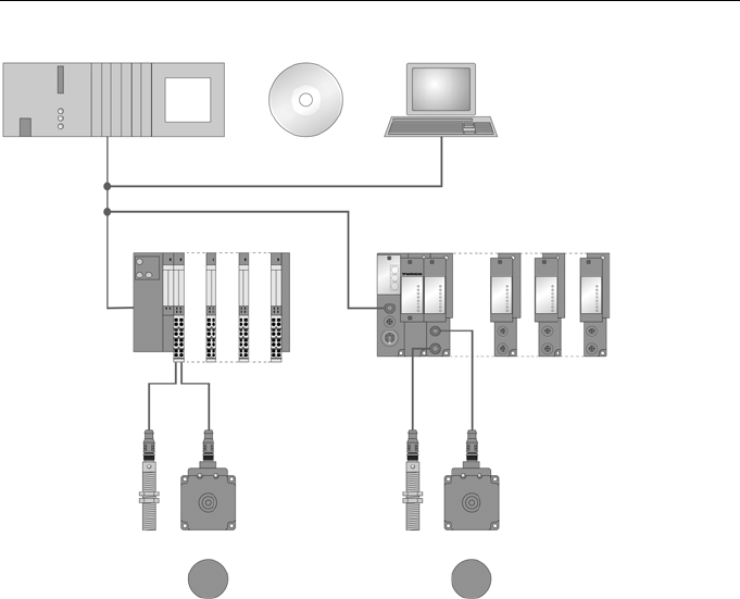
The TURCK BL ident system consists of several levels. Every level
offers variation options. An application adapted to the overall
system is possible.
Support for BL ident projects
Further support can be found in the following software for
engineering, installation and commissioning:
For simulation and optimisation of an application a “BL ident
configurator” is available free of charge on the internet at
www. turck.com (see page 1 - 8).
Figure: 1
System overview
PLC/PC for commissioning
Interface module for integration
in the fieldbus systems
Read/write devices
Mobile data carriers
IP20 IP67

D101583 0207 BL ident 1 – 3
The TURCK BL ident System
1
Networking with BL ident systems
As it is possible to integrate BL ident systems in (existing) bus
systems, networking of several BL ident systems is possible.
The guidelines which relate to the maximum extension of the
respective bus systems apply.
A PROFIBUS system can only extend, for example, up to a
maximum of 31 stations with 1 master when a repeater is not used.
The TURCK BL ident System
D101583 0207 BL ident1 – 4
Identification systems with radio frequency technology (RFID)
RFID is the abbreviation for Radio Frequency Identification.
An RFID system consists of a data carrier, a device for reading the
data from the data carrier (read-write head) as well as other devices
which perform the transfer and processing of data (interfaces).
The transfer of data from the data carrier to the read-write heads is
undertaken using electromagnetic waves. This type of data transfer
is non-contact, without a visual contact and is insensitive to dirt and
temperature fluctuations.
The data carriers can be attached directly to a product. Further
terms used for the data carriers are TAGs or transponders. The data
content can consist of production and manufacturing data.
Important it that this data identifies the product. This is the
origination of the term “Identification System”.
A whole range of possibilities exist as the data content can be
changed by writing on the data carrier. Accordingly, the production
and manufacturing processes can be traced and monitored.
Logistics/distribution can be optimized.
The “Identifications Systems” can be integrated into (existing)
fieldbus systems (e.g. PROFIBUS). The integration of the respective
fieldbus system is undertaken with suitable interfaces.
Standardized software modules (e.g. the Proxy Ident Function Block
for PROFIBUS) enable simple system integration and
commissioning with different controls.

D101583 0207 BL ident 1 – 5
1
The TURCK BL ident System
Characteristics and fields of application of the BL ident system
In order to comply with the demands presented by different fields of
application, TURCK offers the BL ident system with a whole range
of combination possibilities of data carriers and read-write heads as
well as interfaces for integration into fieldbus systems (e.g.
PROFIBUS-DP). Software modules enable simple integration and
commissioning.
The characteristics of the TURCK BL ident system are listed in the
following:
Degree of protection
All data carriers as well as the suitable write-read heads feature a
high mechanical degree of protection (e.g. IP67) and can thus be
subject to the most harsh industrial conditions.
The integration into a fieldbus system is implemented with suitable
TURCK interface modules. The interface modules are available in
degrees of protection IP20 and IP67. TURCK connection cables
featuring an adequate degree of protection round off the
identification system.
Service life
The service life results from the possible number or read-write
operations on the data memory.
FRAM memory features an unlimited number of read operations
and 1010 write operations.
EEPROM memory features an unlimited number of read operations
and 105 write operations.
The data carrier does not require batteries.
Transmission frequency
The TURCK BL ident system operates with 13.56 MHz transmission
frequency between the data memories and the read/write devices.
Systems which operate with these transmission frequencies are
practically immune to electromagnetic interference. The 13.56 MHz
transmission frequency has developed into a standard in many RFID
fields of application.
The TURCK BL ident System
D101583 0207 BL ident1 – 6
Size
TURCK supplies the data carriers with diameters of 16, 20, 30 and
50 mm.
The read-write units are available in different housing styles ranging
from cylindrical M18 and M30, to rectangular CK40 and Q80 and
ring-shaped S32XL.
Memory capacity
The memory capacity on the data storage device is 64 Bytes or
128 Bytes with an EEPROM memory and 2KBytes with an FRAM
memory. New data carriers are in the design stage.
FRAM: (Ferroelectric Random Access Memory), non-volatile, high
service life based on the higher number of write-read operations
(1010 up to 1011)
EEPROM: (Electrically Erasable Programmable Read Only Memory),
non-volatile
Write time/read time (air interface only)
The write and read times depend for all data carriers on the number
of bytes which are to be transferred. On FRAM data carriers the read
and write time are almost identical and are between 0.7 and 3.4 ms/
byte. On EEPROM data carriers the read time is between 0.7 and 6
ms/byte and the write time is between 3.3 and 7.9 ms/byte.
The write-read distances depend on the corresponding combination
of data carrier and read-write head, and can be between 0 and
200 mm. With the BL ident configurator the application variables
speed, range and data quantity can be varied and the optimum
combination can be selected for the respective application. The
configurator is available online at http://www.turck.com/ (also see
page 1 - 8).

D101583 0207 BL ident 1 – 7
The TURCK BL ident System
1
Compatibility
All technical data relates to the BL ident system, i.e. to the
combinations of BL ident data carriers, read-write heads and
interface modules. Completely different values may apply for data
carriers from other manufacturers. Therefore they may only be used
after prior approval by TURCK.
Areas of application (examples):
The characteristics as stated beforehand allow the application of a
TURCK BL ident system in the following fields:
Automotive
Transport and handling
Machine (mechanical) engineering
Food and beverages
Chemicals
Pharmaceuticals and petrochemicals.
Possible areas of application are:
Assembly lines
Conveyors
Industrial manufacturing
Warehousing
Logistics
Distribution
Component picking
Transport logistics
The TURCK BL ident System
D101583 0207 BL ident1 – 8
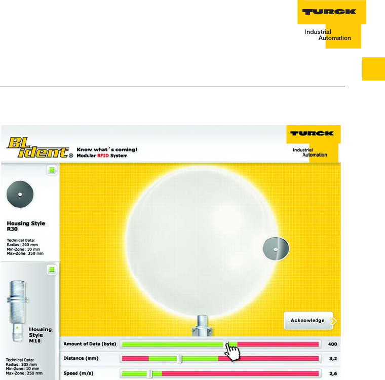
The BL ident configurator
The use of sensors and actuators – and even fieldbusses – is state-
of-the-art in many industrial fields. When RFID systems are used on
the other hand, there are always questions relating to the air-
interface, e.g. "How fast and at which distance can I move the data
carrier past the write-read heads?". That is to say that there is a
certain amount of general uncertainty concerning the range of
applications of an RFID system.
General details such as "recommended write-read distance" or
"transmission speed = 0.5 ms/ byte" are usually not sufficient for
evaluation of the usage of the devices in a determined application,
as the application variables such as data quantity, speed and
distance are the result of a complex interaction between the read-
write heads and data carriers.
With the “BL ident configurator” the respective application can be
simulated and the correct preliminary selection can be made.
The setting of applications parameters by "playing" with the values
allows the user to easily test the options and limits associated with
the respective combinations.
D101583 0207 BL ident 1 – 9
The TURCK BL ident System
1
The online variants of the configurator (available free on the Internet
at www.turck.com) accesses the data in the TURCK product
database and always provides the most up-to-date information.. In
addition to simulating the application, the configurator also
generates the corresponding data sheets and documentation.
Figure: 2
BL ident
configurator

The TURCK BL ident System
D101583 0207 BL ident1 – 10

2 – 1
BL ident System – Planning
D101583 0207 BL ident
2
2 TURCK-BL ident System – Planning
Selection criteria for data carriers, read-write head and interface module.......2
Transfer zone and read-write distance.............................................................3
Length of the transfer zone and width offset....................................................4
Minimum distance of the data carriers to read-write head,
influence of adjacent
fields..................................................................................................................4
Permissible direction of movement and alignment of the data carrier.............4
Reading and writing in static operation ............................................................4
Reading and writing in dynamic operation (on the fly)......................................5
Dwell time of the data carrier Td.......................................................................5
Calculation of the maximum quantity of user data in dynamic operation ........5
Minimum distances between two adjacent data carriers.................................6
BL ident System – Planning
2 – 2 D101583 0207 BL ident
Selection criteria for data carriers, read-write head and interface module
The application should be judged using the following criteria in order
to make the correct selection of BL ident system components:
Mechanical dimensions
Distance from data carriers to read-write heads when reading
and writing
Tolerances in the mechanical guidance
Static and/or dynamic transfer of data
Data quantities to be transferred
Speed with dynamic writing and reading (on the fly)
Metal-free areas with data carriers and read-write heads
Ambient conditions such as humidity, temperature, chemical
influences, etc.
There are special selection criteria relating to read-write heads:
Mechanical dimensions
Required transfer zone
Size of the data carrier in use
The following criteria should be considered specially for the use of
the interface modules:
Degree of protection
Bus type
Number of channels
2 – 3
BL ident System – Planning
D101583 0207 BL ident
2
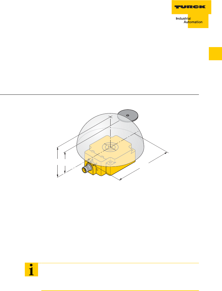
Transfer zone and read-write distance
The read-write head generates an alternating inductive field. The
recommended read-write distance results from the combination of
data carrier and read-write head. The appearance of the distribution
of this field depends on the design of the antenna in the data carrier
and in the read-write head.
Exchange of data is only possible within the transfer zone (Fig. 1)
with the parameters Lsr = length of the transfer zone and Sr =
recommended write-read distance. The transfer zone reduces when
the distance from the data carrier to the read-write head increases
and is reduced to a point at the threshold distance H, i.e. as the
distance increases less data can be transferred or the speed at
which the read-write head moves past the data carrier must be
reduced.
Figure 1
Transfer zone
Note
Using the BL ident configurator at www.turck.com allows the
relationships to be simulated.
Sr
HLsr

BL ident System – Planning
2 – 4 D101583 0207 BL ident
Length of the transfer zone LSr and width offset
The length of the transfer zone LSr (Fig. 1) is dependent on the
combination of data carrier and read-write head.
The width is particularly important for the tolerance of mechanical
tracking.
Minimum distance of the data carriers to read-write head, influence of adjacent fields
Adjacent fields are practically always available. Normally the
adjacent fields should not be used for transfer of data, so there must
be an minimum distance between data carriers and read-write head.
But with the TURCK BL ident system a minimum distance must not
be observed.
Permissible direction of movement and alignment of the data carrier
The data carrier can pass over the read-write head from any
direction.
The data carriers can have any horizontal alignment. They should
only be aligned in parallel to the read-write head.
Reading and writing in static operation
In static operation a data exchange is possible up to the range of the
threshold distance H. The data carrier must be positioned exactly
above the read-write head.
Reading and writing in dynamic operation (on the fly)
In dynamic operation the data carriers move past the read-write
head. A data exchange is only possible within the transfer zone.
Note
An illustrative representation of this relationship can be found in the
BL ident configurator at www.turck.com.

2 – 5
BL ident System – Planning
D101583 0207 BL ident
2
Dwell time of the data carrier Td
The dwell time Td is the time in which the data carrier is present in
the transfer zone of the read-write head as it passes by. The read-
write head exchanges data with the data carrier during this time.
The dwell time Td is calculated as follows:
Td = LSr / VTag
where:
LSr:length of the transfer zone
VTag:speed of the data carrier in dynamic operation
In static mode the dwell time can be as long as necessary. The dwell
time must be long enough to ensure that communication with the
data carrier has been completed.
In dynamic operation the dwell time is defined by the system
environment. The dwell time must be matched to the data quantity
to be transferred. Conversely, this means that the shorter the dwell
time, the lower the quantity of data to be transferred.
Calculation of the maximum quantity of user data in dynamic operation
The calculation of the maximum user data quantity is dependent on
the read-write head used and the corresponding data carrier.
Example:
Read-write head: TB-M18-H1147,
Data carrier: TW-R30-K2
Pass speed: 0.5 m/s
Note
At www.turck.com various examples relating to this topic can be
examined with the BL ident configurator.

BL ident System – Planning
2 – 6 D101583 0207 BL ident
The read-write head contacts the data carrier when it is entering
the transfer zone: This takes about 2.7 ms.
With the second contact to the data carrier the read-write head
recognizes the data carrier. A signal is sent to the interface
module: Duration about 12 ms.
The interface module sends a read-write command, e.g. read 4
bytes, incl. version and feedback of the data on the interface
module: Duration about 7 ms.
This results in total to about 22 ms.
Until 4 bytes of data have been processed by the interface module
takes about 5 ms/byte.
This means when the data carrier passes the read-write head, a
max. of 8 bytes can be read or written.
Minimum distances between two adjacent data carriers
The minimum distance between two data carriers is dependent on
the size of the data carrier and the read-write head.
In dynamic operation (on the fly) the minimum distance is still
dependent on the data quantity and the bus cycle time.
Note
With the BL ident configurator at www.turck.com different operating
states in dynamic operation can be simulated and represented.
Note
Corresponding tests for determination of the minimum distance
should be undertaken before commissioning.

3 – 1
Installation guidelines
D101583 0207 BL ident
3
3 Installation guidelines
Overview ...........................................................................................................2
Reduction of metallic influences.......................................................................2
Installation of several read-write heads on metal frames
or metal supports..............................................................................................3
No mounting of the data carrier directly on metal ............................................6
Conclusion – influence on the transfer from metal ...........................................7
Installation guidelines
3 – 2 D101583 0207 BL ident
Overview
Because of the inductive operating principle of the data carriers and
read-write heads, every type of metal (particularly iron and
ferromagnetic materials) should be avoided in proximity of these
devices, as they will influence the manner in which they function.
It is necessary to observe the following important points during
engineering and installation:
Minimum distance between read-write heads
Minimum distance between two adjacent data carriers (see
chapter 2, page 2 - 6)
Metal-free areas with installation of read-write heads and data
carriers on metals
Installation of several read-write heads on metal frames or
metal supports.
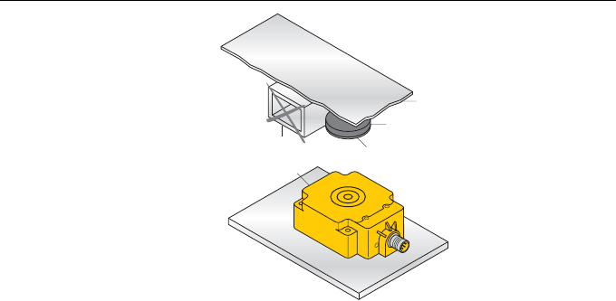
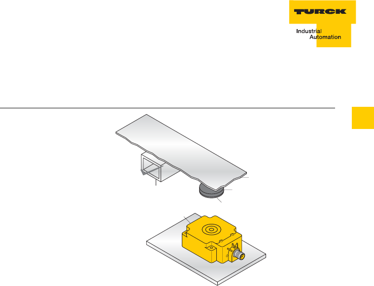
Reduction of metallic influences
Problem: A metal support is located above the transfer zone of the
read-write head. This influences the entire field. Specifically, the
transfer zone between read-write head and data carrier is reduced
(Fig. 1).
Figure 1
Interfering metal
supports.
metal core data carrier
read/write head
non-metallic spacer
plate
3 – 3
Installation guidelines
D101583 0207 BL ident
3
Remedy: Install the data carriers in a different manner and there will
no longer by an influence on the transfer zone (Fig. 2).
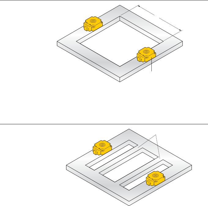
Installation of several read-write heads on metal frames or metal supports
Every read-write head which is mounted on metal couples a part of
the field to the metal support. If the minimum distance d and the
metal-free zones are observed, there is generally no mutual
influence. If however a metal frame should have an unfavourable
form an influence is still possible. This results in longer data transfer
times and error messages in the interface module.
Problem: Mutual interference of the read-write heads
Figure 2
Other
arrangement of
the data carrier
metal core
data carrier
read/write head
plate
non-metallic spacer
Installation guidelines
3 – 4 D101583 0207 BL ident
Remedy 1: Extend the distance d between both read-write heads
(Fig. 3).
Remedy 2: Fit one or several iron struts which should short-circuit
the parasitic fields (Fig. 4).
Figure 3
Extending the
distance
Figure 4
Fitting iron struts
d
read/write head
additional strunck
3 – 5
Installation guidelines
D101583 0207 BL ident
3
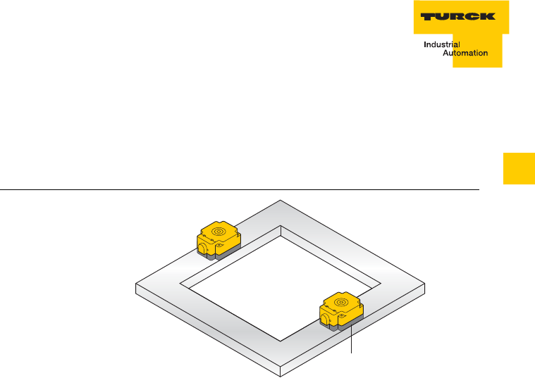
Remedy 3: Place a non-metallic intermediary element of 20 to 40
mm thickness between the read-write head and the iron frame. This
will significantly reduce the parasitic coupling of the field and the
support (Fig. 5).
Remedy 4: It is also possible to contact the read-write heads via the
function block (PLC) and to use it to switch them on and off. The
influence through another read-write head can be avoided using the
selective mode, where the channel in whose transfer window the
data is located is active (see manual BL ident Proxy-Ident-Block
(PIB), D101578). Using this method the adjacent read-write heads
do not emit a field and there is no mutual interference.
Figure 5
Addition of an
intermediary non-
metallic element
non-metallic spacer
Installation guidelines
3 – 6 D101583 0207 BL ident
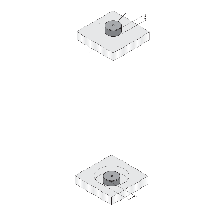
No mounting of the data carrier directly on metal
The data carriers (with the exception of high temperature data
carriers) may not be mounted directly on metal. Non-metallic
spacers (see chapter 9, Accessories) enable mounting which does
not lead to an interruption of the functions (Fig. 6).
The data carriers may not be mounted so that the necessary
minimum distance to metal and to the data carriers around them is
less than the minimum distance. The minimum distance is
dependent on the housing design of the read-write head; a = 10 mm
around the data carrier can be assumed (Fig. 7). The high
temperature data carrier (see page 5 - 2, table 1) can be constructed
so that it can be mounted directly on metal without the need for
additional measures.
Figure 6
Installation with
spacers
Figure 7
Installation
considering the
minimum distance
from metal
h
metal
non-metallic spacer data carrier
a

3 – 7
Installation guidelines
D101583 0207 BL ident
3
Conclusion – influence on the transfer from metal
The following points should be considered with the installation of the
BL ident components:
Data carriers (except high temperature data carriers) can not be
mounted directly on metal or suitable accessories must be used
(spacers)
It is important to ensure that no metallic rails (or similar parts)
intersect the transfer zone. The metal rails would interfere with
the field data.
Only plastic or stainless steel screws can be used for attachment
of the read-write heads.

Installation guidelines
3 – 8 D101583 0207 BL ident

4 – 1
EMC Directives
D101583 0207 BL ident
4
4 EMC directives
For whom are the EMC directives intended?................................................... 2
Dispersion of electromagnetic interference ......................................................2
How can RFID be subject to interference? .................................................3
Coupled interference...................................................................................3
What does EMC mean? ....................................................................................4
Fundamentals for EMC protection....................................................................5
Installation in a switch cabinet ....................................................................6
Avoiding sources of interference.................................................................7
Potential equalization ..................................................................................7
Shielding the cable......................................................................................7

EMC Directives
4 – 2 D101583 0207 BL ident
For whom are the EMC directives intended?
These EMC directives are intended for:
Project engineers and planners who are planning the system
with the RFID modules to be configured.
Installation personnel, service technicians and engineers, who
use this description to correctly lay the connection cables
or
have to remedy the existing problems during a malfunction.
In this chapter you will learn more about the EMC guidelines,
particularly:
Dispersion of electromagnetic interference
What does EMC mean?
Fundamentals for EMC protection
Installation in a switch cabinet
Avoiding sources of interference
Potential equalisation
Shielding the cable
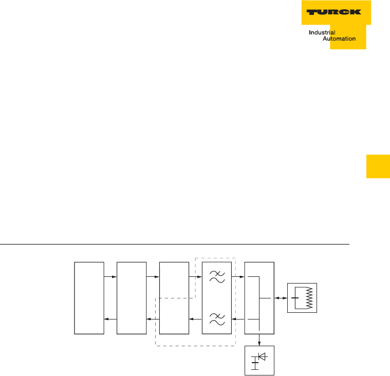
Dispersion of electromagnetic interference
In a system or installation electromagnetic interference can only occur
if the following components are mutually present:
Source of interference
Interference path
Susceptible equipment.
If one of these components is not present (for example the
interference path), no interference will occur even if the source of
interference sends high levels of interference (Fig. 1):
Figure 1
Interference
components
source of interference
e.g. motor
susceptible equipment
e.g. read/write head
link
e.g. cable connector

4 – 3
EMC Directives
D101583 0207 BL ident
4
The measures for prevention of the interference (EMC) are relevant
for all three components. The manufacturer is obliged to undertake
all possible measures to counter the development of sources of
interference.
The installation design must be implemented to ensure that mutual
interference of the individual components is avoided or kept to as
low a level as possible.
How can RFID be subject to interference?
Problem: interference radiation from the power supply when
switching mode power supplies are used.
Remedy: use of a stabilized power supply
Problem: interference via the serial connection cable.
Remedy: improved cable shielding and/or read-write head
earthing
HF interference via the antenna from another read-write head or
via an external source of interference which operates using the
same frequency.
Remedy: the interference from another read-write head can be
avoided by using the selective mode (see manual
BL ident Proxy-Ident-Block (PIB), D101578).
Coupled interference
There are four possibilities for coupled interference:
Galvanic coupled interference
Capacitive coupled interference
Inductive coupled interference
Radiated interference
There are different causes for the radiated interference on the data
interface paths:
With cables and wiring:
Incorrect or poorly laid
Missing or incorrectly connected shield
Unfavourable arrangement of the cable
EMC Directives
4 – 4 D101583 0207 BL ident
With the switch cabinet or housing:
Missing or incorrectly wired potential equalization wiring
Missing or incorrect earthing
Unfavourable arrangement
Modules which are not mounted in a fixed position
Unfavourable switch cabinet design.
What does EMC mean?
The increasing component density, increased switching speed of
power electronics and the continuous rise in switching speeds
present more and more sources of interference to electronic
elements of a system. The following generally applies: the higher the
level of automation, the higher the danger of mutual interference.
Definition of EMC:
“Electromagnetic compatibility (EMC) is the capability of an
electrical or electronic device in an electromagnetic environment to
function without fault, without influencing or interfering with the
environment beyond defined limits.”
The TURCK BL ident devices are subjected to test compliance to
the following standards:
EN 61000-4-2 (ESD)
EN 61000-4-3 (Electromagnetic fields)
EN 61000-4-4 (Burst)
EN 61000-4-5 (Surge)
EN 61000-4-6 (immunity to conducted disturbances induced by
radio-frequency fields)
As the RFID modules are only components of an overall system and
sources of interferences can result from the combination of different
components, the design of a system or installation must be subject
to certain guidelines.
In order to obtain an installation which is immune to interference, a
whole package of measures must be implemented; where the
operator of the system or installation is responsible for the RFI
suppression. They must observe and comply with the local and
national stipulations and directives. All measures, which have been

4 – 5
EMC Directives
D101583 0207 BL ident
4
undertaken during system design save expensive modifications and
elimination of interference at a later date.
Fundamentals for EMC protection
The following elementary rules relating to electromagnetic
compatibility (EMC) must be observed:
Shielding by a housing
Protect the device from external sources of interference by the
installation in a switch cabinet or housing. The cabinet or the
housing must be included in the connection to earth.
Shield the electromagnetic fields from inductances by partition
panels of devices. Use shielded data transmission cables with
metallic connector housings.
Large area ground connections
Connect all inductive metal parts over a large area and use a low
resistance for radio frequencies. Establish a large area
connection between the inactive metal parts and the central
earthing point.
Integrate the shield earth into the earthing concept, i.e. the end
of the shield must be connected to a large area to earth.
Planning of the cable routes
Divide the cables into power groups and lay them separately.
Lay the high power cables and the data cables in separate ducts
or bundles.
Introduce the entire cabling into the cabinet only from one side
and on a single level when possible.
Lay the data cables as close to earthed surfaces as possible.
Twist the incoming and outgoing cables of individually laid
conductor pairs.
In many cases an independent cable guidance for the bus cable
is already provided. Ideally this should also be used for laying the
data cables between read-write heads and interface modules.
Shielding of cables
Shield the data transfer cables and apply the shield on gateway
side. Shield the analogue cables and apply the shield at one end,
e.g. on the drive unit.
Always apply the cable shields at the entry to the switch cabinet
to a large area on the grounding bar and attach them with fixing
clamps.
EMC Directives
4 – 6 D101583 0207 BL ident
Connect the applied shield to the module without interruption.
Use a braided shield and not a metal foil shield.
Mains and signal filter
Use the mains filter with metal housing.
Connect the filter housing on a wide area and with a low radio
frequency resistance to the switch cabinet earth.
Never attach the filter housing to painted surfaces.
Attach the filter at the switch cabinet entry or in the direction of
the interference source.
Installation in a switch cabinet
Metal housings shield susceptible equipment against magnetic and
electrical fields as well as electromagnetic waves. The better that
the induced interference current can flow, the better that the
interference field will weaken itself. It is therefore essential to ensure
that all housing panels are connected electrically conducting to
each other.
If the switch cabinet panels are insulated from one another, an RF
conductive connection using metal braiding and RF clips or RF
paste (the greater the surface area of the connection the better)
must be possible.
Interference can be avoided by optimum switch cabinet design. The
following generally applies:
The effects of the interference generally reduce as the distance
between the susceptible equipment and the source of
interference increases.
An additional reduction in interference can be achieved by
installation of shield panels
Signal cables should keep a minimum distance of at least 10 cm
from high power cables.
External interference induced through the mains is avoided by the
installation of mains filters. Ensure that the mains filter is correctly
rated and fitted directly at the entry to the switch cabinet.

4 – 7
EMC Directives
D101583 0207 BL ident
4
Avoiding sources of interference
Avoid the installation of sources of interference which occur
primarily due to switched inductances.
Interference is generated primarily by relays, contactors, fluorescent
lamps in the switch cabinet and valves, and can be avoided by the
use of RC combinations, freewheel diodes etc. This also avoids
inductive interference in the cables which are laid parallel to the coil
cables.
Potential equalisation
If the system sections are subject to a different design and different
voltage levels result, potential differences can result between the
different sections of the system. Equalization currents then flow via
signal cables (potential equalization should not be confused with a
protective earth).
Therefore correctly implemented potential equalization is essential.
The following points should be observed:
The potential equalization cable must have a sufficient cross-
section (min. 10 mm2).
The distance between signal cables and the respective potential
equalization cable must be as small as possible.
A stranded conductor must be used.
If the potential equalization cables are connected to the central
potential equalization bars, the power components and the non-
power components must be combined.
Shielding the cable
Signal cables must be shielded in order to avoid coupled
interference. Even though the best shielding effect when laying the
cables is achieved by using steel ducts, the use of cables with
braided shields is usually sufficient. Decisive for the effect of the
shield in both cases is however the correct connection, as a non-
connected or incorrectly connected shield has no effect.
EMC Directives
4 – 8 D101583 0207 BL ident
The following must be observed:
As the interference signals are frequently in a range > 10 kHz, a
large area shield connection is necessary.
The shield bar is very conductive and connected over a large
area with the switch cabinet housing and must be as near as
possible to the cable entry. The cable must be stripped and
connected to the grounding bar with an RF clip or cable tie.
The shielding bar must be connected with the PE bar.
If shielded cables have to be interrupted, the shield must
continue via the corresponding connector housing using
suitable connectors.
If intermediate connectors are used which do not feature a
suitable shield, the shield must be connected via cable clips to
the point where it is interrupted.

5 – 1
Description of the data carrier
D101583 0207 BL ident
5
5 Description of the data carrier
Type overview...................................................................................................2
Function principle..............................................................................................3
Memory module ..........................................................................................3
Data carrier electronics ...............................................................................4
Data carrier antenna....................................................................................4
Technical data
TW-R16-B64 ...............................................................................................5
TW-R16-B128 .............................................................................................7
TW-R20-B128 .............................................................................................9
TW-R30-B128 ...........................................................................................11
TW-R50-B128 ...........................................................................................13
TW-R20-K2................................................................................................15
TW-R30-K2................................................................................................17
TW-R50-K2................................................................................................19
TW-R22-HT-B64 .......................................................................................21
TW-R50-90-HT-B128................................................................................23
TW-R50-90-HT-K2....................................................................................25
TW-I14-B128.............................................................................................27
TW-L43-43-F-B128...................................................................................29
TW-L82-49-P-B128...................................................................................31

Description of the data carrier
5 – 2 D101583 0207 BL ident
Type overview
Table 1:
Data carrier type
overview
Type Memory
size Memory
type Highly
t
emperature
resistant
TW-R16-B64 64 Byte EEPROM –
TW-R16-B128 128 Byte EEPROM –
TW-R20-B128 128 Byte EEPROM –
TW-R30-B128 128 Byte EEPROM –
TW-R50-B128 128 Byte EEPROM –
TW-R20-K2 2 kByte FRAM –
TW-R30-K2 2 kByte FRAM –
TW-R50-K2 2 kByte FRAM –
TW-R22-HT-B64 64 Byte EEPROM ✔
TW-R50-90-HT-B128 128 Byte EEPROM ✔
TW-R50-90-HT-K2 2 kByte FRAM ✔
TW-I14-B128 128 Byte EEPROM –
TW-L43-43-F-B128 128 Byte EEPROM –
TW-L82-49-P-B128 128 Byte EEPROM –
5 – 3
Description of the data carrier
D101583 0207 BL ident
5
Function principle
The BLident data carriers (TAGs) can be written and read on a non-
contact basis using the corresponding read-write heads. The
operating frequency is 13.56 MHz.
The data carriers are passive, i.e. without batteries. If the data
carriers enter the transfer range of a read-write head, the energy is
inductively coupled and the data transfer is initiated.
The achievable distances vary depending on the sizes from
15…200 mm. All housing styles (with the exception of the
TW-R16...-B128, EEPROM only) are available both as EEPROM
and FRAM memory variants. The BLident data carrier consists of
a memory module, electronics and an antenna (see Fig. 1).
Memory module
The information on the data carrier can be read – and new data can
also be added (read/write). The memory size is 64 Bytes, 128 Bytes
or 2 KBytes.
The memory consists alternatively of the following components:
EEPROM: unlimited read but limited write cycles are possible
(105). No battery required.
FRAM = ferroelectric memory: unlimited read and almost
unlimited write cycles are possible (1010). No battery required.
Figure 1
Block diagram
Data carrier
UB
modulator
demodulator
control logicsmemory
read/write
Description of the data carrier
5 – 4 D101583 0207 BL ident
The data retention time of the memory is:
1 year at 85 °C,
10 years at 55 °C,
120 years at 25 °C.
Electrical fields do not have an influence as they are normally have
a frequency which is much too low to erase the memory.
Data carrier electronics
The electronics ensure the communication on the data carrier side
with the read-write head.
Data carrier antenna
The antenna is designed as an air coil and is used to transfer data
and energy between the data carrier and the read-write head.

5 – 5
Description of the data carrier
D101583 0207 BL ident
5
Technical data TW-R16-B64
Figure 2
TW-R16-B64
Table 2:
TW-R16-B64 Type
Ident-No. TW-R16-B64
6900???
Memory data
Operating frequency 13.56 MHz
Memory size 128 Bytes
Number of read operations unlimited
Number of write operations 105
Read time (typical) 0.5…5 ms/Byte
Write time (typical) 3…6 ms/Byte
Memory type EEPROM
Installation guidelines
Minimum distances when
mounting in metal (around the
data carrier)
10 mm
General data
Colour black
Ambient temperature -25…+85 °C
2,5
16
3

Description of the data carrier
5 – 6 D101583 0207 BL ident
Storage temperature -25…+120 °C
+160 °C (1 x 35 h)
+220 °C (1 x 30 s)
Degree of protection (IEC
60529/EN 60529) IP68
Housing material Epoxy, plastic-moulded
Table 2:
TW-R16-B64 Type
Ident-No. TW-R16-B64
6900???

5 – 7
Description of the data carrier
D101583 0207 BL ident
5
Technical data TW-R16-B128
Figure 3
TW-R16-B128
Table 3:
TW-R16-B128 Type
Ident-No. TW-R16-B128
6900501
Memory data
Operating frequency 13.56 MHz
Memory size 128 Bytes
Number of read operations unlimited
Number of write operations 105
Read time (typical) 0.5…5 ms/Byte
Write time (typical) 3…6 ms/Byte
Memory type EEPROM
Installation guidelines
Minimum distances when
mounting in metal (around the
data carrier)
10 mm
General data
Colour black
Ambient temperature -25…+85 °C
2,5
16
3

Description of the data carrier
5 – 8 D101583 0207 BL ident
Storage temperature -25…+120 °C
+160 °C (1 x 35 h)
+220 °C (1 x 30 s)
Degree of protection (IEC
60529/EN 60529) IP68
Housing material Epoxy, plastic-moulded
Table 3:
TW-R16-B128 Type
Ident-No. TW-R16-B128
6900501

5 – 9
Description of the data carrier
D101583 0207 BL ident
5
Technical data TW-R20-B128
Figure 4
TW-R20-B128
Table 4:
TW-R20-B128 Type
Ident-No. TW-R20-B128
6900502
Memory data
Operating frequency 13.56 MHz
Memory size 128 Bytes
Number of read operations unlimited
Number of write operations 105
Read time (typical) 0.5…5 ms/Byte
Write time (typical) 3…6 ms/Byte
Memory type EEPROM
Installation guidelines
Minimum distances when
mounting in metal (around the
data carrier)
10 mm
General data
Colour black
Ambient temperature -25…+85 °C
1,5
ø 20
2,5
ø 20

Description of the data carrier
5 – 10 D101583 0207 BL ident
Storage temperature -40…+90 °C
+140 °C (1 x 100 h)
Degree of protection (IEC
60529/EN 60529) IP68
Housing material PA6
Table 4:
TW-R20-B128 Type
Ident-No. TW-R20-B128
6900502

5 – 11
Description of the data carrier
D101583 0207 BL ident
5
Technical data TW-R30-B128
Figure 5
TW-R30-B128
Table 5:
TW-R30-B128 Type
Ident-No. TW-R30-B128
6900503
Memory data
Operating frequency 13.56 MHz
Memory size 128 Bytes
Number of read operations unlimited
Number of write operations 105
Read time (typical) 0.5…5 ms/Byte
Write time (typical) 3…6 ms/Byte
Memory type EEPROM
Installation guidelines
Minimum distances when
mounting in metal (around the
data carrier)
10 mm
General data
Colour black
Ambient temperature -25…+85 °C
1,5
ø 30
ø 3,2
2,5
ø 30
ø 5,2

Description of the data carrier
5 – 12 D101583 0207 BL ident
Storage temperature -40…+90 °C
+140 °C (1 x 100 h)
Degree of protection (IEC
60529/EN 60529) IP68
Housing material PA6
Table 5:
TW-R30-B128 Type
Ident-No. TW-R30-B128
6900503

5 – 13
Description of the data carrier
D101583 0207 BL ident
5
Technical data TW-R50-B128
Figure 6
TW-R50-B128
Table 6:
TW-R50-B128 Type
Ident-No. TW-R50-B128
6900504
Memory data
Operating frequency 13.56 MHz
Memory size 128 Bytes
Number of read operations unlimited
Number of write operations 105
Read time (typical) 0.5…5 ms/Byte
Write time (typical) 3…6 ms/Byte
Memory type EEPROM
Installation guidelines
Minimum distances when
mounting in metal (around the
data carrier)
10 mm
General data
Colour black
Ambient temperature -25…+85 °C
1,5
ø 50
ø 4,2
3
ø 50
ø 5,2

Description of the data carrier
5 – 14 D101583 0207 BL ident
Storage temperature -40…+90 °C
+140 °C (1 x 100 h)
Degree of protection (IEC
60529/EN 60529) IP68
Housing material PA6
Table 6:
TW-R50-B128 Type
Ident-No. TW-R50-B128
6900504

5 – 15
Description of the data carrier
D101583 0207 BL ident
5
Technical data TW-R20-K2
Figure 7
TW-R20-K2
Table 7:
TW-R20-K2 Type
Ident-No. TW-R20-K2
6900505
Memory data
Operating frequency 13.56 MHz
Memory size 2 KBytes
Number of read operations unlimited
Number of write operations 1010
Read time (typical) 0.5…5 ms/Byte
Write time (typical) 0.5…5 ms/Byte
Memory type FRAM
Installation guidelines
Minimum distances when
mounting in metal (around the
data carrier)
10 mm
General data
Colour black
Ambient temperature -20…+85 °C
2,5
ø 20

Description of the data carrier
5 – 16 D101583 0207 BL ident
Storage temperature -20…+85 °C
+140 °C (1 x 100 h)
Degree of protection (IEC
60529/EN 60529) IP68
Housing material PA6
Table 7:
TW-R20-K2 Type
Ident-No. TW-R20-K2
6900505

5 – 17
Description of the data carrier
D101583 0207 BL ident
5
Technical data TW-R30-K2
Figure 8
TW-R30-K2
Table 8:
TW-R30-K2 Type
Ident-No. TW-R30-K2
6900506
Memory data
Operating frequency 13.56 MHz
Memory size 2 KBytes
Number of read operations unlimited
Number of write operations 1010
Read time (typical) 0.5…5 ms/Byte
Write time (typical) 0.5…5 ms/Byte
Memory type FRAM
Installation guidelines
Minimum distances when
mounting in metal (around the
data carrier)
10 mm
General data
Colour black
Ambient temperature -20…+85 °C
2,5
ø 30
ø 5,2

Description of the data carrier
5 – 18 D101583 0207 BL ident
Storage temperature -20…+85 °C
+140 °C (1 x 100 h)
Degree of protection (IEC
60529/EN 60529) IP68
Housing material PA6
Table 8:
TW-R30-K2 Type
Ident-No. TW-R30-K2
6900506
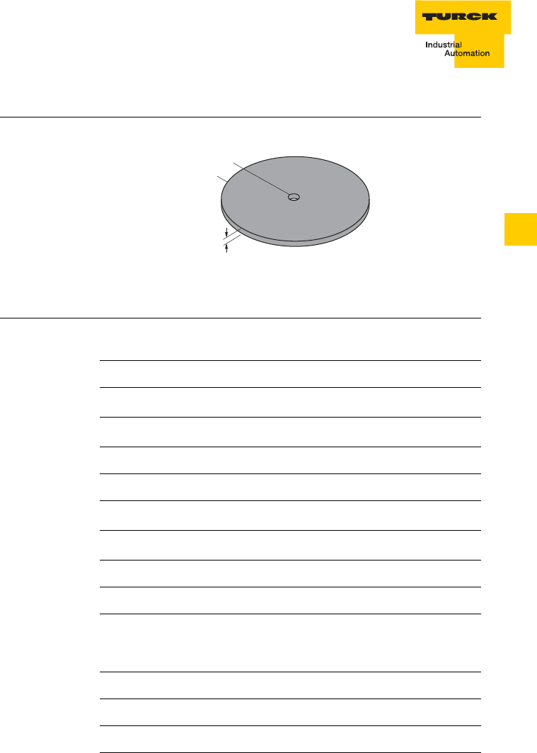
5 – 19
Description of the data carrier
D101583 0207 BL ident
5
Technical data TW-R50-K2
Figure 9
TW-R50-K2
Table 9:
TW-R50-K2 Type
Ident-No. TW-R50-K2
6900507
Memory data
Operating frequency 13.56 MHz
Memory size 2 KBytes
Number of read operations unlimited
Number of write operations 1010
Read time (typical) 0.5…5 ms/Byte
Write time (typical) 0.5…5 ms/Byte
Memory type FRAM
Installation guidelines
Minimum distances when
mounting in metal (around the
data carrier)
10 mm
General data
Colour black
Ambient temperature -20…+85 °C
3
ø 50
ø 5,2

Description of the data carrier
5 – 20 D101583 0207 BL ident
Storage temperature -20…+85 °C
+140 °C (1 x 100 h)
Degree of protection (IEC
60529/EN 60529) IP68
Housing material PA6
Table 9:
TW-R50-K2 Type
Ident-No. TW-R50-K2
6900507
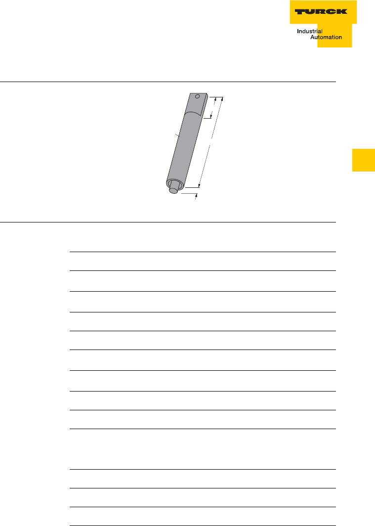
5 – 21
Description of the data carrier
D101583 0207 BL ident
5
Technical data TW-R22-HT-B64
Figure 10
TW-R22-HT-B64
Table 10:
TW-R22-HT-B64 Type
Ident-No. TW-R22-HT-B64
1542323
Memory data
Operating frequency 13.56 MHz
Memory size 64 Bytes
Number of read operations unlimited
Number of write operations 105
Read time (typical) 0.5…5 ms/Byte
Write time (typical) 3…6 ms/Byte
Memory type EEPROM
Installation guidelines
Minimum distances when
mounting in metal (around the
data carrier)
10 mm
General data
Colour black
Ambient temperature -25…+85 °C (time-dependent)
30
125
10
ø 22

Description of the data carrier
5 – 22 D101583 0207 BL ident
Storage temperature -40…+210 °C
Degree of protection (IEC
60529/EN 60529) IP68
Housing material PA66
Table 10:
TW-R22-HT-B64 Type
Ident-No. TW-R22-HT-B64
1542323
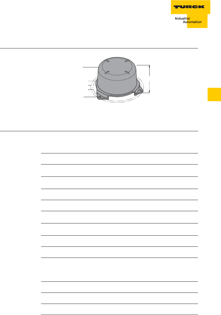
5 – 23
Description of the data carrier
D101583 0207 BL ident
5
Technical data TW-R50-90-HT-B128
Figure 11
TW-R50-90-HT-
B128
Table 11:
TW-R50-90HT-
B128
Type
Ident-No. TW-R50-90-HT-B128
1542326
Memory data
Operating frequency 13.56 MHz
Memory size 128 Bytes
Number of read operations unlimited
Number of write operations 105
Read time (typical) 0.5…5 ms/Byte
Write time (typical) 3…6 ms/Byte
Memory type EEPROM
Installation guidelines
Minimum distances when
mounting in metal (around the
data carrier)
–
General data
Colour black
Ambient temperature -25…+85 °C (time-dependent)
ø 95
ø 108,5
ø 136,5
ø 125
68
ø 5,5
(3 x 120°)

Description of the data carrier
5 – 24 D101583 0207 BL ident
Storage temperature -40…+210 °C
Degree of protection (IEC
60529/EN 60529) IP67
Housing material PA66
Table 11:
TW-R50-90HT-
B128
Type
Ident-No. TW-R50-90-HT-B128
1542326

5 – 25
Description of the data carrier
D101583 0207 BL ident
5
Technical data TW-R50-90-HT-K2
Figure 12
TW-R50-90-HT-
K2
Table 12:
TW-R50-90-HT-
K2
Type
Ident-No. TW-R50-90-HT-K2
1542329
Memory data
Operating frequency 13.56 MHz
Memory size 2 KBytes
Number of read operations unlimited
Number of write operations 1010
Read time (typical) 0.5…5 ms/Byte
Write time (typical) 0.5…5 ms/Byte
Memory type FRAM
Installation guidelines
Minimum distances when
mounting in metal (around the
data carrier)
–
General data
Colour black
Ambient temperature -20…+85 °C (time-dependent)
ø 95
ø 108,5
ø 136,5
ø 125
68
ø 5,5
(3 x 120°)

Description of the data carrier
5 – 26 D101583 0207 BL ident
Storage temperature -40…+210 °C
Degree of protection (IEC
60529/EN 60529) IP68
Housing material PA66
Table 12:
TW-R50-90-HT-
K2
Type
Ident-No. TW-R50-90-HT-K2
1542329

5 – 27
Description of the data carrier
D101583 0207 BL ident
5
Technical data TW-I14-B128
Figure 13
TW-I14-B128
Table 13:
TW-I14-B128 Type
Ident-No. TW-I14-B128
6900526
Memory data
Operating frequency 13.56 MHz
Memory size 128 Bytes
Number of read operations unlimited
Number of write operations 105
Read time (typical) 0.5…5 ms/Byte
Write time (typical) 3…6 ms/Byte
Memory type EEPROM
Installation guidelines
Minimum distances when
mounting in metal (around the
data carrier)
10 mm
General data
Colour black
Ambient temperature -25…+85 °C
14

Description of the data carrier
5 – 28 D101583 0207 BL ident
Storage temperature -25…+120 °C
+160 °C (1 x 35 h)
+220 °C ( 1 x 30 s)
Degree of protection (IEC
60529/EN 60529) IP10
Housing material Epoxy foil
Table 13:
TW-I14-B128 Type
Ident-No. TW-I14-B128
6900526

5 – 29
Description of the data carrier
D101583 0207 BL ident
5
Technical data TW-L43-43-F-B128
Figure 14
TW-L43-43-F-
B128
Table 14:
TW-L43-43-F-
B128
Type
Ident-No. TW-L43-43-F-B128
6901344
Memory data
Operating frequency 13.56 MHz
Memory size 128 Bytes
Number of read operations unlimited
Number of write operations 105
Read time (typical) 0.5…5 ms/Byte
Write time (typical) 3…6 ms/Byte
Memory type EEPROM
Installation guidelines
Minimum distances when
mounting in metal (around the
data carrier)
10 mm
General data
Colour white
Ambient temperature -20…+70 °C
43
43

Description of the data carrier
5 – 30 D101583 0207 BL ident
Storage temperature -20…+70 °C
Degree of protection (IEC
60529/EN 60529) IP40
Housing material Foil, self-adhesive
Table 14:
TW-L43-43-F-
B128
Type
Ident-No. TW-L43-43-F-B128
6901344

5 – 31
Description of the data carrier
D101583 0207 BL ident
5
Technical data TW-L82-49-P-B128
Figure 15
TW-L82-49-P-
B128
Table 15:
TW-L82-49-P-
B128
Type
Ident-No. TW-L82-49-P-B128
6901345
Memory data
Operating frequency 13.56 MHz
Memory size 128 Bytes
Number of read operations unlimited
Number of write operations 105
Read time (typical) 0.5…5 ms/Byte
Write time (typical) 3…6 ms/Byte
Memory type EEPROM
Installation guidelines
Minimum distances when
mounting in metal (around the
data carrier)
10 mm
General data
Colour white
Ambient temperature -20…+70 °C
49
82

Description of the data carrier
5 – 32 D101583 0207 BL ident
Storage temperature -20…+70 °C
Degree of protection (IEC
60529/EN 60529) IP40
Housing material Paper, self-adhesive
Table 15:
TW-L82-49-P-
B128
Type
Ident-No. TW-L82-49-P-B128
6901345

6 – 1
Description of the read-write heads
D101583 0207 BL ident
6
6 Description of the read-write heads
Type overview...................................................................................................2
Function principle..............................................................................................3
Read-write head electronics .......................................................................3
Read-write head antenna............................................................................4
Technical data of the read-write heads
TB-M18-H1147............................................................................................6
TB-M18-H1147/S1126 (optimised for special data carriers).......................7
TB-EM18WD-H1147 (wash-down)..............................................................8
TB-EM18WD-H1147/S1126 (wash-down, optimised for special data
carriers) .......................................................................................................9
TN-M18-H1147 .........................................................................................10
TN-M18-H1147/S1126 (optimised for special data carriers) ....................11
TN-EM18WD-H1147 (wash-down)............................................................12
TN-EM18WD-H1147/S1126 (wash-down, optimised for special data
carriers)......................................................................................................13
TB-M30-H1147..........................................................................................14
TB-M30-H1147/S1126 (optimised for special data carriers).....................15
TB-EM30WD-H1147 (wash-down)............................................................16
TB-EM30WD-H1147/S1126 (wash-down, optimised for special data
carriers)......................................................................................................17
TN-M30-H1147 .........................................................................................18
TN-M30-H1147/S1126 (optimised for special data carriers) ....................19
TN-EM30WD-H1147 (wash-down)............................................................20
TN-EM30WD-H1147/S1126 (wash-down, optimised for special data
carriers)......................................................................................................21
TN-CK40-H1147........................................................................................22
TN-CK40-H1147/S1126 (optimised for special data carriers)...................23
TN-Q80-H1147..........................................................................................24
TN-Q80-H1147/S1126 (optimised for special data carriers).....................25
TNER-Q80-H1147 (increased range).........................................................26
TNLR-Q80-H1147 (long range) .................................................................27
TNLR-Q80-H1147/S1126 (long range, optimised for special
data carriers)..............................................................................................28
TN-S32XL-H1147......................................................................................29
Connection of the read-write heads ...............................................................30

Description of the read-write heads
6 – 2 D101583 0207 BL ident
Type overview
Table 1:
Type overview
read-write
heads
Type Installa-
tion
c
onditions
Output
function Connec-
tion
TB-M18-H1147
TB-M18-H1147/S1126
TB-EM18WD-H1147
TB-EM18WD-H1147/S1126
flush Read/write via
BLident
cable
TN-M18-H1147
TN-M18-H1147/S1126
TN-EM30WD-H1147
TN-EM30WD-H1147/S1126
non-
flush Read/write via
BLident
cable
TB-M30-H1147
TB-M30-H1147/S1126
TB-EM30WD-H1147
TB-EM30WD-H1147/S1126
flush Read/write via
BLident
cable
TN-M30-H1147
TN-M30-H1147/S1126
TN-EM30WD-H1147
TN-EM30WD-H1147/S1126
non-
flush Read/write via
BLident
cable
TN-CK40-H1147
TN-CK40-H1147/S1126 non-
flush,
(flush
instal-
lation
possible)
Read/write via
BLident
cable
TN-Q80-H1147
TN-Q80-H1147/S1126
TNER-Q80-H1147
TNLR-Q80-H1147
TNLR-Q80-H1147/S1126
non-
flush,
(installatio
n on metal
possible)
Read/write via
BLident
cable
TN-S32XL-H1147 non-
flush
(
installation
on metal
possible)
Read/write via
BLident
cable
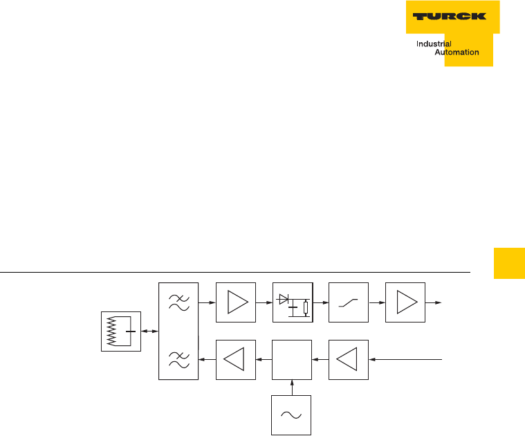
6 – 3
Description of the read-write heads
D101583 0207 BL ident
6
Function principle
The BLident read-write heads (transceivers) are used for non-
contact data exchange with the corresponding data carriers (TAGs).
They form the so-called air-interface (transfer window), whose size
varies depending on the combination of data carrier and transceiver.
In this air-interface the data carrier is supplied with energy and the
exchange of data is also implemented. The operating frequency is
13.56 MHz.
The achievable distances vary depending on the sizes from 15…200
mm. The read-write heads consist of electronics and an antenna.
(Figure 1)
Read-write head electronics
The electronics ensure the communication between the data carrier,
the read-write head and the BLident interface module.
Figure 1
Block diagram
Read-write head
Modulator
Demodulator
Generator

Description of the read-write heads
6 – 4 D101583 0207 BL ident
Read-write head antenna
The antenna consists of an air coil. It is used to transfer data and
energy between the data carrier and the read-write head. The
antenna generates an electromagnetic field which is detected by the
data carrier within the transfer zone. A data and energy transfer is
only possible as long as the data carrier is located in this field
(Figure 2).
Figure 2
Transfer zone
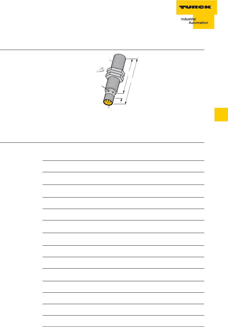
6 – 5
Description of the read-write heads
D101583 0207 BL ident
6
Technical data TB-M18-H1147
Figure 3
TB-M18-H1147
Table 2:
TB-M18-H1147 Type
Ident-No. TB-M18-H1147
7030001
Mounting condition flush
Ambient temperature -25…+ 70 °C
Data transfer inductive
Output function Read/write
Operating frequency 13.56 MHz
Housing style Threaded barrel, M18 × 1
Housing material Metal, CuZn, chrome-plated
Active face material Plastic, PA12-GF30
Connection Connector, M12 × 1
Vibration resistance 55 Hz (1 mm)
Shock resistance 30 g (11 ms)
Degree of protection IP67
Power ON indication Green LED
Function display Green LED, flashing
24/4
56
72
LED
M18 x 1
9
M12 x 1

Description of the read-write heads
6 – 6 D101583 0207 BL ident
Technical data TB-M18-H1147/S1126
Figure 4
TB-M18-H1147/
S1126
Table 3:TB-M18-
H1147/S1126 Type
Ident-No. TB-M18-H1147/S1126
7030212
Mounting condition flush
Ambient temperature -25…+ 70 °C
Data transfer inductive
Output function Read/write
Operating frequency 13.56 MHz
Housing style Threaded barrel, M18 × 1
Housing material Metal, CuZn, chrome-plated
Active face material Plastic, PA12-GF30
Connection Connector, M12 × 1
Vibration resistance 55 Hz (1 mm)
Shock resistance 30 g (11 ms)
Degree of protection IP67
Power ON indication Green LED
Function display Green LED, flashing
24/4
56
72
LED
M18 x 1
9
M12 x 1

6 – 7
Description of the read-write heads
D101583 0207 BL ident
6
Technical data TB-EM18WD-H1147
Figure 5
TB-EM18WD-
H1147
Table 4:TB-
EM18WD-H1147 Type
Ident-No. TB-EM18WD-H1147
7030224
Mounting condition flush
Ambient temperature -25…+ 70 °C
Data transfer inductive
Output function Read/write
Operating frequency 13.56 MHz
Housing style Threaded barrel, M18 × 1
Housing material Metal, A4 1.4404 (AISI 316L)
Active face material Plastic, LCP-GF30
Connection Connector, M12 × 1
Vibration resistance 55 Hz (1 mm)
Shock resistance 30 g (11 ms)
Degree of protection IP67
Power ON indication Green LED
Function display Green LED, flashing
24/4
56
72
LED
M18 x 1
9
M12 x 1

Description of the read-write heads
6 – 8 D101583 0207 BL ident
Technical data TB-EM18WD-H1147/S1126
Figure 6
TB-EM18WD-
H1147/S1126
Table 5:TB-EM18
WD-H1147/S1126
Type
Ident-No. TB-EM18WD-H1147/S1126
7030228
Mounting condition flush
Ambient temperature -25…+ 70 °C
Data transfer inductive
Output function Read/write
Operating frequency 13.56 MHz
Housing style Threaded barrel, M18 × 1
Housing material Metal, A4 1.4404 (AISI 316L)
Active face material Plastic, LCP-GF30
Connection Connector, M12 × 1
Vibration resistance 55 Hz (1 mm)
Shock resistance 30 g (11 ms)
Degree of protection IP67
Power ON indication Green LED
Function display Green LED, flashing
24/4
56
72
LED
M18 x 1
9
M12 x 1

6 – 9
Description of the read-write heads
D101583 0207 BL ident
6
Technical data TN-M18-H1147
Figure 7
TN-M18-H1147
Table 6:
TN-M18-H1147 Type
Ident-No. TN-M18-H1147
7030002
Mounting condition non-flush
Ambient temperature -25…+ 70 °C
Data transfer inductive
Output function Read/write
Operating frequency 13.56 MHz
Housing style Threaded barrel, M18 × 1
Housing material Metal, CuZn, chrome-plated
Active face material Plastic, PA12-GF30
Connection Connector, M12 × 1
Vibration resistance 55 Hz (1 mm)
Shock resistance 30 g (11 ms)
Degree of protection IP67
Power ON indication Green LED
Function display Green LED, flashing
24/4
56
72
M18 x 1
9
10
LED
M12 x 1

Description of the read-write heads
6 – 10 D101583 0207 BL ident
Technical data TN-M18-H1147/S1126
Figure 8
TN-M18-H1147/
S1126
Table 7:TN-M18-
H1147/S1126 Type
Ident-No. TN-M18-H1147/S1126
7030213
Mounting condition non-flush
Ambient temperature -25…+ 70 °C
Data transfer inductive
Output function Read/write
Operating frequency 13.56 MHz
Housing style Threaded barrel, M18 × 1
Housing material Metal, CuZn, chrome-plated
Active face material Plastic, PA12-GF30
Connection Connector, M12 × 1
Vibration resistance 55 Hz (1 mm)
Shock resistance 30 g (11 ms)
Degree of protection IP67
Power ON indication Green LED
Function display Green LED, flashing
24/4
56
72
M18 x 1
9
10
LED
M12 x 1

6 – 11
Description of the read-write heads
D101583 0207 BL ident
6
Technical data TN-EM18WD-H1147
Figure 9
TN-EM18WD-
H1147
Table 8:TN-
EM18WD-H1147 Type
Ident-No. TN-EM18WD-H1147
7030223
Mounting condition non-flush
Ambient temperature -25…+ 70 °C
Data transfer inductive
Output function Read/write
Operating frequency 13.56 MHz
Housing style Threaded barrel, M18 × 1
Housing material Metal, A4 1.4404 (AISI 316L)
Active face material Plastic, LCP-GF30
Connection Connector, M12 × 1
Vibration resistance 55 Hz (1 mm)
Shock resistance 30 g (11 ms)
Degree of protection IP67
Power ON indication Green LED
Function display Green LED, flashing
24/4
56
72
M18 x 1
9
10
LED
M12 x 1

Description of the read-write heads
6 – 12 D101583 0207 BL ident
Technical data TN-EM18WD-H1147/S1126
Figure 10
TN-EM18WD-
H1147/S1126
Table 9:TN-EM18
WD-H1147/S1126
Type
Ident-No. TN-EM18WD-H1147/S1126
7030227
Mounting condition non-flush
Ambient temperature -25…+ 70 °C
Data transfer inductive
Output function Read/write
Operating frequency 13.56 MHz
Housing style Threaded barrel, M18 × 1
Housing material Metal, A4 1.4404 (AISI 316L)
Active face material Plastic, LCP-GF30
Connection Connector, M12 × 1
Vibration resistance 55 Hz (1 mm)
Shock resistance 30 g (11 ms)
Degree of protection IP67
Power ON indication Green LED
Function display Green LED, flashing
24/4
56
72
M18 x 1
9
10
LED
M12 x 1

6 – 13
Description of the read-write heads
D101583 0207 BL ident
6
Technical data TB-M30-H1147
Figure 11
TB-M30-H1147 This device complies with Part 15
of the FCC Rules.
Operation is subject to the
following two conditions:
(1) this device may not cause
harmful interference, and
(2) this device must accept any
interference received, including
interference that may cause
undesired operation.
Table 10:
TB-M30-H1147 Type
Ident-No. TB-M30-H1147
7030003
Mounting condition flush
Ambient temperature -25…+ 70 °C
Data transfer inductive
Output function Read/write
Operating frequency 13.56 MHz
Housing style Threaded barrel, M30 × 1.5
Housing material Metal, CuZn, chrome-plated
Active face material Plastic, PA12-GF30
Connection Connector, M12 × 1
Vibration resistance 55 Hz (1 mm)
Shock resistance 30 g (11 ms)
Degree of protection IP67
Power ON indication Green LED
Function display Green LED, flashing
36/5
46
62
LED
M30 x 1,5
9
M12 x 1

Description of the read-write heads
6 – 14 D101583 0207 BL ident
Technical data TB-M30-H1147/S1126
Figure 12
TB-M30-H1147/
S1126
This device complies with Part 15
of the FCC Rules.
Operation is subject to the
following two conditions:
(1) this device may not cause
harmful interference, and
(2) this device must accept any
interference received, including
interference that may cause
undesired operation.
Table 11:TB-M30
-H1147/S1126 Type
Ident-No. TB-M30-H1147/S1126
7030214
Mounting condition flush
Ambient temperature -25…+ 70 °C
Data transfer inductive
Output function Read/write
Operating frequency 13.56 MHz
Housing style Threaded barrel, M30 × 1.5
Housing material Metal, CuZn, chrome-plated
Active face material Plastic, PA12-GF30
Connection Connector, M12 × 1
Vibration resistance 55 Hz (1 mm)
Shock resistance 30 g (11 ms)
Degree of protection IP67
Power ON indication Green LED
Function display Green LED, flashing
36/5
46
62
LED
M30 x 1,5
9
M12 x 1

6 – 15
Description of the read-write heads
D101583 0207 BL ident
6
Technical data TB-EM30WD-H1147
Figure 13
TB-EM30WD-
H1147
This device complies with Part 15
of the FCC Rules.
Operation is subject to the
following two conditions:
(1) this device may not cause
harmful interference, and
(2) this device must accept any
interference received, including
interference that may cause
undesired operation.
Table 12:TB-
EM30WD-H1147 Type
Ident-No. TB-EM30WD-H1147
7030221
Mounting condition flush
Ambient temperature -25…+ 70 °C
Data transfer inductive
Output function Read/write
Operating frequency 13.56 MHz
Housing style Threaded barrel, M30 × 1.5
Housing material Metal, A4 1.4404 (AISI 316L)
Active face material Plastic, LCP-GF30
Connection Connector, M12 × 1
Vibration resistance 55 Hz (1 mm)
Shock resistance 30 g (11 ms)
Degree of protection IP67
Power ON indication Green LED
Function display Green LED, flashing
36/5
46
62
LED
M30 x 1,5
9
M12 x 1

Description of the read-write heads
6 – 16 D101583 0207 BL ident
Technical data TB-EM30WD-H1147/S1126
Figure 14
TB-EM30WD-
H1147/S1126
This device complies with Part 15
of the FCC Rules.
Operation is subject to the
following two conditions:
(1) this device may not cause
harmful interference, and
(2) this device must accept any
interference received, including
interference that may cause
undesired operation.
Table 13:
TB-EM30
WD-H1147/S1126
Type
Ident-No. TB-EM30WD-H1147/S1126
7030225
Mounting condition flush
Ambient temperature -25…+ 70 °C
Data transfer inductive
Output function Read/write
Operating frequency 13.56 MHz
Housing style Threaded barrel, M30 × 1.5
Housing material Metal, A4 1.4404 (AISI 316L)
Active face material Plastic, LCP-GF30
Connection Connector, M12 × 1
Vibration resistance 55 Hz (1 mm)
Shock resistance 30 g (11 ms)
Degree of protection IP67
Power ON indication Green LED
Function display Green LED, flashing
36/5
46
62
LED
M30 x 1,5
9
M12 x 1

6 – 17
Description of the read-write heads
D101583 0207 BL ident
6
Technical data TN-M30-H1147
Figure 15
TN-M30-H1147 This device complies with Part 15
of the FCC Rules.
Operation is subject to the
following two conditions:
(1) this device may not cause
harmful interference, and
(2) this device must accept any
interference received, including
interference that may cause
undesired operation.
Table 14:
TN-M30-H1147 Type
Ident-No. TN-M30-H1147
7030004
Mounting condition non-flush
Ambient temperature -25…+ 70 °C
Data transfer inductive
Output function Read/write
Operating frequency 13.56 MHz
Housing style Threaded barrel, M30 × 1.5
Housing material Metal, CuZn, chrome-plated
Active face material Plastic, PA12-GF30
Connection Connector, M12 × 1
Vibration resistance 55 Hz (1 mm)
Shock resistance 30 g (11 ms)
Degree of protection IP67
Power ON indication Green LED
Function display Green LED, flashing
36/5
46
62
LED
M30 x 1,5
9
15
M12 x 1

Description of the read-write heads
6 – 18 D101583 0207 BL ident
Technical data TN-M30-H1147/S1126
Figure 16
TN-M30-H1147/
S1126
This device complies with Part 15
of the FCC Rules.
Operation is subject to the
following two conditions:
(1) this device may not cause
harmful interference, and
(2) this device must accept any
interference received, including
interference that may cause
undesired operation.
Table 15:TN-M30-
H1147/S1126 Type
Ident-No. TN-M30-H1147/S1126
7030215
Mounting condition non-flush
Ambient temperature -25…+ 70 °C
Data transfer inductive
Output function Read/write
Operating frequency 13.56 MHz
Housing style Threaded barrel, M30 × 1.5
Housing material Metal, CuZn, chrome-plated
Active face material Plastic, PA12-GF30
Connection Connector, M12 × 1
Vibration resistance 55 Hz (1 mm)
Shock resistance 30 g (11 ms)
Degree of protection IP67
Power ON indication Green LED
Function display Green LED, flashing
36/5
46
62
LED
M30 x 1,5
9
15
M12 x 1
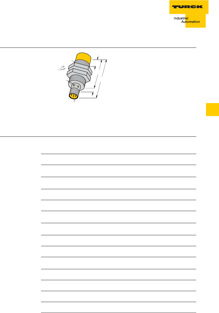
6 – 19
Description of the read-write heads
D101583 0207 BL ident
6
Technical data TN-EM30WD-H1147
Figure 17
TN-EM30WD-
H1147
This device complies with Part 15
of the FCC Rules.
Operation is subject to the
following two conditions:
(1) this device may not cause
harmful interference, and
(2) this device must accept any
interference received, including
interference that may cause
undesired operation.
Table 16:TN-
EM30WD-H1147 Type
Ident-No. TN-EM30WD-H1147
7030222
Mounting condition non-flush
Ambient temperature -25…+ 70 °C
Data transfer inductive
Output function Read/write
Operating frequency 13.56 MHz
Housing style Threaded barrel, M30 × 1.5
Housing material Metal, A4 1.4404 (AISI 316L)
Active face material Plastic, LCP-GF30
Connection Connector, M12 × 1
Vibration resistance 55 Hz (1 mm)
Shock resistance 30 g (11 ms)
Degree of protection IP67
Power ON indication Green LED
Function display Green LED, flashing
36/5
46
62
LED
M30 x 1,5
9
15
M12 x 1

Description of the read-write heads
6 – 20 D101583 0207 BL ident
Technical data TN-EM30WD-H1147/S1126
Figure 18
TN-EM30WD-
H1147/S1126
This device complies with Part 15
of the FCC Rules.
Operation is subject to the
following two conditions:
(1) this device may not cause
harmful interference, and
(2) this device must accept any
interference received, including
interference that may cause
undesired operation.
Table 17:
TN-EM30
WD-H1147/S1126
Type
Ident-No. TN-EM30WD-H1147/S1126
7030226
Mounting condition non-flush
Ambient temperature -25…+ 70 °C
Data transfer inductive
Output function Read/write
Operating frequency 13.56 MHz
Housing style Threaded barrel, M30 × 1.5
Housing material Metal, A4 1.4404 (AISI 316L)
Active face material Plastic, LCP-GF30
Connection Connector, M12 × 1
Vibration resistance 55 Hz (1 mm)
Shock resistance 30 g (11 ms)
Degree of protection IP67
Power ON indication Green LED
Function display Green LED, flashing
36/5
46
62
LED
M30 x 1,5
9
15
M12 x 1

6 – 21
Description of the read-write heads
D101583 0207 BL ident
6
Technical data TN-CK40-H1147
Figure 19
TN-CK40-H1147 This device complies with Part 15
of the FCC Rules.
Operation is subject to the
following two conditions:
(1) this device may not cause
harmful interference, and
(2) this device must accept any
interference received, including
interference that may cause
undesired operation.
Table 18:
TN-CK40-H1147 Type
Ident-No. TN-CK40-H1147
7030006
Mounting condition
non-flush, flush installation
Ambient temperature -25…+ 70 °C
Data transfer inductive
Output function Read/write
Operating frequency 13.56 MHz
Housing style Rectangular, CK40
Housing material Plastic, PBT-GF30-V0, black
Active face material Plastic, PBT-GF30-V0, yellow
Connection Connector, M12 × 1
Vibration resistance 55 Hz (1 mm)
Shock resistance 30 g (11 ms)
Degree of protection IP67
Power ON indication Green LED
Function display Green LED, flashing
40
40
30
M12 x 1
20
ø 5,3
46
5,3 x 7,3
65
60
LED

Description of the read-write heads
6 – 22 D101583 0207 BL ident
Technical data TN-CK40-H1147/S1126
Figure 20
TN-CK40-H1147 This device complies with Part 15
of the FCC Rules.
Operation is subject to the
following two conditions:
(1) this device may not cause
harmful interference, and
(2) this device must accept any
interference received, including
interference that may cause
undesired operation.
Table 19:
TN-CK40
-H1147/S1126 Type
Ident-No. TN-CK40-H1147/S1126
7030216
Mounting condition
non-flush, flush installation
Ambient temperature -25…+ 70 °C
Data transfer inductive
Output function Read/write
Operating frequency 13.56 MHz
Housing style Rectangular, CK40
Housing material Plastic, PBT-GF30-V0, black
Active face material Plastic, PBT-GF30-V0, yellow
Connection Connector, M12 × 1
Vibration resistance 55 Hz (1 mm)
Shock resistance 30 g (11 ms)
Degree of protection IP67
Power ON indication Green LED
Function display Green LED, flashing
40
40
30
M12 x 1
20
ø 5,3
46
5,3 x 7,3
65
60
LED

6 – 23
Description of the read-write heads
D101583 0207 BL ident
6
Technical data TN-Q80-H1147
Figure 21
TN-Q80-H1147 This device complies with Part 15
of the FCC Rules.
Operation is subject to the
following two conditions:
(1) this device may not cause
harmful interference, and
(2) this device must accept any
interference received, including
interference that may cause
undesired operation.
Table 20:
TN-Q80-H1147 Type
Ident-No. TN-Q80-H1147
7030007
Mounting condition
non-flush, installation on metal possible
Ambient temperature -25…+ 70 °C
Data transfer inductive
Output function Read/write
Operating frequency 13.56 MHz
Housing style Q80
Housing material Plastic, PBT-GF30-V0, yellow
Active face material Plastic, PBT-GF30-V0, yellow
Connection Connector, M12 × 1
Vibration resistance 55 Hz (1 mm)
Shock resistance 30 g (11 ms)
Degree of protection IP67
Power ON indication Green LED
Function display Green LED, flashing
27,2
40
80
ø 5,3
92
65
LED
114
M12 x 1

Description of the read-write heads
6 – 24 D101583 0207 BL ident
Technical data TN-Q80-H1147/S1126
Figure 22
TN-Q80-H1147/
S1126
This device complies with Part 15
of the FCC Rules.
Operation is subject to the
following two conditions:
(1) this device may not cause
harmful interference, and
(2) this device must accept any
interference received, including
interference that may cause
undesired operation.
Table 21:TN-Q80-
H1147/S1126 Type
Ident-No. TN-Q80-H1147/S1126
7030217
Mounting condition
non-flush, installation on metal possible
Ambient temperature -25…+ 70 °C
Data transfer inductive
Output function Read/write
Operating frequency 13.56 MHz
Housing style Q80
Housing material Plastic, PBT-GF30-V0, yellow
Active face material Plastic, PBT-GF30-V0, yellow
Connection Connector, M12 × 1
Vibration resistance 55 Hz (1 mm)
Shock resistance 30 g (11 ms)
Degree of protection IP67
Power ON indication Green LED
Function display Green LED, flashing
27,2
40
80
ø 5,3
92
65
LED
114
M12 x 1

6 – 25
Description of the read-write heads
D101583 0207 BL ident
6
Technical data TNER-Q80-H1147
Figure 23
TNER-Q80-
H1147
This device complies with Part 15
of the FCC Rules.
Operation is subject to the
following two conditions:
(1) this device may not cause
harmful interference, and
(2) this device must accept any
interference received, including
interference that may cause
undesired operation.
Table 22:TNER-
Q80-H1147 Type
Ident-No. TNER-Q80-H1147
7030211
Mounting condition
non-flush, installation on metal possible
Ambient temperature -25…+ 70 °C
Data transfer inductive
Output function Read/write
Operating frequency 13.56 MHz
Housing style Q80
Housing material Plastic, PBT-GF30-V0, yellow
Active face material Plastic, PBT-GF30-V0, yellow
Connection Connector, M12 × 1
Vibration resistance 55 Hz (1 mm)
Shock resistance 30 g (11 ms)
Degree of protection IP67
Power ON indication Green LED
Function display Green LED, flashing
27,2
40
80
ø 5,3
92
65
LED
114
M12 x 1

Description of the read-write heads
6 – 26 D101583 0207 BL ident
Technical data TNLR-Q80-H1147
Figure 24
TNLR-Q80-H1147 This device complies with Part 15
of the FCC Rules.
Operation is subject to the
following two conditions:
(1) this device may not cause
harmful interference, and
(2) this device must accept any
interference received, including
interference that may cause
undesired operation.
Table 23:TNLR-
Q80-H1147 Type
Ident-No. TNLR-Q80-H1147
7030230
Mounting condition
non-flush, installation on metal possible
Ambient temperature -25…+ 70 °C
Data transfer inductive
Output function Read/write
Operating frequency 13.56 MHz
Housing style Q80
Housing material Plastic, PBT-GF30-V0, yellow
Active face material Plastic, PBT-GF30-V0, yellow
Connection Connector, M12 × 1
Vibration resistance 55 Hz (1 mm)
Shock resistance 30 g (11 ms)
Degree of protection IP67
Power ON indication Green LED
Function display Green LED, flashing
27,2
40
80
ø 5,3
92
65
LED
114
M12 x 1

6 – 27
Description of the read-write heads
D101583 0207 BL ident
6
Technical data TNLR-Q80-H1147/S1126
Figure 25
TNLR-Q80-
H1147/S1126
This device complies with Part 15
of the FCC Rules.
Operation is subject to the
following two conditions:
(1) this device may not cause
harmful interference, and
(2) this device must accept any
interference received, including
interference that may cause
undesired operation.
Table 24:TNLR-
Q80-H1147/S1126
Type
Ident-No. TNLR-Q80-H1147/S1126
7030219
Mounting condition
non-flush, installation on metal possible
Ambient temperature -25…+ 70 °C
Data transfer inductive
Output function Read/write
Operating frequency 13.56 MHz
Housing style Q80
Housing material Plastic, PBT-GF30-V0, yellow
Active face material Plastic, PBT-GF30-V0, yellow
Connection Connector, M12 × 1
Vibration resistance 55 Hz (1 mm)
Shock resistance 30 g (11 ms)
Degree of protection IP67
Power ON indication Green LED
Function display Green LED, flashing
27,2
40
80
ø 5,3
92
65
LED
114
M12 x 1

Description of the read-write heads
6 – 28 D101583 0207 BL ident
Technical data TN-S32XL-H1147
Figure 26
TN-S32XL-H1147 This device complies with Part
15 of the FCC Rules.
Operation is subject to the
following two conditions:
(1) this device may not cause
harmful interference, and
(2) this device must accept any
interference received, including
interference that may cause
undesired operation.
Table 25:
TN-S32XL-H1147 Type
Ident-No. TN-S32XL-H1147
7030008
Mounting condition
non-flush, installation on metal possible
Ambient temperature -25…+ 70 °C
Data transfer inductive
Output function Read/write
Operating frequency 13.56 MHz
Housing style Ring sensor, S32
Housing material Plastic, ABS, yellow
Ring internal diameter 100 mm
Connection Connector, M12 × 1
Vibration resistance 55 Hz (1 mm)
Shock resistance 30 g (11 ms)
Degree of protection IP67
Power ON indication Green LED
Function display Green LED, flashing
ø 100
120
32
M12 x 1
LED
60
137,5
ø
6,5
111,25 180
Pot.
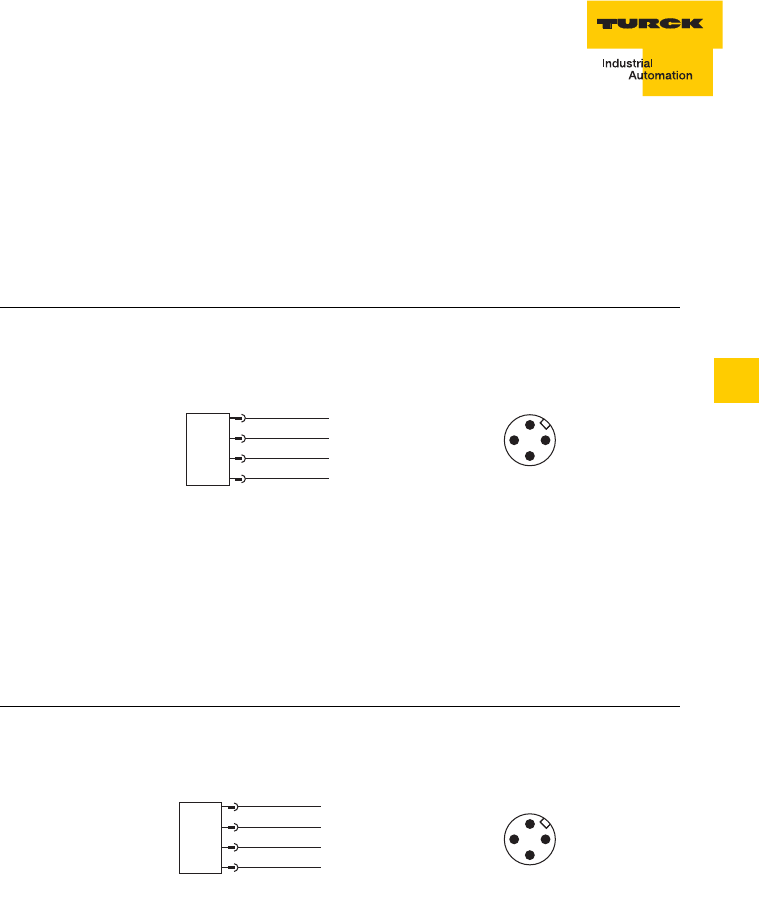
6 – 29
Description of the read-write heads
D101583 0207 BL ident
6
Connection of the read-write heads
The read-write heads are connected via an M12 × 1 connector with
the BLident interface module. The power supply (24 V DC) and
function are implemented via the BLident interface module.
The standard cordsets feature the wiring diargam shown in figure 27.
The special cordsets .../S2502 feature a different wiring diagram (see
figure 28).
Figure 27
Wiring diagram,
standard cables
Figure 28:
Wiring diagram,
special cordsets
+
1 BN
3 BU
4 WH
2 BK Data
Data
3
2
4
1
+
1 RD
3 BK
4 WH
2 BU Data
Data
3
2
4
1

Description of the read-write heads
6 – 30 D101583 0207 BL ident

7 – 1
Operating data
D101583 0207 BL ident
7
7 Description of the read-write heads with
corresponding data carriers
Notes for the operating data.............................................................................2
Operating data
TB-M18-H1147............................................................................................3
TB-EM18WD-H1147 ...................................................................................3
TB-M18-H1147/S1126................................................................................4
TB-EM18WD-H1147/S1126........................................................................4
TN-M18-H1147 ...........................................................................................5
TN-EM18WD-H1147 ...................................................................................5
TN-M18-H1147/S1126................................................................................6
TN-EM18WD-H1147/S1126........................................................................6
TB-M30-H1147............................................................................................7
TB-EM30WD-H1147 ...................................................................................8
TB-M30-H1147/S1126................................................................................9
TB-EM30WD-H1147/S1126......................................................................10
TN-M30-H1147 .........................................................................................11
TN-EM30WD-H1147 .................................................................................12
TN-M30-H1147/S1126..............................................................................13
TN-EM30WD-H1147/S1126......................................................................14
TN-CK40-H1147........................................................................................15
TN-CK40-H1147/S1126............................................................................16
TN-Q80-H1147..........................................................................................17
TN-Q80-H1147/S1126 ..............................................................................18
TNER-Q80-H1147.....................................................................................19
TNLR-Q80-H1147 .....................................................................................20
TNLR-Q80-H1147/S1126..........................................................................21
TN-S32XL-H1147......................................................................................22

Operating data
7 – 2 D101583 0207 BL ident
Notes for the operating data
The operating data are sufficient for the fundamental specification of a system.
They provide a simplified analysis of the overtravel distances which can be
found in chapter 8.
If a more detailed examination of the performance of read-write heads is
necessary, the corresponding overtravel distances can be consulted.
Note
Remember that the auxiliary factors, e.g. the influence of metals, are
not considered for the sake of simplification.
Corresponding tests should be undertaken before commissioning.

7 – 3
Operating data
D101583 0207 BL ident
7
Operating data for read-write head
– TB-M18-H1147
– TB-EM18WD-H1147
Table 1:
Operating data
TB-...M18...-
H1147
Corresponding
data carrier Read-write distance
Recommended
[mm] Maximum
[mm]
TW-R16-B128 613
TW-R20-B128 613
TW-R20-K2 512
TW-I14-B128 613
TW-L43-43-F-B128 15 30
TW-L82-49-P-B128 15 23

Operating data
7 – 4 D101583 0207 BL ident
Operating data for read-write head
– TB-M18-H1147/S1126
– TB-EM18WD-H1147/S1126
Table 2:
Operating data
TB-...M18...-
H1147/S1126
Corresponding
data carrier Read-write distance
Recommended
[mm] Maximum
[mm]
TW-R16-B64 613
TW-R16-B128 613
TW-R20-B128 613
TW-I14-B128 613
TW-L43-43-F-B128 15 30
TW-L82-49-P-B128 15 23

7 – 5
Operating data
D101583 0207 BL ident
7
Operating data for read-write head
– TN-M18-H1147
– TN-EM18WD-H1147
Table 3:
Operating data
TN-...M18...-
H1147
Corresponding
data carrier Read-write distance
Recommended
[mm] Maximum
[mm]
TW-R16-B128 12 23
TW-R20-B128 10 22
TW-R30-B128 10 25
TW-R50-B128 20 41
TW-R20-K2 12 20
TW-R30-K2 16 31
TW-R50-K2 12 30
TW-I14-B128 10 22
TW-L43-43-F-B128 25 45
TW-L82-49-P-B128 20 40

Operating data
7 – 6 D101583 0207 BL ident
Operating data for read-write head
– TN-M18-H1147/S1126
– TN-EM18WD-H1147/S1126
Table 4:
Operating data
TN-...M18...-
H1147/S1126
Corresponding
data carrier Read-write distance
Recommended
[mm] Maximum
[mm]
TW-R16-B64 613
TW-R16-B128 613
TW-R20-B128 613
TW-R20-K2 512
TW-I14-B128 613
TW-L43-43-F-B128 15 30
TW-L82-49-P-B128 15 23

7 – 7
Operating data
D101583 0207 BL ident
7
Operating data for read-write head
– TB-M30-H1147
Table 5:
Operating data
TB-M30-H1147
Corresponding
data carrier Read-write distance
Recommended
[mm] Maximum
[mm]
TW-R16-B64 12 23
TW-R16-B128 12 23
TW-R20-B128 15 27
TW-R30-B128 13 30
TW-R50-B128 20 43
TW-R20-K2 15 22
TW-R30-K2 15 27
TW-R50-K2 15 33
TW-R50-90-HT-B128 510
TW-I14-B128 15 27
TW-L43-43-F-B128 25 42
TW-L82-49-P-B128 20 43

Operating data
7 – 8 D101583 0207 BL ident
Operating data for read-write head
– TB-EM30WD-H1147
Table 6:
Operating data
TB-...M30...-
H1147
Corresponding
data carrier Read-write distance
Recommended
[mm] Maximum
[mm]
TW-R16-B128 12 23
TW-R20-B128 15 27
TW-R30-B128 13 30
TW-R50-B128 20 43
TW-R20-K2 15 22
TW-R30-K2 15 27
TW-R50-K2 15 33
TW-R50-90-HT-B128 510
TW-I14-B128 15 27
TW-L43-43-F-B128 25 42
TW-L82-49-P-B128 20 43

7 – 9
Operating data
D101583 0207 BL ident
7
Operating data for read-write head
– TB-M30-H1147/S1126
Table 7:
Operating data
TB-M30-H1147/
S1126
Corresponding
data carrier Read-write distance
Recommended
[mm] Maximum
[mm]
TW-R16-B128 12 23
TW-R20-B128 15 27
TW-R30-B128 13 30
TW-R50-B128 20 43
TW-R22-HT-B64 517
TW-R50-90-HT-B128 510
TW-I14-B128 15 27
TW-L43-43-F-B128 25 42
TW-L82-49-P-B128 20 43

Operating data
7 – 10 D101583 0207 BL ident
Operating data for read-write head
– TB-EM30WD-H1147/S1126
Table 8:
Operating data
TB-...M30...-
H1147/S1126
Corresponding
data carrier Read-write distance
Recommended
[mm] Maximum
[mm]
TW-R16-B64 12 23
TW-R16-B128 12 23
TW-R20-B128 15 27
TW-R30-B128 13 30
TW-R50-B128 20 43
TW-R22-HT-B64 517
TW-R50-90-HT-B128 510
TW-I14-B128 15 27
TW-L43-43-F-B128 25 42
TW-L82-49-P-B128 20 43

7 – 11
Operating data
D101583 0207 BL ident
7
Operating data for read-write head
– TN-M30-H1147
Table 9:
Operating data
TN-M30-H1147
Corresponding
data carrier Read-write distance
Recommen-ded
[mm] Maximum
[mm]
TW-R16-B128 20 38
TW-R20-B128 22 40
TW-R30-B128 22 43
TW-R50-B128 40 72
TW-R20-K2 17 31
TW-R30-K2 23 42
TW-R50-K2 30 58
TW-R50-90-HT-B128 19 39
TW-R50-90-HT-K2 12 25
TW-I14-B128 22 40
TW-L43-43-F-B128 30 64
TW-L82-49-P-B128 30 65

Operating data
7 – 12 D101583 0207 BL ident
Operating data for read-write head
– TN-EM30WD-H1147
Table 10:
Operating data
TN-...M30...-
H1147
Corresponding
data carrier Read-write distance
Recommended
[mm] Maximum
[mm]
TW-R16-B128 20 38
TW-R20-B128 22 40
TW-R30-B128 22 43
TW-R50-B128 40 72
TW-R20-K2 17 31
TW-R30-K2 23 42
TW-R50-K2 30 58
TW-R50-90-HT-B128 19 39
TW-R50-90-HT-K2 12 25
TW-I14-B128 22 40
TW-L43-43-F-B128 30 64
TW-L82-49-P-B128 30 65

7 – 13
Operating data
D101583 0207 BL ident
7
Operating data for read-write head
– TN-M30-H1147/S1126
Table 11:
Operating data
TN-M30-H1147/
S1126
Corresponding
data carrier Read-write distance
Recommended
[mm] Maximum
[mm]
TW-R16-B64 20 38
TW-R16-B128 20 38
TW-R20-B128 22 40
TW-R30-B128 22 43
TW-R50-B128 40 72
TW-R22-HT-B64 12 30
TW-R50-90-HT-B128 19 39
TW-I14-B128 22 40
TW-L43-43-F-B128 30 64
TW-L82-49-P-B128 30 65

Operating data
7 – 14 D101583 0207 BL ident
Operating data for read-write head
– TN-EM30WD-H1147/S1126
Table 12:
Operating data
TN-EM30WD-
H1147/S1126
Corresponding
data carrier Read-write distance
Recommended
[mm] Maximum
[mm]
TW-R16-B64 20 38
TW-R16-B128 20 38
TW-R20-B128 22 40
TW-R30-B128 22 43
TW-R50-B128 40 72
TW-R22-HT-B64 12 30
TW-R50-90-HT-B128 19 39
TW-I14-B128 22 40
TW-L43-43-F-B128 30 64
TW-L82-49-P-B128 30 65

7 – 15
Operating data
D101583 0207 BL ident
7
Operating data for read-write head
– TN-CK40-H1147
Table 13:
Operating data
TN-CK40-H1147
Corresponding
data carrier Read-write distance
Recommended
[mm] Maximum
[mm]
TW-R16-B64 28 50
TW-R16-B128 28 50
TW-R20-B128 30 50
TW-R30-B128 30 53
TW-R50-B128 45 85
TW-R20-K2 22 40
TW-R30-K2 30 55
TW-R50-K2 38 81
TW-R50-90-HT-B128 26 52
TW-R50-90-HT-K2 24 48
TW-I14-B128 30 50
TW-L43-43-F-B128 50 90
TW-L82-49-P-B128 50 96

Operating data
7 – 16 D101583 0207 BL ident
Operating data for read-write head
– TN-CK40-H1147/S1126
Table 14:
Operating data
TN-CK40-H1147/
S1126
Corresponding
data carrier Read-write distance
Recommended
[mm] Maximum
[mm]
TW-R16-B64 28 50
TW-R16-B128 28 50
TW-R20-B128 30 50
TW-R30-B128 30 53
TW-R50-B128 45 85
TW-R22-HT-B64 20 40
TW-R50-90-HT-B128 26 52
TW-I14-B128 30 50
TW-L43-43-F-B128 50 90
TW-L82-49-P-B128 50 96

7 – 17
Operating data
D101583 0207 BL ident
7
Operating data for read-write head
– TN-Q80-H1147
Table 15:
Operating data
TN-Q80-H1147
Corresponding
data carrier Read-write distance
Recommen-ded
[mm] Maximum
[mm]
TW-R16-B128 20 52
TW-R20-B128 35 65
TW-R30-B128 35 72
TW-R50-B128 65 118
TW-R20-K2 25 52
TW-R30-K2 35 67
TW-R50-K2 50 100
TW-R50-90-HT-B128 42 85
TW-R50-90-HT-K2 33 67
TW-I14-B128 35 65
TW-L43-43-F-B128 60 115
TW-L82-49-P-B128 65 128

Operating data
7 – 18 D101583 0207 BL ident
Operating data for read-write head
– TN-Q80-H1147/S1126
Table 16:
Operating data
TN-Q80-H1147/
S1126
Corresponding
data carrier Read-write distance
Recommended
[mm] Maximum
[mm]
TW-R16-B64 20 52
TW-R16-B128 20 52
TW-R20-B128 35 65
TW-R30-B128 35 72
TW-R50-B128 65 118
TW-R20-K2 25 52
TW-R22-HT-B64 25 55
TW-R50-90-HT-B128 42 85
TW-I14-B128 35 65
TW-L43-43-F-B128 60 115
TW-L82-49-P-B128 65 128

7 – 19
Operating data
D101583 0207 BL ident
7
Operating data for read-write head
– TNER-Q80-H1147
Table 17:
Operating data
TNER-Q80-
H1147
Corresponding
data carrier Read-write distance
Recommended
[mm] Maximum
[mm]
TW-R16-B64 20 52
TW-R22-HT-B64 35 70

Operating data
7 – 20 D101583 0207 BL ident
Operating data for read-write head
– TNLR-Q80-H1147
Table 18:
Operating data
TNLR-Q80-H1147
Corresponding
data carrier Read-write distance
Recommended
[mm] Maximum
[mm]
TW-R16-B128 50 85
TW-R20-B128 50 88
TW-R30-B128 60 115
TW-R50-B128 80 165
TW-R20-K2 40 75
TW-R30-K2 60 98
TW-R50-K2 90 144
TW-R50-90-HT-B128 60 135
TW-R50-90-HT-K2 60 114
TW-I14-B128 50 85
TW-L43-43-F-B128 90 155
TW-L82-49-P-B128 90 168

7 – 21
Operating data
D101583 0207 BL ident
7
Operating data for read-write head
– TNLR-Q80-H1147/S1126
Table 19:
Operating data
TNLR-Q80-
H1147/S1126
Corresponding
data carrier Read-write distance
Recommended
[mm] Maximum
[mm]
TW-R20-B128 50 88
TW-R30-B128 60 115
TW-R50-B128 80 165
TW-R22-HT-B64 39 74
TW-R50-90-HT-B128 60 135
TW-I14-B128 50 85
TW-L43-43-F-B128 90 155
TW-L82-49-P-B128 90 168

Operating data
7 – 22 D101583 0207 BL ident
Operating data for read-write head
– TN-S32XL-H1147
Table 20:
Operating data
TN-S32XL-H1147
Corresponding
data carrier Read-write distance
Recommen-ded
[mm] Maximum
[mm]
TW-R16-B128 20 67
TW-R20-B128 36 72
TW-R30-B128 30 80
TW-R50-B128 80 150
TW-R20-K2 32 64
TW-R30-K2 30 78
TW-R50-K2 60 128
TW-R50-90-HT-B128 58 1117
TW-R50-90-HT-K2 42 85
TW-I14-B128 36 72
TW-L43-43-F-B128 80 140
TW-L82-49-P-B128 80 160

8 – 1
Overtravel ranges
D101583 0207 BL ident
8
8 Description of the read-write heads with
corresponding data carriers
Notes for the overtravel distances....................................................................3
Overtravel distance read-write head – housing style M18
TN-...M18...-H1147... with data carrier TW-R16-B128. ..............................5
TB-...M18...-H1147... with data carrier TW-R16-B128 ...............................5
TN-...M18...-H1147... with data carrier TW-R20-B128. ..............................6
TB-...M18...-H1147... with data carrier TW-R20-B128. ..............................6
TN-...M18...-H1147... with data carrier TW-R30-B128...............................7
TB-...M18...-H1147... with data carrier TW-R30-B128 ...............................7
TN-...M18...-H1147... with data carrier TW-R50-B128, ..............................8
TN-...M18...-H1147... with data carrier TW-R20-K2 ...................................8
TB-...M18...-H1147... with data carrier TW-R20-K2....................................9
TN-...M18...-H1147... with data carrier TW-R30-K2 ...................................9
TN-...M18...-H1147... with data carrier TW-R50-K2 .................................10
TN-...M18...-H1147... with data carrier TW-L43-43-F-B128.....................10
TB-...M18...-H1147... with data carrier TW-L43-43-F-B128.....................11
TN-...M18...-H1147... with data carrier TW-L82-49-P-B128.....................11
TB-...M18...-H1147... with data carrier TW-L82-49-P-B128.....................12
Overtravel distance read-write head – housing style M30
TN-...M30...-H1147... with data carrier TW-R16-B128.............................12
TB-...M30...-H1147... with data carrier TW-R16-B128 .............................13
TN-...M30...-H1147... with data carrier TW-R20-B128.............................13
TB-...M30...-H1147... with data carrier TW-R20-B128 .............................14
TN-...M30...-H1147... with data carrier TW-R30-B128.............................14
TB-...M30...-H1147... with data carrier TW-R30-B128 .............................15
TN-...M30...-H1147... with data carrier TW-R50-B128.............................15
TB-...M30...-H1147... with data carrier TW-R50-B128 ............................16
TN-...M30...-H1147... with data carrier TW-R20-K2 .................................16
TB-...M30...-H1147... with data carrier TW-R20-K2..................................17
TN-...M30...-H1147... with data carrier TW-R30-K2 .................................17
TB-...M30...-H1147... with data carrier TW-R30-K2 .................................18
TN-...M30...-H1147... with data carrier TW-R50-K2 .................................18
TB-...M30...-H1147... with data carrier TW-R50-K2..................................19
TN-...M30...-H1147... with data carrier TW-L43-43-F-B128.....................19
TB-...M30...-H1147... with data carrier TW-L43-43-F-B128.....................20
TN-...M30...-H1147... with data carrier TW-L82-49-P-B128.....................20
TB-...M30...-H1147... with data carrier TW-L82-49-P-B128.....................21
Overtravel ranges
8 – 2 D101583 0207 BL ident
Overtravel distance read-write head – housing style Q40
TN-CK40-H1147... with data carrier TW-R16-B128 .................................21
TN-CK40-H1147... with data carrier TW-R20-B128 .................................22
TN-CK40-H1147... with data carrier TW-R30-B128 .................................22
TN-CK40-H1147... with data carrier TW-R50-B128 .................................23
TN-CK40-H1147... with data carrier TW-R20-K2......................................23
TN-CK40-H1147... with data carrier TW-R30-K2......................................24
TN-CK40-H1147... with data carrier TW-R50-K2......................................24
TN-CK40-H1147... with data carrier TW-L43-43-F-B128.........................25
TN-CK40-H1147... with data carrier TW-L82-49-P-B128.........................25
Overtravel distance read-write head – housing style Q80
TN-Q80-H1147 with data carrier TW-R16-B128.......................................26
TN-Q80-H1147 with data carrier TW-R20-B128.......................................26
TN-Q80-H1147 with data carrier TW-R30-B128.......................................27
TN-Q80-H1147 with data carrier TW-R50-B128.......................................27
TN-Q80-H1147 with data carrier TW-R20-K2...........................................28
TN-Q80-H1147 with data carrier TW-R30-K2...........................................28
TN-Q80-H1147 with data carrier TW-R50-K2...........................................29
TN-Q80-H1147 with data carrier TW-L43-43-F-B128 ..............................29
TN-Q80-H1147 with data carrier TW-L82-49-P-B128..............................30
TNLR-Q80-H1147 with data carrier TW-R16-B128..................................30
TNLR-Q80-H1147 with data carrier TW-R20-B128..................................31
TNLR-Q80-H1147 with data carrier TW-R20-K2 ......................................31
TNLR-Q80-H1147 with data carrier TW-R30-B128..................................32
TNLR-Q80-H1147 with data carrier TW-R30-K2 ......................................32
TNLR-Q80-H1147 with data carrier TW-R50-B128..................................33
TNLR-Q80-H1147 with data carrier TW-R50-K2 ......................................33
TNLR-Q80-H1147 with data carrier TW-L43-43-F-B128..........................34
Overtravel distance read-write head – housing style S32
TN-S32XL-H1147 with data carrier TW-R16-B128...................................35
TN-S32XL-H1147 with data carrier TW-R30-B128...................................35
TN-S32XL-H1147 with data carrier TW-R50-B128...................................36
TN-S32XL-H1147 with data carrier TW-R30-K2.......................................36
TN-S32XL-H1147 with data carrier TW-R50-K2.......................................37
TN-S32XL-H1147 with data carrier TW-L43-43-F-B128...........................37
TN-S32XL-H1147 with data carrier TW-L82-49-P-B128..........................38

8 – 3
Overtravel ranges
D101583 0207 BL ident
8
Notes for the overtravel distances
The following characteristic curves indicate the overtravel distances
of the different read-write heads with the data carriers used.
The characteristic curves are not just dependent on the used read-
write head and the data carrier, but also on the memory type of the
data carrier (EEPROM or FRAM) (see Overview table 1).
The characteristic curves of the high temperature data carriers TW-
50-90-HT-B128 and TW-50-90-HT-K2 are not listed separately.
They deviate from those listed on the following pages only in the fact
that the
curves must simply be offset downwards by 30mm.
.

Overtravel ranges
8 – 4 D101583 0207 BL ident
Table 1:
Data carrier
memory type
Type High-
t
emperature
resistant
Memory
size Memory
type
TW-R16-B64 –64 Byte EEPROM
TW-R16-B128 –128 Byte EEPROM
TW-R20-B128 –128 Byte EEPROM
TW-R30-B128 –128 Byte EEPROM
TW-R50-B128 –128 Byte EEPROM
TW-R20-K2 –2 kByte FRAM
TW-R30-K2 –2 kByte FRAM
TW-R50-K2 –2 kByte FRAM
TW-R22-HT-B64 ✔64 Byte EEPROM
TW-R50-90-HT-B128 ✔128 Byte EEPROM
TW-R50-90-HT-K2 ✔2 kByte FRAM
TW-I14-B128 –128 Byte EEPROM
TW-L43-43-F-B128 –128 Byte EEPROM
TW-L82-49-P-B128 –128 Byte EEPROM
8 – 5
Overtravel ranges
D101583 0207 BL ident
8
Read-write head TN-...M18...-H1147... overtravel distance with data carrier TW-R16-B128.
Read-write head TB-...M18...-H1147... overtravel distance with data carrier TW-R16-B128.
Figure 1
Overtravel
distance TN-
...M18...-H1147...
with TW-R16-
B128
Figure 2
Overtravel
distance TB-
...M18...-H1147...
with TW-R16-
B128
0
5
10
15
20
25
30
0 5 10 15 20 25
mm
mm
0
2
4
6
8
10
12
14
16
18
0 5 10 15
mm
mm
Overtravel ranges
8 – 6 D101583 0207 BL ident
Read-write head TN-...M18...-H1147... overtravel distance with data carrier TW-R20-B128
.
Read-write head TB-...M18...-H1147... overtravel distance with data carrier TW-R20-B128.
Figure 3
Overtravel
distance TN-
....M18...-H1147...
with TW-R20-
B128
Figure 4
Overtravel
distance TB-
...M18...-H1147...
with TW-R20-
B128
0
5
10
15
20
25
0 5 10 15 20 25 30
mm
mm
0
2
4
6
8
10
12
14
16
024681012
mm
mm
8 – 7
Overtravel ranges
D101583 0207 BL ident
8
Read-write head TN-...M18...-H1147... overtravel distance with data carrier TW-R30-B128.
Read-write head TB-...M18...-H1147... overtravel distance with data carrier TW-R30-B128.
Figure 5
Overtravel
distance TN-
...M18...-H1147...
with TW-R30-
B128
Figure 6
Overtravel
distance TB-
...M18...-H1147...
with TW-R30-
B128
0
5
10
15
20
25
30
0 5 10 15 20 25 30
mm
mm
0
2
4
6
8
10
12
14
16
18
024681012
mm
mm
Overtravel ranges
8 – 8 D101583 0207 BL ident
Read-write head TN-...M18...-H1147... overtravel distance with data carrier TW-R50-B128.
,
Read-write head TN-...M18...-H1147... overtravel distance with data carrier TW-R20-K2
,
Figure 7
Overtravel
distance TN-
...M18...-H1147...
with TW-R50-
B128
Figure 8
Overtravel
distance TN-
...M18...-H1147...
with TW-R20-K2
0
5
10
15
20
25
30
35
40
45
0 102030405060
mm
mm
0
5
10
15
20
25
0 5 10 15 20mm
mm

8 – 9
Overtravel ranges
D101583 0207 BL ident
8
Read-write head TB-...M18...-H1147... overtravel distance with data carrier TW-R20-K2
,
Read-write head TN-...M18...-H1147... overtravel distance with data carrier TW-R30-K2
Figure 9
Overtravel
distance TB-
...M18...-H1147...
with TW-R20-K2
Figure 10
Overtravel
distance TN-
....M18...-H1147...
with TW-R30-K2
-2
0
2
4
6
8
10
12
14
0246810
mm
mm
0
5
10
15
20
25
30
35
0 5 10 15 20 25 30
mm
mm
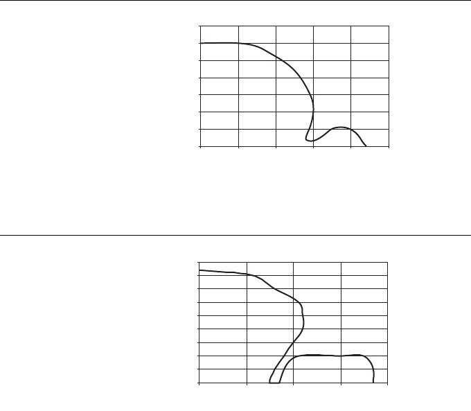
Overtravel ranges
8 – 10 D101583 0207 BL ident
Read-write head TN...-...M18...-H1147... overtravel distance with data carrier TW-R50-K2
Read-write head TN-...M18..-H1147... overtravel distance with data carrier TW-L43-43-F-B128
Figure 11
Overtravel
distance TN-M18-
H1147 with TW-
R50-K2
Figure 12
Overtravel dis-
tance TN-
...M18...-H1147...
with TW-L43-43-
F-B128
0
5
10
15
20
25
30
35
0 1020304050
mm
mm
mm
mm
0
10
20
30
40
0 10203040
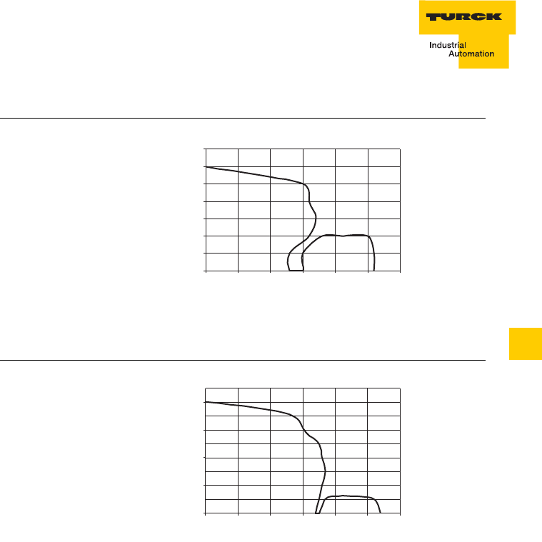
8 – 11
Overtravel ranges
D101583 0207 BL ident
8
Read-write head TB-...M18..-H1147... overtravel distance with data carrier TW-L43-43-F-B128
Read-write head TN-...M18..-H1147... overtravel distance with data carrier TW-L82-49-P-B128
Figure 13
Overtravel dis-
tance TB-
...M18...-H1147...
with TW-L43-43-
F-B128
Figure 14
Overtravel dis-
tance TN-
...M18...-H1147...
withTW-L82-49-
P-B128
mm
mm
0
5
10
15
20
25
30
35
0 5 10 15 20 25 30
mm
mm
0
10
20
30
40
0 102030405060
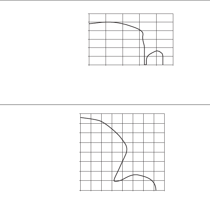
Overtravel ranges
8 – 12 D101583 0207 BL ident
Read-write head TB-...M18..-H1147... overtravel distance with data carrier TW-L82-49-P-B128
Read-write head TN-...M30...-H1147... overtravel distance with data carrier TW-R16-B128.
Figure 15
Overtravel dis-
tance TB-...M18-
...H1147... with
TW-L82-4-P-
B128
Figure 16
Overtravel
distance TN-M30-
H1147 with TW-
R16-B128
mm
mm
0
5
10
15
20
25
30
010 20 30 40 50
0
5
10
15
20
25
30
35
40
0 5 10 15 20 25 30 35 40
mm
mm
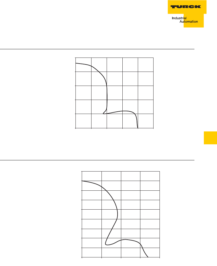
8 – 13
Overtravel ranges
D101583 0207 BL ident
8
Read-write head TB-...M30...-H1147... overtravel distance with data carrier TW-R16-B128.
Read-write head TN-...M30...-H1147... overtravel distance with data carrier TW-R20-B128.
Figure 17
Overtravel
distance TB-
...M30...-H1147...
with TW-R16-
B128
Figure 18
Overtravel
distance TN-
...M30...-H1147...
with TW-R20-
B128
0
5
10
15
20
25
0 5 10 15 20 25
mm
mm
0
5
10
15
20
25
30
35
40
45
010203040
mm
mm
Overtravel ranges
8 – 14 D101583 0207 BL ident
Read-write head TB-...M30...-H1147... overtravel distance with data carrier TW-R20-B128.
Read-write head TN-...M30...-H1147... overtravel distance with data carrier TW-R30-B128.
Figure 19
Overtravel
distance TB-
...M30...-H1147...
with TW-R20-
B128
Figure 20
Overtravel
distance TN-
...M30...-H1147...
with TW-R30-
B128
0
5
10
15
20
25
30
35
40
45
010203040
mm
mm
0
5
10
15
20
25
30
35
40
45
50
01020304050
mm
mm

8 – 15
Overtravel ranges
D101583 0207 BL ident
8
Read-write head TB-...M30...-H1147... overtravel distance with data carrier TW-R30-B128.
Read-write head TN-...M30...-H1147... overtravel distance with data carrier TW-R50-B128.
Figure 21
Overtravel
distance TB-
...M30...-H1147...
with TW-R30-
B128
Figure 22
Overtravel
distance TN-
...M30...-H1147...
with TW-R50-
B128
0
5
10
15
20
25
30
35
0 5 10 15 20 25 30
mm
mm
0
10
20
30
40
50
60
70
80
0 1020304050607080
mm
mm
Overtravel ranges
8 – 16 D101583 0207 BL ident
Read-write head TB-...M30...-H1147... overtravel distance with data carrier TW-R50-B128
Read-write head TN-...M30...-H1147... overtravel distance with data carrier TW-R20-K2
Figure 23
Overtravel
distance TB-
...M30...-H1147...
with TW-R50-
B128
Figure 24
Overtravel
distance TN-
...M30...-H1147...
with TW-R20-K2
0
5
10
15
20
25
30
35
40
45
50
0 10203040mm
mm
0
5
10
15
20
25
30
35
0 5 10 15 20 25 30 35
mm
mm
8 – 17
Overtravel ranges
D101583 0207 BL ident
8
Read-write head TB-...M30...-H1147... overtravel distance with data carrier TW-R20-K2
Read-write head TN-...M30...-H1147... overtravel distance with data carrier TW-R30-K2
Figure 25
Overtravel
distance TB-
...M30...-H1147...
with TW-R20-K2
Figure 26
Overtravel
distance TN-
...M30...-H1147...
with TW-R30-K2
0
5
10
15
20
25
0 5 10 15 20mm
mm
0
5
10
15
20
25
30
35
40
45
0 1020304050
mm
mm
Overtravel ranges
8 – 18 D101583 0207 BL ident
Read-write head TB-...M30...-H1147... overtravel distance with data carrier TW-R30-
K2
Read-write head TN-...M30...-H1147... overtravel distance with data carrier TW-R50-K2
Figure 27
Overtravel
distance TB-
...M30...-H1147...
with TW-R30-K2
Figure 28
Overtravel
distance TN-
...M30...-H1147...
with TW-R50-K2
0
5
10
15
20
25
30
0 5 10 15 20 25 30
mm
mm
0
10
20
30
40
50
60
70
0 10203040506070
mm
mm
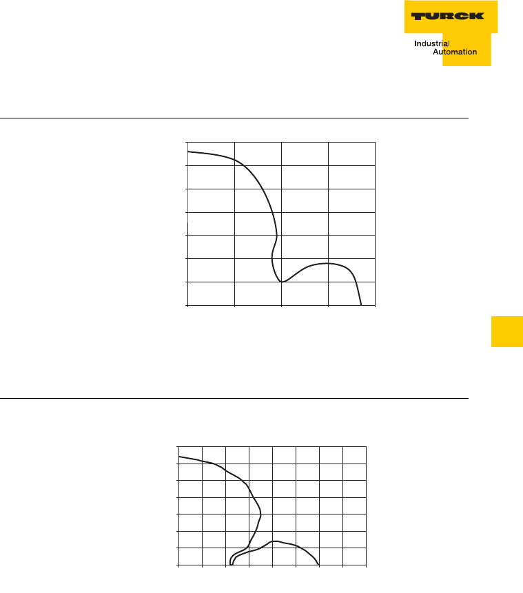
8 – 19
Overtravel ranges
D101583 0207 BL ident
8
Read-write head TB-...M30...-H1147... overtravel distance with data carrier TW-R50-K2
Read-write head TN-...M30...-H1147... overtravel distance with data carrier TW-L43-43-F-B128
Figure 29
Overtravel
distance TB-
...M30...-H1147...
with TW-R50-
…K2
Figure 30
Overtravel dis-
tance TN-
...M30...-H1147...
with TW-L43-43-
F-B128
0
5
10
15
20
25
30
35
0 10203040
mm
mm
mm
mm
0
10
20
30
40
50
60
70
020406080
10 30 50 70
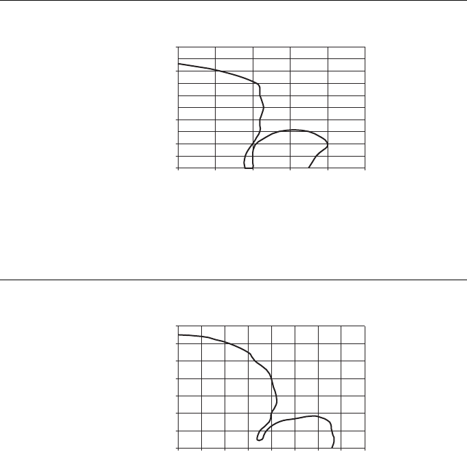
Overtravel ranges
8 – 20 D101583 0207 BL ident
Read-write head TB-...M30...-H1147... overtravel distance with data carrier TW-L43-43-F-B128
Read-write head TN-...M30...-H1147... overtravel distance with data carrier TW-L82-49-P-B128
Figure 31
Overtravel dis-
tance TB-
...M30...-H1147...
with TW-L43-43-
F-B128
Figure 32
Overtravel dis-
tance TN-
...M30...-H1147...
with TW-L82-49-
P-B128
mm
mm
0
10
20
30
40
50
0 1020304050
mm
mm
0
10
20
30
40
50
60
70
0 20406080
10 30 50 70
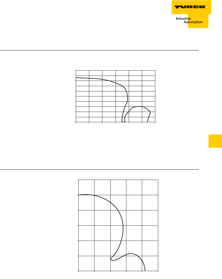
8 – 21
Overtravel ranges
D101583 0207 BL ident
8
Read-write head TB-...M30...-H1147... overtravel distance with data carrier TW-L82-49-P-B128
Read-write head TN-CK40-H1147... overtravel distance with data carrier TW-R16-B128
Figure 33
Overtravel dis-
tance TNB-M30-
H1147 with TW-
L82-49-P-B128
Figure 34
Overtravel
distance TN-
CK40-H1147...
with TW-R16-
B128
mm
mm
0
10
20
30
40
50
0 102030405060
0
10
20
30
40
50
60
010203040
50
mm
mm
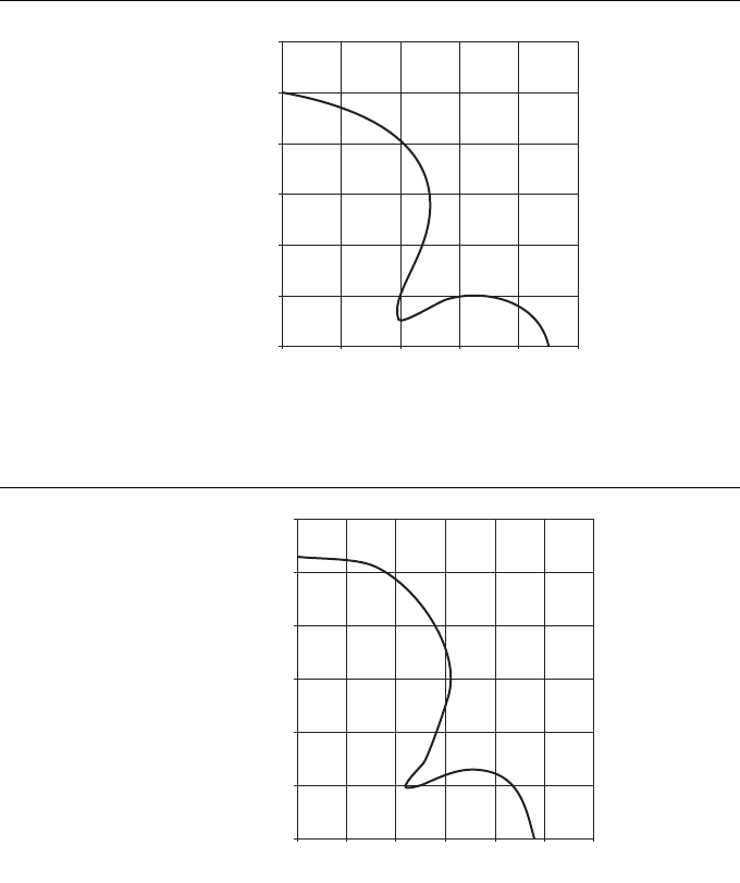
Overtravel ranges
8 – 22 D101583 0207 BL ident
Read-write head TN-CK40-H1147... overtravel distance with data carrier TW-R20-B128
Read-write head TN-CK40-H1147... overtravel distance with data carrier TW-R30-B128
Figure 35
Overtravel
distance TN-
CK40-H1147...
with TW-R20-
B128
Figure 36
Overtravel
distance TN-
CK40-H1147...
with TW-R30-
B128
0
10
20
30
40
50
60
01020304050
mm
mm
0
10
20
30
40
50
60
0 102030405060
mm
mm

8 – 23
Overtravel ranges
D101583 0207 BL ident
8
Read-write head TN-CK40-H1147... overtravel distance with data carrier TW-R50-B128
Read-write head TN-CK40-H1147... overtravel distance with data carrier TW-R20-K2
Figure 37
Overtravel
distance TN-
CK40-H1147...
with TW-R50-
B128
Figure 38
Overtravel
distance TN-
CK40-H1147...
with TW-R20-K2
0
10
20
30
40
50
60
70
80
90
020406080100
mm
mm
0
5
10
15
20
25
30
35
40
45
0 10203040mm
mm
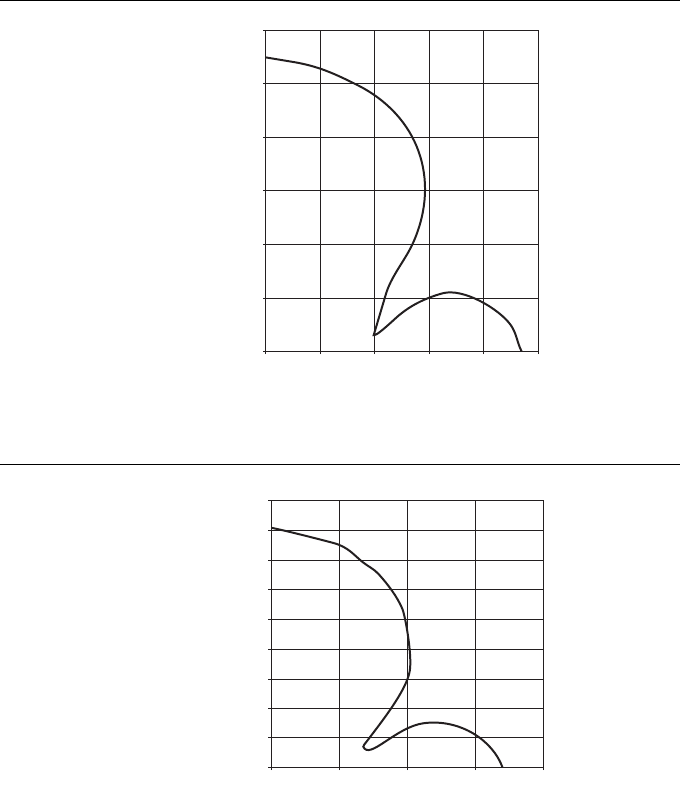
Overtravel ranges
8 – 24 D101583 0207 BL ident
Read-write head TN-CK40-H1147... overtravel distance with data carrier TW-R30-K2
Read-write head TN-CK40-H1147... overtravel distance with data carrier TW-R50-K2
Figure 39
Overtravel
distance TN-
CK40-H1147...
with TW-R30-K2
Figure 40
Overtravel
distance TN-
CK40-H1147...
with TW-R50-K2
0
10
20
30
40
50
60
0 1020304050mm
mm
0
10
20
30
40
50
60
70
80
90
0 20406080
mm
mm

8 – 25
Overtravel ranges
D101583 0207 BL ident
8
Read-write head TN-CK40-H1147... overtravel distance with data carrier TW-L43-43-F-B128
Read-write head TN-CK40-H1147... overtravel distance with data carrier TW-L82-49-P-B128
Figure 41:
Overtravel
distance TN-
CK40-H1147...
with TW-L82-49-
P-B128
Figure 42
Overtravel dis-
tance TN-CK40-
H1147... with TW-
L82-49-P-B128
0
10
010
mm
mm
20 30 40 50 60 70 80
20
30
40
50
60
70
80
90
100
mm
mm
0
20
40
60
80
100
120
0 20406080100
10 30 50 70 90
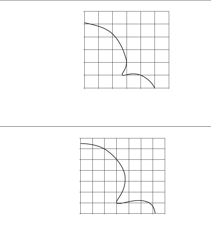
Overtravel ranges
8 – 26 D101583 0207 BL ident
Read-write head TN-Q80-H1147 overtravel distance with data carrier TW-R16-B128
Read-write head TN-Q80-H1147 overtravel distance with data carrier TW-R20-B128
Figure 43
Overtravel
distance TN-Q80-
H1147 with TW-
R16-B128
Figure 44
Overtravel
distance TN-Q80-
H1147 with TW-
R20-B128
0
10
20
30
40
50
60
0 102030405060
mm
mm
0
10
20
30
40
50
60
70
0 10203040506070
mm
mm
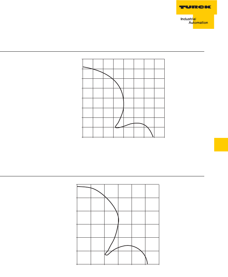
8 – 27
Overtravel ranges
D101583 0207 BL ident
8
Read-write head TN-Q80-H1147 overtravel distance with data carrier TW-R30-B128
Read-write head TN-Q80-H1147 overtravel distance with data carrier TW-R50-B128
Figure 45
Overtravel
distance TN-Q80-
H1147 with TW-
R30-B128
Figure 46
Overtravel
distance TN-Q80-
H1147 with TW-
R50-B128
0
10
20
30
40
50
60
70
80
0 1020304050607080
mm
mm
0
20
40
60
80
100
120
0 20406080100120
mm
mm
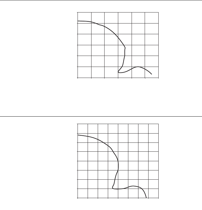
Overtravel ranges
8 – 28 D101583 0207 BL ident
Read-write head TN-Q80-H1147 overtravel distance with data carrier TW-R20-K2
Read-write head TN-Q80-H1147 overtravel distance with data carrier TW-R30-K2
Figure 47
Overtravel
distance TN-Q80-
H1147 with TW-
R20-K2
Figure 48
Overtravel
distance TN-Q80-
H1147 with TW-
R30-K2
0
10
20
30
40
50
60
0 102030405060
mm
mm
0
10
20
30
40
50
60
70
80
0 1020304050607080
mm
mm
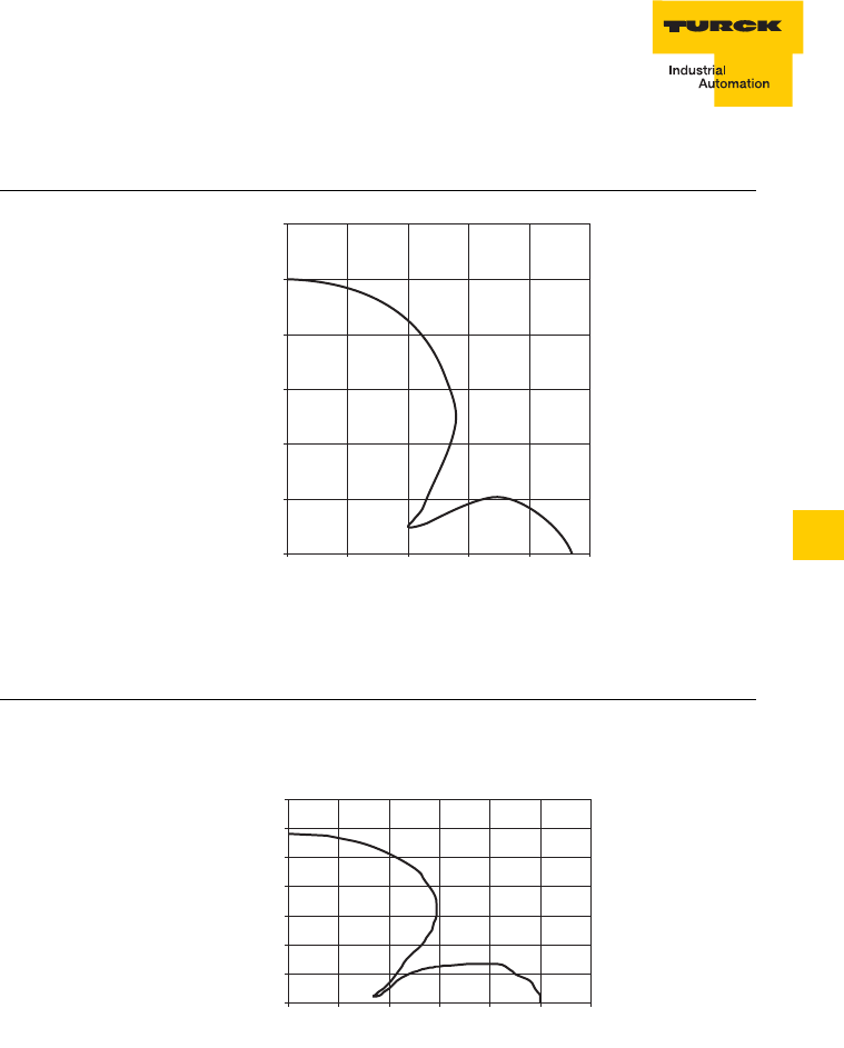
8 – 29
Overtravel ranges
D101583 0207 BL ident
8
Read-write head TN-Q80-H1147 overtravel distance with data carrier TW-R50-K2
Re
ad-write head TN-Q80-H1147 overtravel distance with data carrier TW-L43-43-F-B128
Figure 49
Overtravel
distance TN-Q80-
H1147 with TW-
R50-K2
Figure 50
Overtravel dis-
tance TN-Q80-
H1147 with TW-
L43-43-B128
0
20
40
60
80
100
120
0 20406080100
mm
mm
mm
mm
0
20
40
60
80
100
120
140
020 40 60 80 100 120
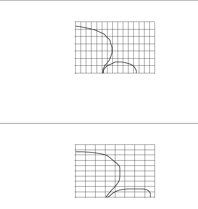
Overtravel ranges
8 – 30 D101583 0207 BL ident
Re
ad-write head TN-Q80-H1147 overtravel distance with data carrier
TW-L82-49-P-B128
Re
ad-write head TNLR-Q80-H1147 overtravel distance with data carrier
TW-R16-B128
Figure 51
Overtravel dis-
tance TN-Q80-
H1147 with TW-
L82-49-P-B128
Figure 52
Overtravel dis-
tance TNLR-Q80-
H1147 with TW-
R16-B128
mm
mm
0
20
40
60
80
100
120
140
50 100 150
mm
mm
0
10
20
30
40
50
60
70
80
90
100
020 40 60 80
10 30 50 70
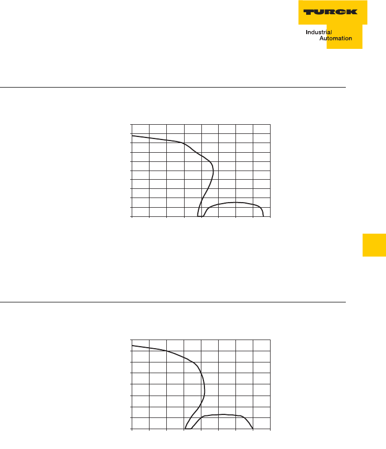
8 – 31
Overtravel ranges
D101583 0207 BL ident
8
Re
ad-write head TNLR-Q80-H1147 overtravel distance with data carrier
TW-R20-B128
Re
ad-write head TNLR-Q80-H1147 overtravel distance with data carrier
TW-R20-K2
Figure 53
Overtravel dis-
tance TNLR-Q80-
H1147 with TW-
R20-B128
Figure 54
Overtravel dis-
tance TNLR-Q80-
H1147 with TW-
R20-K2
mm
mm
0
10
20
30
40
50
60
70
80
90
100
0 20406080
10 30 50 70
mm
mm
0
10
20
30
40
50
60
70
80
0
20 40 60 80
10 30 50 70
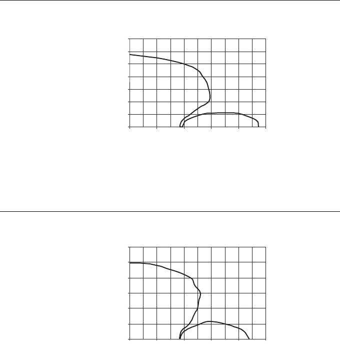
Overtravel ranges
8 – 32 D101583 0207 BL ident
Re
ad-write head TNLR-Q80-H1147 overtravel distance with data carrier
TW-R30-B128
Re
ad-write head TNLR-Q80-H1147 overtravel distance with data carrier
TW-R30-K2
Figure 55
Overtravel dis-
tance TNLR-Q80-
H1147 with TW-
R30-B128
Figure 56
Overtravel dis-
tance TNLR-Q80-
H1147 with TW-
R30-K2
mm
mm
0
20
40
60
80
100
120
140
020 40 60 80 100
0
0
mm
mm
20
40
60
80
100
120
20 40 60 80 100

8 – 33
Overtravel ranges
D101583 0207 BL ident
8
Re
ad-write head TNLR-Q80-H1147 overtravel distance with data carrier
TW-R50-B128
Re
ad-write head TNLR-Q80-H1147 overtravel distance with data carrier
TW-R50-K2
Figure 57
Overtravel dis-
tance TNLR-Q80-
H1147 with TW-
R50-B128
Figure 58
Overtravel dis-
tance TNLR-Q80-
H1147 with TW-
R50-K2
mm
mm
0
20
40
60
80
100
120
140
160
180
0 50 100 150
mm
mm
0
20
40
60
80
100
120
140
160
0 50 100 150
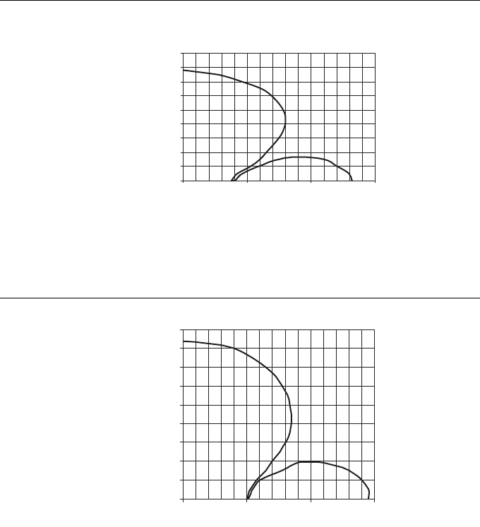
Overtravel ranges
8 – 34 D101583 0207 BL ident
Read-write head TNLR-Q80-H1147 overtravel distance with data carrier TW-L43-43-F-B128
Read-write head TNLR-Q80-H1147 overtravel distance with data carrier
TW-L82-49-P-B128
Figure 59
Overtravel dis-
tance TNLR-Q80-
H1147 with TW-
L43-43-F-B128
Figure 60
Overtravel dis-
tance TNLR-Q80-
H1147 with TW-
L82-49-P-B128
mm
mm
0
20
40
60
80
100
120
140
160
180
050 100 150
0
0
mm
mm
20
40
60
80
100
120
140
160
180
50 100 150
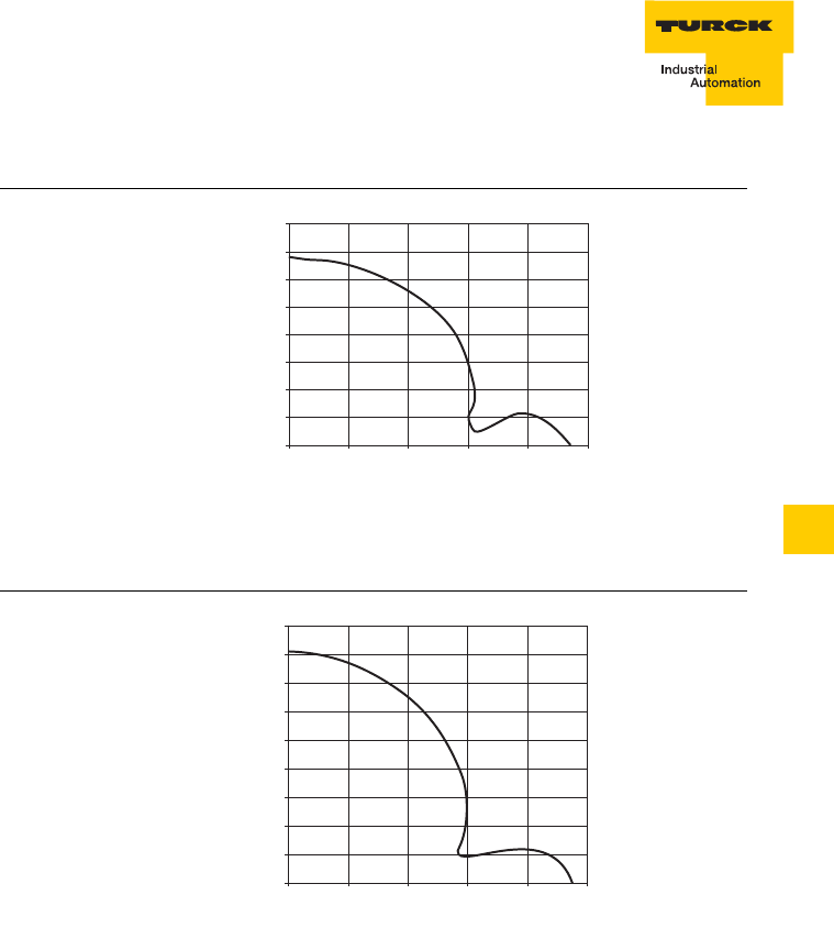
8 – 35
Overtravel ranges
D101583 0207 BL ident
8
Read-write head TN-S32XL-H1147 overtravel distance with data carrier TW-R16-B128
Read-write head TN-S32XL-H1147 overtravel distance with data carrier TW-R30-B128
Figure 61
Overtravel
distance TN-
S32XL-H1147
with TW-R16-
B128
Figure 62
Overtravel
distance TN-
32XL-H1147 with
TW-R30-B128
0
10
20
30
40
50
60
70
80
0 20406080100
mm
mm
0
10
20
30
40
50
60
70
80
90
0 20 40 60 80 100
mm
mm
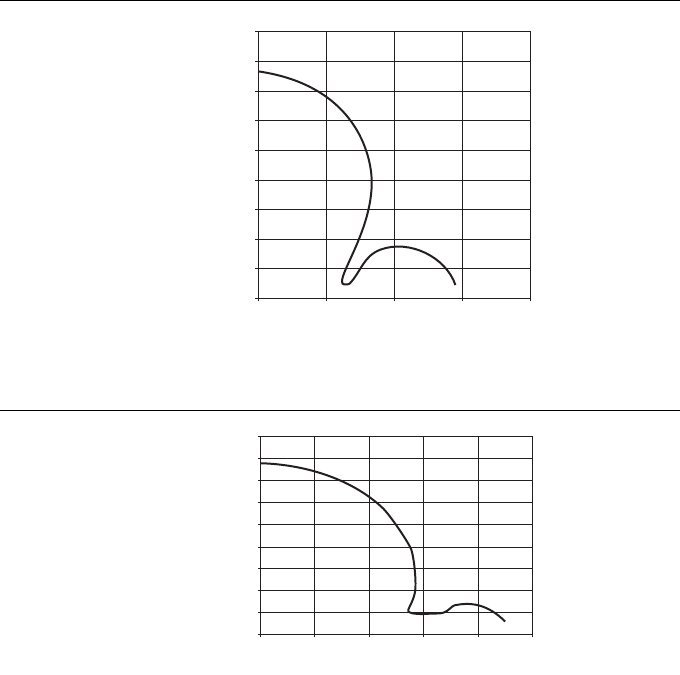
Overtravel ranges
8 – 36 D101583 0207 BL ident
Read-write head TN-S32XL-H1147 overtravel distance with data carrier TW-R50-B128.
Read-write head TN-S32XL-H1147 overtravel distance with data carrier TW-R30-K2
Figure 63
Overtravel
distance TN-
S32XL-H1147
with TW-R50-
B128
Figure 64
Overtravel
distance TN-
S32XL-H1147
with TW-R30-K2
0
20
40
60
80
100
120
140
160
180
0 50 100 150 200mm
mm
0
10
20
30
40
50
60
70
80
90
020406080100
mm
mm
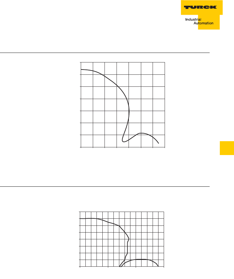
8 – 37
Overtravel ranges
D101583 0207 BL ident
8
Read-write head TN-S32XL-H1147 overtravel distance with data carrier TW-R50-K2
Read-write head TN-S32XL-H1147 overtravel distance with data carrier TW-L43-43-F-B128
Figure 65
Overtravel
distance TN-
S32XL-H1147
with TW-R50-
…K2
Figure 66
Overtravel dis-
tance TN-S32XL-
H1147 with TW-
L43-43-F-B128
0
20
40
60
80
100
120
140
0 20 40 60 80 100 120 140
mm
mm
mm
mm
0
20
40
60
80
100
120
140
160
0 50 100 150

Overtravel ranges
8 – 38 D101583 0207 BL ident
Read-write head TN-S32XL-H1147 overtravel distance with data carrier
TW-L82-49-P-B128
Figure 67
Overtravel dis-
tance TN-S32XL-
H1147 with TW-
L82-49-P-B128
mm
mm
0
20
40
60
80
100
120
140
160
180
0 50 100 150

9 – 1
Accessories
D101583 0207 BL ident
9
9 Accessories
General description of the accessories.............................................................2
Accessories for Ø 30 mm and Ø 50 mm data carriers
Spacer DS-R30 ...........................................................................................3
Spacer DS-R50 ...........................................................................................4
Accessories for cylindrical read-write heads of housing style M18
Mounting clip BS18.....................................................................................5
Mounting clip BSN18 ..................................................................................6
Mounting clip with limit stop BST-18B........................................................7
Mounting clip without limit stop BST-18N ..................................................8
Quick mounting mounts QM-18..................................................................9
Cover cap SKN/M18 .................................................................................10
Accessories for cylindrical read-write heads of housing style M30
Mounting clip with limit stop BST-30B......................................................11
Mounting clip without limit stop BST-30N ................................................12
Quick mounting mounts QM-30................................................................13
Cover cap SKN/M30 .................................................................................14
Common accessories for cylindrical read-write heads of housing style M18 and
M30
Mounting aid for BST mounting clips BST-UH .........................................15
Mounting aid for BST mounting clips BST-UV..........................................16
Inscription labels for BST mounting clips BST-BS....................................17
Accessories for rectangular read-write heads of housing style CK40
Protective mounting MF-CK40-1S............................................................18
Protective mounting MF-CK40-2S............................................................19
Protective mounting MF-CK40-3S............................................................20
Protective housing SG40...........................................................................21
Protective housing SG40/2, temperature resistant ...................................22
Adjustable rail JS 025/037 ........................................................................23
Cover cap T-CK40-T-FC ...........................................................................24
Cover cap T-CK40-D-FC, temperature resistant ......................................25
Handheld with accessories
PD-ident ....................................................................................................26
PD-ident-WLAN.........................................................................................27
PD-ident-PF...............................................................................................27
PD-ident-DS ..............................................................................................27
PD-ident-RB ..............................................................................................28
PD-ident-BC..............................................................................................28
PD-ident-RS ..............................................................................................28
PD-ident-CB..............................................................................................28

Accessories
9 – 2 D101583 0207 BL ident
General description of the accessories
TURCK provides an extensive range of accessories for mounting of
the data carriers and for mounting and protection of the read-write
heads.
Spacers are used for mounting the Ø 30 mm and Ø 50 mm data
carriers.
Suitable mounting clips as well as quick mounting mounts are
available for the cylindrical read-write heads M18 x 1 and M30 x 1.5.
The adjustable rail JS 025/037 simplifies the mounting and
adjustment of read-write heads for housing style CK40.
Additional protection against mechanical damage is provided by
protective mountings, which also simplify mounting of the CK40
housing style.
The computer Handheld PD-ident provides a range of features for
location independent writing and reading of all BL ident data carriers
under Windows CE and is also provided with WLAN and Bluetooth
functionality.
Note
Mounting accessories may possibly reduce the read-write distance
Appropriate tests should be undertaken before commissioning.
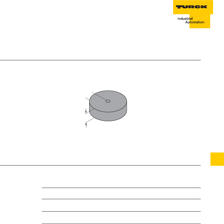
9 – 3
Accessories
D101583 0207 BL ident
9
Accessories for Ø 30 mm and Ø 50 mm data carriers
Spacer DS-R30.
Figure 1
Spacer
DS-R30
Table 1:
Spacer
DS-R30
Type DS-R30
Ident-No. 6900512
Description Spacer for data carrier Ø 30 mm
Material Plastic
10
ø 30
ø 3,9
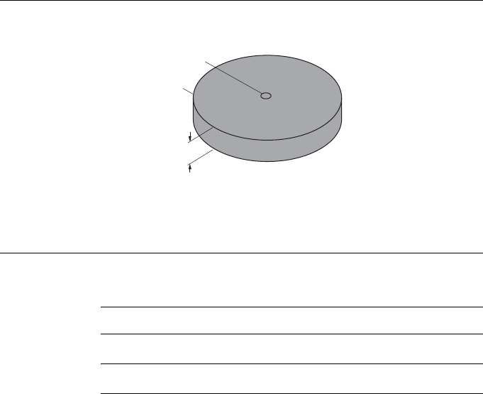
Accessories
9 – 4 D101583 0207 BL ident
Spacer DS-R50.
Figure 2
Spacer
DS-R50
Table 2:
Spacer
DS-R50
Type DS-R50
Ident-No. 6900386
Description Spacer for data carrier Ø 50 mm
Material Plastic
10
ø 50
ø 3,9
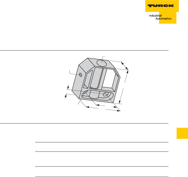
9 – 5
Accessories
D101583 0207 BL ident
9
Accessories for cylindrical read-write heads of housing style M18
Mounting clip BS185
Figure 3
Mounting clip
BS185
Table 3:
Mounting clip
BS185
Type BS18
Ident-No. 69471
Description Mounting clip for cylindrical
read-write heads M18 x 1
Material Polyamide
ø 18.2
7.5
ø 5.5
fixing
screw
40
45
22
30
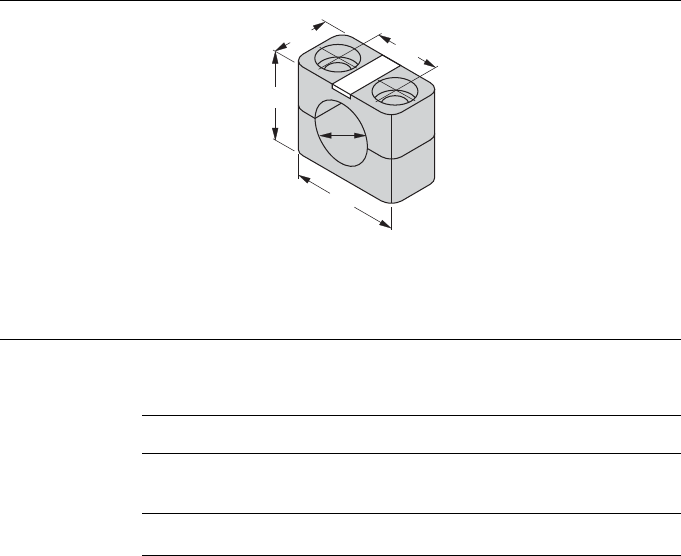
Accessories
9 – 6 D101583 0207 BL ident
Mounting clip BSN18
Figure 4
Mounting clip
BSN18
Table 4:
Mounting clip
BSN18
Type BSN18
Ident-No. 69472
Description Mounting clip for cylindrical
read-write heads M18 x 1
Material PBT
40
32
25
2
0
18
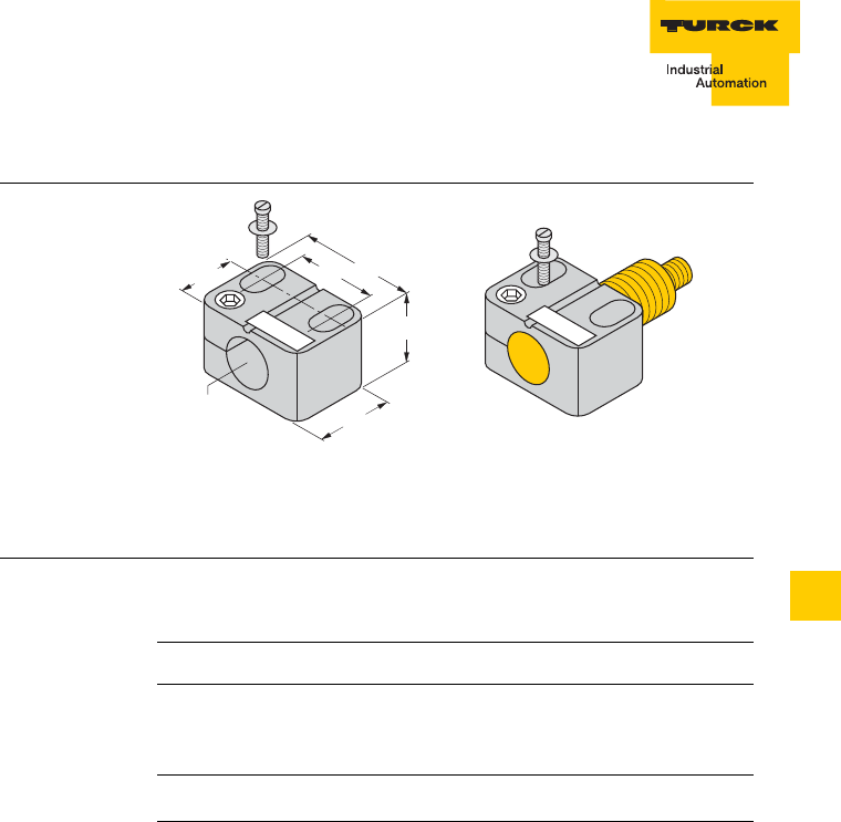
9 – 7
Accessories
D101583 0207 BL ident
9
Mounting clip with limit stop BST-18B
Figure 5
Mounting clip
BST-18B
Table 5:
Mounting clip
BST-18B
Type BST-18B
Ident-No. 6947214
Description Mounting clip with limit stop for
cylindrical read-write heads
M18 x 1
Material Polyamide
ø 18
24
30
28 40
M5
20
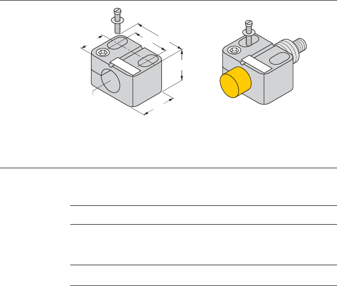
Accessories
9 – 8 D101583 0207 BL ident
Mounting clip without limit stop BST-18N
Figure 6
Mounting clip
BST-18N
Table 6:
Mounting clip
BST-18N
Type BST-18N
Ident-No. 6947215
Description Mounting clip without limit stop
for cylindrical read-write heads
M18 x 1
Material Polyamide
ø 18
24
30
28 40
M5
20
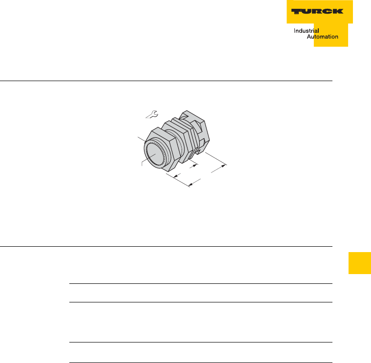
9 – 9
Accessories
D101583 0207 BL ident
9
Quick mounting mounts QM-18
Figure 7
Quick mounting
mounts QM-18
Table 7:
Quick mounting
mounts QM-18
Type QM-18
Ident-No. 6945102
Description Quick mounting mounts for
cylindrical read-write heads
M18 x 1
Material Chrome-plated brass
30/5
ø 18
36
20,5
M24 x 1,5

Accessories
9 – 10 D101583 0207 BL ident
Cover cap SKN/M18
Figure 8
Cover cap SKN/
M18
Table 8:
Cover cap SKN/
M18
Type SKN/M18
Ident-No. –
Description Teflon cover cap for cylindrical
read-write heads
M18 × 1
Material PTFE
22
M18 x 1
5
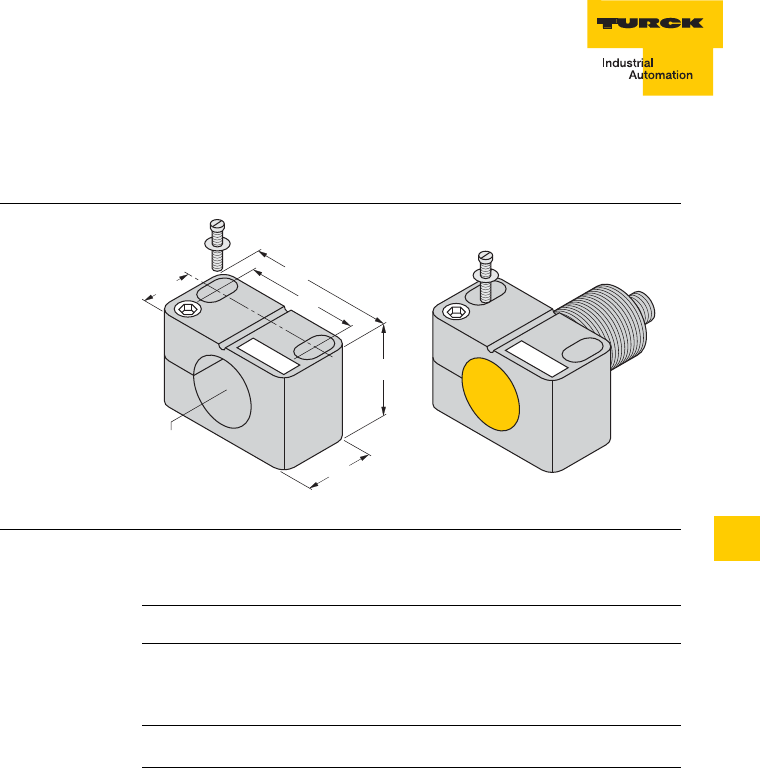
9 – 11
Accessories
D101583 0207 BL ident
9
Accessories for cylindrical read-write heads of housing style M30
Mounting clip with limit stop BST-30B
Figure 9
Mounting clip
BST-30B
Table 9:
Mounting clip
BST-30B
Type BST-30B
Ident-No. 6947216
Description Mounting clip with limit stop for
cylindrical read-write heads
M30 x 1.5
Material Polyamide
ø 30
36
30
42
54
M5
20
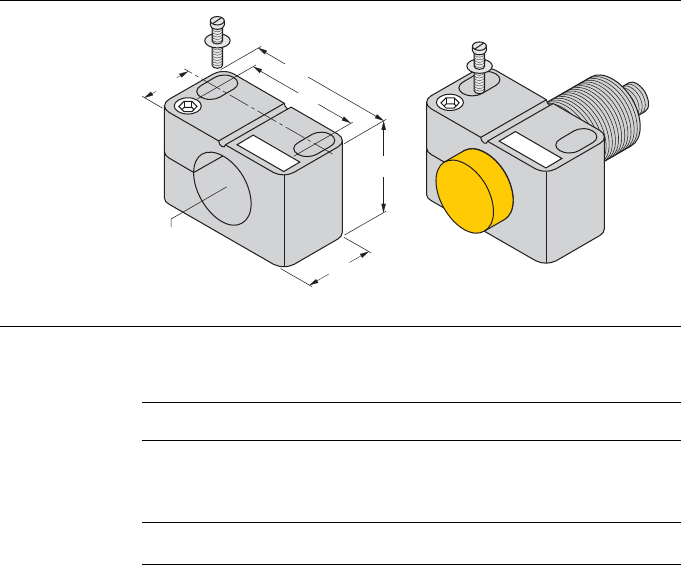
Accessories
9 – 12 D101583 0207 BL ident
Mounting clip without limit stop BST-30N
Figure 10
Mounting clip
BST-30N
Table 10:
Mounting clip
BST-30N
Type BST-30N
Ident-No. 6947217
Description Mounting clip without limit stop
for cylindrical read-write heads
M30 x 1.5
Material Polyamide
ø 30
36
30
42
54
M5
20
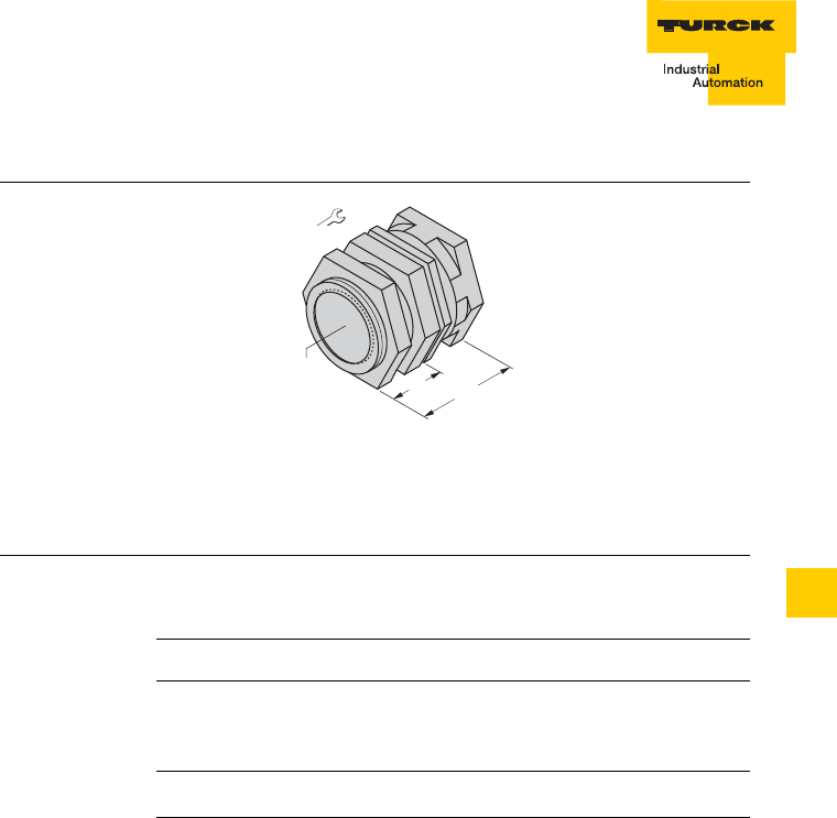
9 – 13
Accessories
D101583 0207 BL ident
9
Quick mounting mounts QM-30
Figure 11
Quick mounting
mounts QM-30
Table 11:
Quick mounting
mounts QM-30
Type QM-30
Ident-No. 6945103
Description Quick mounting mounts for
cylindrical read-write heads
M30 x 1.5
Material Chrome-plated brass
41/6
ø 30
36
20,5

Accessories
9 – 14 D101583 0207 BL ident
Cover cap SKN/M30
Figure 12
Cover cap SKN/
M30
Table 12:
Cover cap SKN/
M30
Type SKN/M30
Ident-No. –
Description Teflon cover cap for cylindrical
read-write heads
M30 × 1.5
Material PTFE
34
M30 x 1,5
9
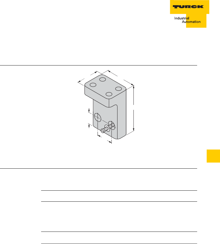
9 – 15
Accessories
D101583 0207 BL ident
9
Common accessories for cylindrical read-write heads of housing style M18 and
M30
Mounting aid for BST mounting clips BST-UH
Figure 13
Mounting aid
BST-UH
Table 13:
Mounting aid
BST-UH
Type BST-UH
Ident-No. 6947219
Description Mounting aid for BST mounting
clipsfor cylindrical read-write
heads
M18 × 1 and M30 × 1.5
Material Polyamide
60
30
24
40
15
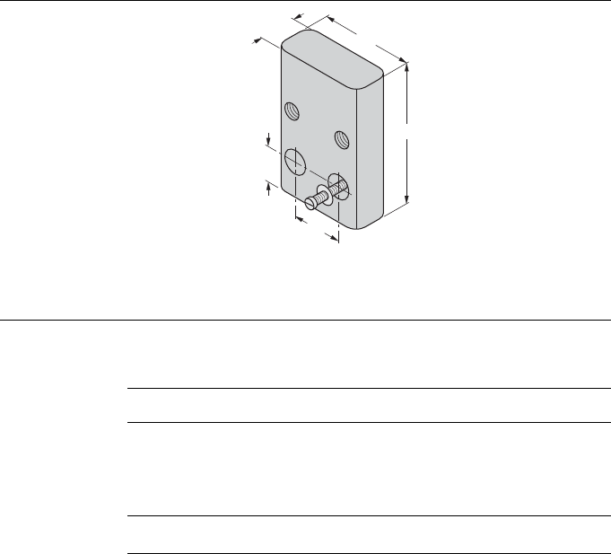
Accessories
9 – 16 D101583 0207 BL ident
Mounting aid for BST mounting clips BST-UV
Figure 14
Mounting aid
BST-UV
Table 14:
Mounting aid
BST-UV
Type BST-UV
Ident-No. 6947218
Description Mounting aid for BST mounting
clipsfor cylindrical read-write
heads
M18 × 1 and M30 × 1.5
Material Polyamide
54
13
24
40
15
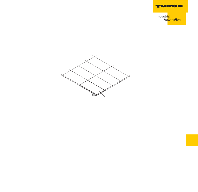
9 – 17
Accessories
D101583 0207 BL ident
9
Inscription labels for BST mounting clips BST-BS
Figure 15
Inscription labels
BST-BS
Table 15:
Inscription labels
BST-BS
Type BST-BS
Ident-No. 6947220
Description Inscription labels for BST
mounting clipsfor cylindrical
read-write heads
M18 × 1 and M30 × 1.5
Material Plastic
77x
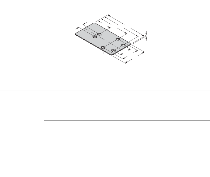
Accessories
9 – 18 D101583 0207 BL ident
Accessories for rectangular read-write heads of housing style CK40
Protective mounting MF-CK40-1S
Figure 16
Protective
mounting
MF-CK40-1S
Table 16:
Protective
mounting
MF-CK40-1S
Type MF-CK40-1S
Ident-No. 6900481
Description Protective mounting for
rectangular read-write heads of
housing style CK40 “single
sided”
Material Stainless steel, rust-free
40
30
20
22 4660 65
9
1
ø 5,3 (6x)
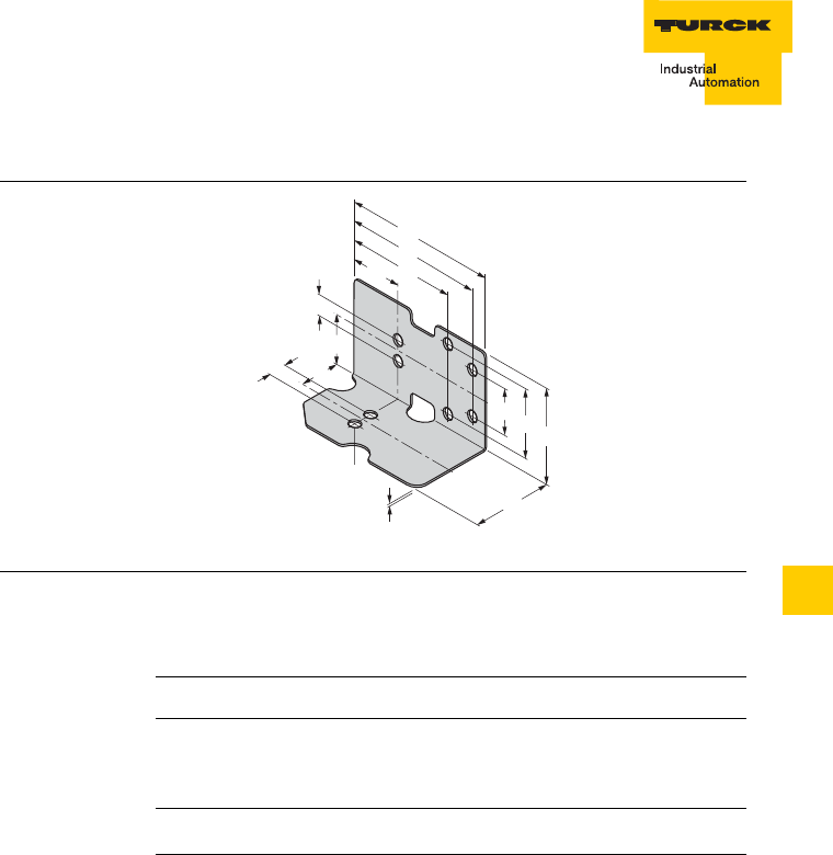
9 – 19
Accessories
D101583 0207 BL ident
9
Protective mounting MF-CK40-2S
Figure 17
Protective
mounting
MF-CK40-2S
Table 17:
Protective
mounting
MF-CK40-2S
Type MF-CK40-2S
Ident-No. 6900482
Description Protective mounting for
rectangular read-write heads of
housing style CK40 “angled”
Material Stainless steel, rust-free
60
65
43
30
9
9
21,5
20
22 46
20
40
1
ø 5,3 (8x)
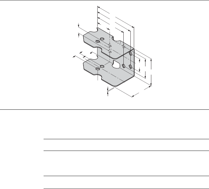
Accessories
9 – 20 D101583 0207 BL ident
Protective mounting MF-CK40-3S
Figure 18
Protective
mounting
MF-CK40-3S
Table 18:
Protective
mounting
MF-CK40-3S
Type MF-CK40-3S
Ident-No. 6900483
Description Protective mounting for
rectangular read-write heads of
housing style CK40 “U-shaped”
Material Stainless steel, rust-free
60
65
45
30
9
9
20
22 46
20
40
1
ø 5,3 (10x)
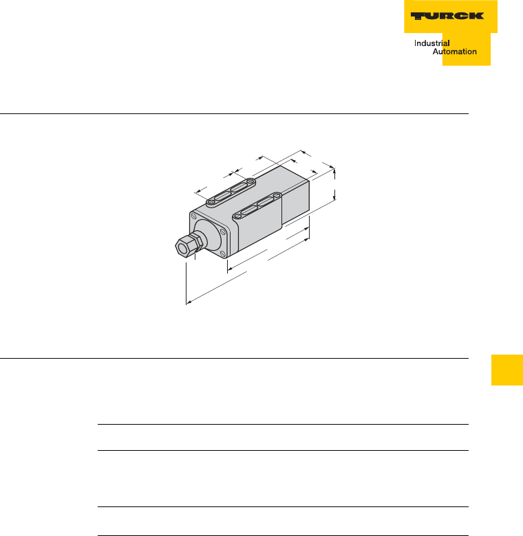
9 – 21
Accessories
D101583 0207 BL ident
9
Protective housing SG40
Figure 19
Protective
housing SG40
Table 19:
Protective
housing
SG40
Type SG40
Ident-No. 69500
Description Protective housing for
rectangular read-write heads of
housing style CK40
Material Polyamide
143
55
50
67
190
75
50
Pg 13,5
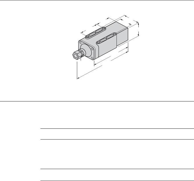
Accessories
9 – 22 D101583 0207 BL ident
Protective housing SG40/2
Figure 20
Protective
housing SG40/2
Table 20:
Protective
housing
SG40/2
Type SG40/2
Ident-No. 69497
Description Temperature-resistant
protective housing for
rectangular read-write heads of
housing style CK40
Material Ultem
143
55
50
67
190
75
50
Pg 13,5
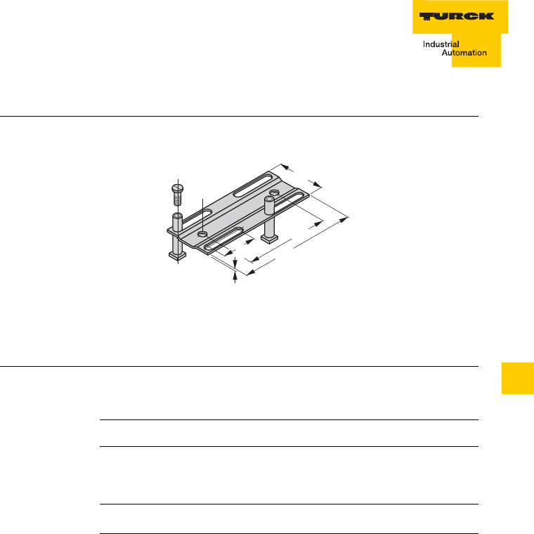
9 – 23
Accessories
D101583 0207 BL ident
9
Adjustable rail JS 025/037
Figure 21
Adjustable rail
JS 025/037
Table 21:
Adjustable rail
JS 025/037
Type JS 025/037
Ident-No. 69429
Description Adjustable rail for rectangular
read-write heads of housing
style CK40
Material Stainless steel, rust-free
30
40
ø 5,3
5
100
70

Accessories
9 – 24 D101583 0207 BL ident
Cover cap MF-CK40-1S
Figure 22
Cover cap
T-CK40-T-FC
Table 22:
Cover cap
T-CK40-T-FC
Type T-CK40-T-FC
Ident-No. 6900146
Description Teflon cover cap for rectangular
read-write heads of housing
style CK40
Material PTFE
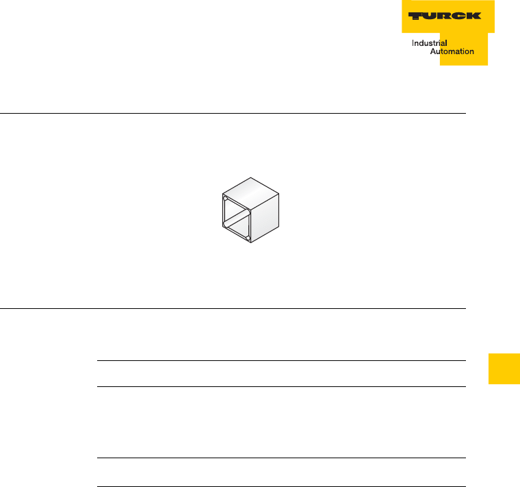
9 – 25
Accessories
D101583 0207 BL ident
9
Cover cap T-CK40-D-FC
Figure 23
Cover cap
T-CK40-D-FC
Table 23:
Cover cap
T-CK40-D-FC
Type T-CK40-D-FC
Ident-No. 6900146
Description Teflon cover cap for rectangular
read-write heads of housing
style CK40, high-temperature
resistant
Material Delrin
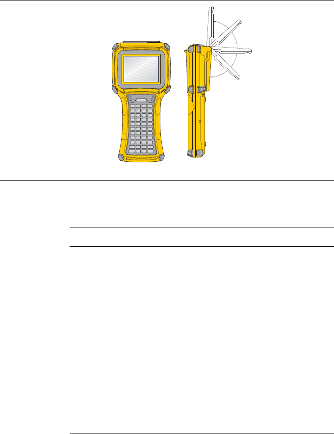
Accessories
9 – 26 D101583 0207 BL ident
Handheld with accessories
Handheld computer PD-ident
Figure 24
Handheld
computer PD-
ident
Table 24:
Handheld
computer PD-
ident
Type PD-ident
Ident-No. 1542331
Description Location-independent reading
and writing of all TURCK data
carriers
Windows CE
Lit touch screen
Protection degree IP54, opt. IP65
Programming device (handheld)
Display in decimal, binary,
hexadecimal and ASCII code
Definition of password protected
areas possible
Automatic reading of data carriers
incl. docking station

9 – 27
Accessories
D101583 0207 BL ident
9
Handheld computer PS-ident-WLAN with WLAN functionality
Handheld accessories
Table 25:
Handheld
computer PD-
ident-WLAN
Type PD-ident-WLAN
Ident-No. 1542340
Description Same features as PD-ident
additionally with WLAN and
Bluetooth functionality
Table 26:
Handheld
computer PD-
ident-PF
Type PD-ident-PF
Ident-No. 1542336
Description Display protective file (25 pieces)
Table 27:
Handheld
computer PD-
ident-DS
Type PD-ident-DS
Ident-No. 1542333
Description Docking station, incl. power
supply, RS232 cable

Accessories
9 – 28 D101583 0207 BL ident
Table 28:
Handheld
computer PD-
ident-RB
Type PD-ident-RB
Ident-No. 1542337
Description Spare rechargeable battery
Table 29:
Handheld
computer PD-
ident-BC
Type PD-ident-BC
Ident-No. 1542335
Description Rechargeable battery charger
Table 30:
Handheld
computer PD-
ident-RS
Type PD-ident-RS
Ident-No. 1542338
Description Spare pins (25 pieces)
Table 31:
Handheld
computer PD-
ident-CB
Type PD-ident-CB
Ident-No. 1542334
Description Pouch holder
D101583 0207
BL ident
9 – 29

www.turck.com
*D101583ßß0207*
D101583 0207
Irrtümer und Änderungen vorbehalten
TURCK WORLD-WIDE HEADQUARTERS
GERMANY
Hans Turck GmbH & Co. KG
Witzlebenstraße 7
45472 Mülheim an der Ruhr
P. O. Box 45466 Mülheim an der Ruhr
Phone +49 208 4952-0
Fax +49 208 4952-2 64
E-Mail more@turck.com